EP0344989B1 - Funkfernsprechapparat - Google Patents
Funkfernsprechapparat Download PDFInfo
- Publication number
- EP0344989B1 EP0344989B1 EP89305373A EP89305373A EP0344989B1 EP 0344989 B1 EP0344989 B1 EP 0344989B1 EP 89305373 A EP89305373 A EP 89305373A EP 89305373 A EP89305373 A EP 89305373A EP 0344989 B1 EP0344989 B1 EP 0344989B1
- Authority
- EP
- European Patent Office
- Prior art keywords
- identification number
- system identification
- stored
- mobile unit
- transmitting
- Prior art date
- Legal status (The legal status is an assumption and is not a legal conclusion. Google has not performed a legal analysis and makes no representation as to the accuracy of the status listed.)
- Expired - Lifetime
Links
Images


Classifications
-
- H—ELECTRICITY
- H04—ELECTRIC COMMUNICATION TECHNIQUE
- H04B—TRANSMISSION
- H04B7/00—Radio transmission systems, i.e. using radiation field
- H04B7/24—Radio transmission systems, i.e. using radiation field for communication between two or more posts
- H04B7/26—Radio transmission systems, i.e. using radiation field for communication between two or more posts at least one of which is mobile
-
- H—ELECTRICITY
- H04—ELECTRIC COMMUNICATION TECHNIQUE
- H04W—WIRELESS COMMUNICATION NETWORKS
- H04W8/00—Network data management
- H04W8/02—Processing of mobility data, e.g. registration information at HLR [Home Location Register] or VLR [Visitor Location Register]; Transfer of mobility data, e.g. between HLR, VLR or external networks
Definitions
- the present invention relates to the field of radio telecommunication apparatus used in a radio telecommunication system and, more specifically, to radio telecommunication apparatus having a plurality of identification numbers, each of which is registered in each of a plurality of areas.
- a geographical area is covered and served by breaking the area into a plurality of small zones or cells.
- a large land area can be covered by a plurality of connected cells areas.
- a mobile telephone switching office (MTSO) is provided for each area and is connected to a plurality of base stations, each covering a cell within the area.
- MTSO mobile telephone switching office
- FIG. 1 is a diagram illustrating a conventional cellular radio telephone system.
- the user of cellular radio telephone 101 usually travels within an area 102 and is assigned an identification (ID) number for the user's cellular radio telephone which is registered in a corresponding MTSO 103 which covers the area.
- the area is called a home area and the user is called a home area user. If the user travels out of area 102 and enters another area, the new area is called a roam area and the user is called a roamer in the new area.
- User fees for calls from the cellular radio telephone via the MTSO covering the roam area are high than there via the MTSO covering the home area.
- the ID number for the cellular radio telephone is transmitted to the MTSO covering the area where the cellular radio telephone is located and the MTSO can therefore distinguish roamers and home are users by checking whether the transmitted ID number is registered in the MTSO. Accordingly, some conventional cellular radio telephones have a plurality of ID numbers each one of which is registered to a different area, such as described in GB 2,172,775A.
- FIG. 2 is a further diagram illustrating a conventional cellular radio telephone system.
- the user of cellular radio telephone 201 registers ID #1 to MTSO 203 covering area #1 and ID #2 to MTSO 204 covering area #2, either area #1 or area #2 could become the home area for the user by using the ID number registered in the MTSO covering the area when a call is made.
- an ID number is manually selected by the user.
- the user has to select ID #1 by operating a changeover switch provided in the cellular radio telephone to reduce speech charges. Otherwise, ID #2 may be sent to MTSO 203 covering area #1 which would result in high speech charges because MTSO 203 identifies the call as being that from a roamer. Therefore, it is necessary for a user to pay attention to whether the proper ID number for the area is selected when the user makes a call. In some situations, however, a user does not exactly know which area he presently is in. Thus, the user cannot select the proper ID number.
- an ID number is automatically selected in response to a system identification number (SID) transmitted from a base station.
- SID system identification number
- Figure 3 is a diagram which illustrates the principles of the present invention applied to a cellular radio telecommunication system in which a MTSO is connected to a plurality of base stations, each covering a cell.
- the cellular radio telephone 301 comprises a memory 302 for storing a plurality of ID numbers, such as ID#1 and ID#2, which are associated with a plurality of corresponding system identification numbers, such as :SID#1 and SID#2.
- the telephone When the cellular radio telephone is located within home area #1, the telephone receives SID#1 transmitted from MTSO 303, in which ID#1 is registered, via a base station at the time of initialization, in a standby mode, or prior to a call origination. Responsive to the reception of SID#1, cellular radio telephone 301 selects the corresponding identification number ID#1 from memory 302 and transmits the selected number to MTSO 303 via a base unit. MTSO 303 receives the ID#1 and compares the ID#1 with identification numbers previously registered in MTSO 303. Since ID#1 is already registered in MTSO 303, MTSO 303 treats cellular radio telephone 301 as a homer area user traveling within a home area. Accordingly, speech charges in this case are cheaper than that in the case where cellular radio telephone 301 is treated as a roamer by transmitting ID#2.
- telephone 301 If cellular radio telephone 301 travels out of area #1 and enters area #2, telephone 301 receives SID#2 from MTSO 304, In which ID#2 is registered, via a base station at the time of initialization, in a standby state, or prior to a call origination. Responsive to the reception of SID#2, telephone 301 transmits the corresponding identification number ID#2 to MTSO 304 via a base station. Accordingly, telephone 301 entering area #2 is treated as a home area user in a home area by MTSO 304. Thus, speech charges are cheaper than in the case where the user is treated as a roamer. Accordingly, it is not necessary for a user of the cellular radio telephone to operate 19 of changeover switch.
- a caller may call a cellular radio telephone by dialing any one of a plurality of identification numbers registered in the cellular radio telephone.
- FIG 4 is a block diagram showing an arrangement of a mobile telephone apparatus according to an embodiment of the present invention.
- mobile telephone apparatus 100 comprises antenna 200, radio unit 300 and telephone unit 400.
- Antenna 200 is mounted on an outer body surface of an automobile.
- Telephone unit 400 is mounted near the driver's seat inside the automobile.
- Radio unit 300 includes radio section 310 for establishing radio channels 600 with a base station (not shown) through antenna 200 and for exchanging signals therewith, radio unit controller 330 for controlling the overall operations of the apparatus, voice synthesis circuit 350 for synthesizing voices, ID ROM 370 for storing ID numbers with the corresponding system identification numbers and power source 390 for supplying power from the battery mounted in the automobile to the above components through fuse 508.
- Telephone unit 400 includes handset controller 418 for controlling the overall operations of telephone unit 400 in response to instructions or the like from radio unit controller 330, key unit 430 for entering key inputs, display unit 450 for displaying numerical or alphabetical characters in response to control signals from handset controller 418, switches 470 including a hook switch and a power switch, and selectable audio input/output units 490a and 490b for inputting or outputting an audible sound.
- Telephone unit 400 may be divided into main unit 400a and handset 400b.
- Microphone 494 may be a hands-free microphone 494 mounted on a sun visor or the like near the driver's seat and is connected to main unit 400a. Loudspeaker 492 may be mounted in main unit 400a.
- Handset controller 418, key unit 430, and display unit 450 are mounted in handset 400b.
- Handset microphone 466 and handset receiver 498 constitute audio input/output unit 490b of handset 400b.
- Each section of radio unit 300, main unit 400a and handset 400b is supplied power by way of a power line 1005 extending from power source 390 in radio unit 300.
- the opened or closed status of switches 470 is transmitted to power source 390 or radio unit controller 330 by way of line 1000 or line 1001, respectively.
- Control and/or command signals are transmitted between handset controller 418 and radio unit controller 330 by way of line 1002.
- Audio signals are transmitted by way of lines 1003.
- Radio unit controller 330 sends control signals to audio input/output unit 490a, 490b by way of lines 1004.
- FIG. 5 is a block diagram showing a detailed arrangement of the radio unit of Figure 4.
- radio section 310 comprises demodulator 312, modulator 314 and synthesizer 320.
- Demodulator 312 demodulates a radio signal received from the base station through radio channels 600, antenna 200 and duplexer 318. It should be noted that this signal includes audible sound signals and control signals.
- Modulator 314 modulates the audio and control signals received from audio controller 300 and generates the required transmission signals.
- Power amplifier 316 amplifies the transmission signals received from modulator 314.
- the amplification of power amplifier 316 may be continuous or variable in a step-wise fashion, e.g., 8-step variable.
- Duplexer 318 sends the signals received through radio channel 600 to demodulator 312 and the signals from modulator 314 and power amplifier 316 to antenna 200.
- Synthesizer 320 is formed of a channel selection local oscillator and specifies a frequency from which signals are demodulated by demodulator 312 and a frequency to which signals are modulated by modulator 314. About 666 channels are available from synthesizer 320.
- Radio unit controller 330 is formed at central processing unit (CPU) 331, oscillator/frequency divider 332, address decoder 333, ROM 334, RAM 335, radio controller 336, audio circuit 337, control signal processor 338, audio circuit controller 339, digital interface 340, power controller 341 and interrupt controller 342.
- Reference numerals 343, 344 and 345 denote a data bus, an address bus and a control bus, respectively.
- CPU 331 controls the operation of radio unit controller 330.
- Oscillator/frequency divider 332 supplies clock signals to CPU 331 and divides the clock signals to supply appropriate frequency-divided pulses as timing pulses to each section of the mobile telephone apparatus requiring them.
- Address decoder 333 outputs predetermined operation signals to the components in response to instruction signals from CPU 331.
- ROM 334 stores various programs required for operation of CPU 331.
- RAM 335 stores various types of data during processing for use by CPU 331.
- Radio controller 336 controls radio section 310 in response to instructions from CPU 331. For example, radio controller 336 sends signals indicative of available frequencies to synthesizer 320, signals indicative of an amplification level to power amplifier 316, and signals indicative of modulation parameters to modulator 314.
- Radio controller 336 receives a step-out signal from synthesizer 320 and output power detection signals from power amplifier 316 and forwards these signals to CPU 331, thereby preventing operational errors.
- Audio circuit 337 extracts control signals and audio signals from the received signals demodulated by demodulator 312 and supplies the control signals to control signal processor 338 and the audio signals to telephone unit 400. Audio circuit 337 also supplies a control signal from control signal processor 338 and audio signals from telephone set 400 to modulator 314. It should be noted that audio circuit 337 also arranges the waveform of the control signal to be sent to control signal processor 338 in a particular signal format and filters the control signal to be supplied to modulator 314. Control signal processor 338 acquires bit and frame synchronization with the control signal from audio circuit 337.
- control signal processor 338 converts the serial control signals, including control data received from a base station, into parallel signals and converts the parallel control data signals to be transmitted to a base station into serial signals.
- the control signals are sent to and from the base station via audio circuit 337.
- Audio circuit controller 339 controls audio circuit 337. Under the control of audio circuit controller 339, for example, audio circuit 337 applies the received signals from demodulator 312 to control signal processor 338 or telephone unit 400 and selectively receives the signals from control signal processor 338 or telephone unit 400. Digital interface 340 interfaces the data communication between radio unit 300 and telephone unit 400. Power controller 341 controls power source 390 and sets a voltage supplied from battery 506 to power source 390 to a predetermined level. The voltage having the predetermined level is supplied to the respective circuit components.
- FIG. 6 is a diagram which illustrates the contents of ID ROM 370 shown in Figures 4 and 5.
- three mobile identification numbers MID1-3 which are identification numbers for the mobile telephone, are stored with corresponding system identification numbers :SID1-3 at predetermined addresses in ID ROM 370, i.e., FF00-FF20.
- a user has to register mobile identification number MID1 to a MTSO whose system identification number is SID1 as a home area user.
- MID2 and MID3 have to be registered to MTSOs having SID2 and SID3, respectively.
- FIG 8 is a detailed flow chart which illustrates the initial radio channel connection operation after the power supply is turned on.
- radio controller 336 in radio unit controller 330 controls synthesizer 320 to change the frequency of output therefrom.
- a predetermined range of control channels (referred to as D channels hereinafter) are scanned in demodulator 312 to obtain the information indicative of electric field intensity of the received signals over each channel (step 1301).
- the channel having the strongest electric field intensity is selected from the D channels and the apparatus is ready for receiving signals through the D channel having the strongest electric field intensity. In this case, information of a channel having the second strongest intensity is also obtained.
- audio circuit controller 339 controls audio circuit 337 so that the output of demodulator 312 is applied to the input of control signal processor 338 and the output of control signal processor 338 is applied to the input of modulator 314.
- Control signal processor 338 performs bit and frame synchronization operations on signals received through the selected D channel (step 1302). Thereby, a communication link is established between the mobile telephone and a base station. System information is then detected by signals received through this D channel at control signal processor 338 (step 1303) and sent to CPU 331.
- the system information includes a system identification number (SID) and a range of frequency channels (referred to as P channels hereinafter) to be scanned next.
- SID system identification number
- P channels a range of frequency channels
- CPU 331 selects a MID corresponding to the coincided SID.
- CPU 331 selects a MID having a predetermined priority.
- the selected MID is stored in a MID register of RAM 335 as an identification number for the mobile telephone (step 1305).
- the demodulator scans the D channels again (step 1301).
- FIG. 9 is a detailed flow chart which illustrates the P channel connection after initialization.
- radio controller 336 controls synthesizer 320 to change the frequency of the output therefrom so that P channels are scanned in demodulator 312 (step 1401) to obtain the information indicative of the electric field intensity of the received signals.
- the apparatus is ready for receiving Information through the P channel having the strongest electric field intensity. In this case, information indicative of the P channel having the second strongest intensity is also obtained.
- Control signal processor 338 performs bit and frame synchronization operations on signals received through the P channel which has the strongest electric field intensity (step 1402). After acquiring synchronization, control signal processor 38 obtains system information, including a SID representing a MTSO serving for the mobile telephone, from the following information signals (step 1403) and sends it to CPU 331.
- system information including a SID representing a MTSO serving for the mobile telephone
- CPU 331 compares the obtained SID with SIDs stored in ID ROM 370 ( Figures 4 and 6). Referring to Figure 6, in the event that the obtained SID coincides with one of the stored SIDS (SID1, SID2 or SID3) CPU 331 selects a MID corresponding to the coincided SID. In the event that the obtained SID does not coincide with any one of the stored SIDS, CPU 331 selects a MID having a predetermined priority. The selected MID is stored In a MID register of RAM 335 ( Figure 5) as an identification number of the mobile telephone (step 1405).
- step 1404 If the word synchronization or system information reception is not performed within a predetermined period of time, an operation similar to the one described above is performed for the P channel having the second strongest intensity (step 1404). In this case, when word synchronization or system information reception is again not performed within the predetermined period of time, initialization is resumed (step 1102). If position information is not obtained from system information, initialization is also resumed (step 1102). The above connection control operations set the apparatus to the receive standby mode (step 804).
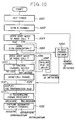
- Figure 10 is a detailed flow chart showing outgoing call processing.
- a timer for counting a call reception time is set (step 1201).
- the set time is, e.g., 12 seconds.
- the audio controller in the radio unit causes the demodulator to scan each predetermined control channel (step 1202) to obtain reception electric field intensity information.
- the channel having the strongest electric field intensity is selected from these control channels and the apparatus is set to receive a signals through the control channel having the strongest intensity. In this case, information indicative of the control channel having the second strongest electric field intensity is also obtained.
- step 1203 the presence of the user wishing to make a call is checked. This check is performed as follows. If the user enters a telephone number to be called on key pad 430 and depresses the "SEND" key, these key inputs are detected by handset controller 418. Handset controller 418 sends a detection signal to CPU 331 in radio unit controller 330. Responsive to the detection signal, a call flag in CPU 331 is set at a logic "1." In this case, the apparatus determines that the user wishes to make a call.
- the apparatus determines that the user does not wish to make a call and initialization is resumed (step 802).
- Control signal processor 338 performs bit and frame synchronization operations of the currently received control channel. That is, word synchronization thereof to obtain system information from this control channel.
- CPU 331 then obtains a SID from the received system information and compares the obtained SID with SIDs stored in ID ROM 370 ( Figures 4 and 6). Referring to Figure 6, in the event that the obtained SID coincides with one of the stored SIDs, CPU 331 selects a MID corresponding to the coincided SID. In the event that the obtained SID coincides with neither one of the stored SIDs, CPU 331 selects a MID having priority which is predetermined. The selected MID is stored in the MID register of RAM 335 ( Figure 5) as an identification number of the mobile telephone (step 1204). However, if word synchronization cannot be performed, the same operation is performed using the control channel having the second strongest intensity (step 1205). In this case, if no word synchronization can be performed, initialization is resumed (step 802).
- the apparatus confirms again whether the user wishes to make a call (step 1206). As described above, if the call flag is set at logic "1," the apparatus determines that the user wishes to make a call. However, if the call flag is set at logic "0," the apparatus determines that the user does not wish to make a call and initialization is resumed (step 802).
- CPU 331 confirms whether the selected control channel is appropriate for the origination signal to be broadcast by analyzing the system information signal from a base station. Upon the selection of an appropriate control channel, a channel selection flag in CPU 331 is changed from logic "0" to "1.” However, if any appropriate control channel is not selected, initialization is resumed (step 802) without changing the content of the channel selection flag. If the selection of an appropriate control channel is delayed (step 1208), the apparatus checks again whether the user wishes to make a call. (step 1206).
- CPU 331 detects that the user wishes to make a call (i.e., the call flag is set at logic "1") and an appropriate control channel for broadcast of an origination signal is selected (i.e., the channel selection flag is set at logic "1"), a call origination signal including the telephone number to be called, which is entered by the user, is transmitted over this control channel with a MID (step 1209).
- the MID to be transmitted is stored in the MID register of RAM 335 ( Figure 5) in step 1305 of Figure 8, step 1405 of Figure 9 or step 1204. Accordingly, as a MID corresponding to a SID assigned to the serving MTSO is stored in the MID register of RAM 335, if any, the mobile telephone may be treated as a homer by the MTSO.
- CPU 331 sends the MID to handset controller 418 of transceiver unit 400b via digital interface 340. Receiving the MID, handset controller 418 controls display unit 450 so that the MID is displayed (step 1210). Also, CPU 331 may control voice synthesizer 350 so that sounds corresponding to the MID are synthesized and control audio circuit 337 so that the synthesized sounds are generated from loudspeaker 492.
- the mobile telephone apparatus detects whether the acknowledge signal from the base station has been received (step 1211).
- the base station calls the other party to be called on the basis of the telephone number included in the origination signal.
- a communication link may then be established between the mobile telephone apparatus and the called telephone apparatus (step 1212). Otherwise, initialization is resumed (step 802).
- a communication link can be established as mentioned above (step 810), and thereafter the communication is closed.
- an MID corresponding to an SID of the MTSO serving the mobile telephone is transmitted to a base station. Accordingly, since the MTSO treats the mobile telephone as a home area user, it reduces speech charges for the mobile telephone.
- a location registration procedure In the present cellular radio telephone system, in addition to a call origination procedure, a location registration procedure is provided. In this procedure, to register a location where the mobile telephone exists to a base station, an MID of the mobile telephone is automatically transmitted to the base station. This procedure occurs by a request from a base station or during a processing of the mobile telephone and is not actuated by a user's operation. Before this procedure, a mobile telephone can obtain a system identification number through an initialization procedure (step 802 of Figure 7) or the other procedures. Therefore, the mobile telephone may transmit an MID corresponding to an SID of the MTSO serving the mobile telephone in the automatic location registration procedure before a call is made by a user of the apparatus.
- CPU 331 selects an MID having a predetermined priority in the event that the received SID does not coincide with any one of the stored SIDs
- an MID corresponding to an SID which is the most similar one with the received SID may be selected by comparing the received SID with the stored SIDs. For example, in the event that the received SID is "11111111", and SIDs "11111110" and "99999999" are stored, a MID corresponding to the SID "11111110" is selected.
- the SIDs are sequentially assigned to a plurality of MTSOs by a geographical order, speech charges for the mobile telephone may be reduced since the mobile telephone is treated as a roamer from a near area.
- MID register of RAM 335 may be displayed in response to a user's input for confirmation. For example, when the user depresses a predetermined order of keys on key unit 430, handset controller 418 detects this key input, reads the MID stored in the MID register of RAM 335, and controls display unit 450 so that the read MID is displayed on display unit 450. Also, upon the input for confirmation, CPU 331 may control voice synthesizer 350 so that sounds corresponding to the MID stored in the MID register of RAM 335 are synthesized and control audio circuit 337 so that the synthesized sounds are generated from loudspeaker 492.
- the apparatus awaits an incoming call. Signals received over a selected P channel are applied to CPU 331 through audio circuit 337 and control signal processor 338. CPU 331 then examines whether the signals comprise one of the MID1-MID3 registered in ID ROM 370. Upon a match of an MID, a speech communication link is established by using the matched ID thereafter until the speech communication link is terminated. Then, an acknowledge signal is sent back through a predetermined channel. At the same time, scanning of control channels (referred to as A channels hereinaftar) for receiving control signals from the base station is performed in the same manner as for D and P channels. A frequency range of A channels is designated in the system information addressed to the apparatus which is obtained from signals transmitted via the P channel.
- a channels hereinaftar
- radio controller 336 controls synthesizer 320 to change the frequency of output therefrom so that A channels are scanned in demodulator 312 to obtain the information indicative of electric field intensity of the received signal.
- the apparatus is then ready for receiving information through the A channels having the strongest electric field intensity.
- control signal processor 338 performs bit and frame synchronization operations, i.e., word synchronization.
- This radio channel communication using A channels is also a communication link between the mobile telephone and the base station.
- the channels are switched to the designated speech channels which include a forward channel for transmitting audio signals to the base station and a backward channel for receiving audio signals from the calling apparatus via the base station (step 1107). Thereby a communication link has been established between the mobile telephone and the calling apparatus via the base station.
- handset controller 418 detects the key operation and sends a control signal of "SEND" key operation to CPU 331 via digital interface 340 by way of lines 1002. Also in the event that the user takes handset 400b off-hook, information indicating the closed state of the hook switch in switch 470 ( Figure 4) is transmitted to CPU 331 via digital interface 340 by way of line 1001. Responsive to the off-hook control signal or the information, CPU 331 sends a connection signal to audio circuit controller 339. Receiving the connection signal, audio circuit controller 339 controls audio circuit 337 so that demodulator 312 and modulator 314 are connected to audio input/output unit 490 by way of line 1003.
- the user may communicate with the calling party by using hands-free microphone 494 and loudspeaker 492 or handset microphone 466 and handset receiver 498.
- the acknowledge signal sending state, or a communication enable state the transmission function is disabled.
- the transmission function is disabled, initialization is resumed (step 1102).
- a location information of a mobile telephone is registered in a base station and renewed through the automatic location registration procedure.
- the base station usually broadcasts a paging signal, i.e., an incoming signal to a base station with the registered MID and may not broadcast a paging signal with the other MID.
- the mobile telephone in accordance with this embodiment may receive an incoming call with any MIDs that the mobile telephone has.
- this invention may be easily applied to any kind of radio telecommunication apparatus, for example, to a transportable type radio telephone or a portable type radio telephone.
- This invention also is applicable to a cordless telephone system wherein a plurality of zones are covered by a plurality of base units and a mobile unit (a cordless telephone) is capable of communicating with the apparatus wherever the mobile unit moves around within the zones.
- the concepts of the present invention may be applied to a data transmission apparatus used in a cellular radio telecommunication system.
Claims (18)
- Mobiles Funknachrichtengerät für die Verwendung in einem Funknachrichtensystem der Art, bei dem eine oder mehr Basiseinheiten innerhalb eines Bereichs eine System-Kennummer über einen oder mehrere Funkkanäle aussenden, wobei dieses Gerät umfaßt:
ein Empfangsmittel (310) für den Empfang einer System-Kennummer und
ein Speichermittel (370) für das Speichern einer Vielzahl von Mobileinheit-Kennumern für dieses Gerät, welchen jeweils eine entsprechende System-Kennummer zugeordnet ist, gekennzeichnet durch:
ein Übertragungsmittel (330), das auf das Empfangsmittel und das Speichermittel reagieren kann, um die gespeicherte Mobileinheits-Kennummer für dieses Gerät zu übertragen, welche der gespeicherten System-Kennummer zugeordnet ist, welche zu der empfangenen System-Kennummer paßt. - Gerät nach Anspruch 1, welches weiterhin ein Anruf-Abgabemittel (430) umfaßt, wodurch der Nutzer einen Anruf abgeben und die Adreßinformation eines anzurufenden Apparats eingeben kann.
- Gerät nach Anspruch 1 oder 2, wobei das Übertragungsmittel weiterhin eine Kennummer für den Apparat umfaßt, die einer der gespeicherten Kennummern entspricht, welche eine vorbestimmte Beziehung zu der empfangenen System-Kennummer für den Fall hat, daß die empfangene System-Kennummer nicht mit irgendeiner der gespeicherten System-Kennumern identisch ist.
- Gerät nach Anspruch 1 oder 2, wobei das Übertragungsmittel weiterhin eine vorbestimmte Kennummer für den Fall überträgt, daß die empfangene System-Kennummer nicht mit irgendeiner der gespeicherten Kennummern identisch ist.
- Gerät nach einem der vorhergehenden Ansprüche, welches weiterhin ein Alarmmittel für das Alarmieren des Nutzers des Geräts als Reaktion auf die Übertragung einer Kennummer des Geräts umfaßt.
- Gerät nach einem der vorhergehenden Ansprüche, welches weiterhin ein Ausgabemittel (450) für die Ausgabe der übertragenen Kennummer des Geräts als Reaktion auf die Übertragung der Kennummer des Geräts umfaßt.
- Gerät nach einem der vorhergehenden Ansprüche, welches weiterhin ein Sprachsynthesemittel für die Erzeugung eines synthetisierten Sprache entsprechend der übertragenen Kennummer des Geräts als Reaktion auf die Übertragung der Kennummer des Geräts umfaßt.
- Gerät nach Anspruch 1, welches weiterhin ein Eingabemittel für das Eingeben einer Bestätigungs-Anforderung und ein Ausgabemittel für die Ausgabe der übertragenen Kennummer des Geräts als Reaktion auf die eingegebene Bestätigungsanforderung umfaßt.
- Gerät nach einem der Ansprüche 1 bis 7, welches weiterhin ein Eingabemittel für das Eingeben einer Bestätigungsanforderung und ein Sprachsynthesemittel für das Erzeugen einer synthetisierten Sprache entsprechend der übertragenen Kennnummer des Geräts als Reaktion auf die Eingabe der Bestätigungsanforderung umfaßt.
- Gerät nach Anspruch 2, welches weiterhin ein Alarmmittel für das Alarmieren des Nutzers des Geräts als Reaktion auf die Eingabe der Anruf-Abgabeanforderung umfaßt, wenn keine der gespeicherten System-Kennummern zu der empfangenen System-Kennummer paßt.
- Gerät nach Anspruch 10, wobei das Alarmmittel ein Sprachsynthesemittel für das Synthetisieren einer vorbestimmten Sprache umfaßt.
- Mobiles Funk-Nachrichtengerät, das bei einem Funk-Nachrichtensystem verwendet wird, wobei eine oder mehrere Basiseinheiten innerhalb eines Bereichs eine System-Kennummer über einen oder mehrere Funkkanäle aussenden, welches umfaßt:
ein Empfangsmittel für das Empfangen der System-Kennummer, und
ein Speichermittel für das Speichern einer Vielzahl von System-Kennummern, wobei jede Kennummer des Geräts einer System-Kennummer zugeordnet ist, gekennzeichnet durch
ein Vergleichsmittel, das mit dem Empfangsmittel und dem Speichermittel gekoppelt ist, um die empfangene System-Kennnummer mit den gespeicherten System-Kennummern zu vergleichen;
ein Eingabemittel für die Eingabe einer Anruf-Abgabeanforderung und einer Adreßinformation des anzurufenden Geräts;
ein Übertragungsmittel, das mit dem Vergleichsmittel gekoppelt ist, um die gespeicherte Kennummer, welche den gespeicherten System-Kennummern zugeordnet sind, welche zu der empfangenen System-Kennummer passen, mit der eingegebenen Adreßinformation zur Basisstation als Reaktion auf die Anruf-Abgabeanforderung zu übertragen. - Verfahren des Registrierens des Standorts einer Mobileinheit für die Verwendung bei einem Funk-Nachrichtensystem, wobei jede Basiseinheit innerhalb eines Bereichs eine System-Kennnummer über einen oder mehrere Funkkanäle aussendet, welches die folgenden Schritte umfaßt:
Speichern einer Vielzahl von Mobileinheits-Kennummern in der mobilen Einheit, wobei jede Kennummer der mobilen Einheit einer entsprechenden System-Kennummer zugeordnet ist;
Empfangen einer System-Kennummer, die von einer Basisstation ausgesendet wird;
Vergleichen der empfangenen System-Kennummer mit den gespeicherten System-Kennummern; gekennzeichnet durch
Übertragen der gespeicherten Mobileinheits-Kennummer, welche der gespeicherten System-Kennummer entspricht, welche zu der empfangenen System-Kennummer paßt, zur Basisstation. - Verfahren nach Anspruch 13, wobei der Übertragungsschritt weiterhin den Schritt des Übertragens einer vorbestimmten Kennummer der Mobileinheit für den Fall umfaßt, daß die empfangene System-Kennummer nicht mit irgendeiner der gespeicherten System-Kennummern identisch ist.
- Verfahren nach Anspruch 13, wobei der Übertragungsschritt weiterhin den Schritt des Übertragens einer Kennummer der mobilen Einheit umfaßt, die einer der gespeicherten Kennnummern entspricht, welche der empfangenen System-Kennummer am ähnlichsten ist, wenn die empfangene System-Rennummer nicht mit irgendeiner der gespeicherten System-Kennummern identisch ist.
- Verfahren zur Abgabe eines Anrufs von einer mobilen Einheit zur Verwendung bei einem Funk-Nachrichtensystem, wobei jede Basiseinheit innerhalb eines Bereichs eine System-Kennummer über einen oder mehrere Funkkanäle aussendet, welches die folgenden Schritte umfaßt:
Speichern einer Vielzahl von Mobileinheits-Kennummern und einer Vielzahl von System-Kennumern in der mobilen Einheit, wobei jede Mobileinheits-Kennummer einer der System-Kennnummern zugeordnet ist;
Registrieren einer Anrufabgabeanforderung von dem Nutzer, die eine Adreßinformation eines anzurufenden Apparats einschließt;
Empfangen der von einer Basiseinheit ausgesendeten System-Kennummer;
Vergleichen der empfangenen System-Kennummer mit den gespeicherten System-Kennummern; gekennzeichnet durch
Übertragung der Mobileinheits-Kennummer der mobilen Einheit, welche den gespeicherten System-Kennummern zugeordnet sind, welche zu der empfangenen System-Kennummer paßt, mit der Adreßinformation zur Basiseinheit als Reaktion auf die Anrufabgabeanforderung. - Verfahren nach Anspruch 16, wobei der Übertragungsschritt weiterhin den Schritt des Übertragens einer Kennummer der mobilen Einheit umfaßt, die einer der gespeicherten System-Kennumern am ähnlichsten ist, wenn die empfangene System-Kennummer nicht mit irgendeiner der gespeicherten System-Kennummern identisch ist.
- Verfahren nach Anspruch 16, wobei der Übertragungsschritt weiterhin den Schritt des Übertragens einer vorbestimmten Kennummer der mobilen Einheit umfaßt, wenn die empfangene System-Kennummer nicht mit irgendeiner der gespeicherten System-Kennunmern identisch ist.
Applications Claiming Priority (4)
| Application Number | Priority Date | Filing Date | Title |
|---|---|---|---|
| JP63132072A JP2809641B2 (ja) | 1988-05-30 | 1988-05-30 | 移動局装置 |
| JP132072/88 | 1988-05-30 | ||
| JP63132071A JP2854579B2 (ja) | 1988-05-30 | 1988-05-30 | 移動局装置 |
| JP132071/88 | 1988-05-30 |
Publications (3)
| Publication Number | Publication Date |
|---|---|
| EP0344989A2 EP0344989A2 (de) | 1989-12-06 |
| EP0344989A3 EP0344989A3 (de) | 1991-11-06 |
| EP0344989B1 true EP0344989B1 (de) | 1994-01-19 |
Family
ID=26466724
Family Applications (1)
| Application Number | Title | Priority Date | Filing Date |
|---|---|---|---|
| EP89305373A Expired - Lifetime EP0344989B1 (de) | 1988-05-30 | 1989-05-26 | Funkfernsprechapparat |
Country Status (5)
| Country | Link |
|---|---|
| US (1) | US5101500A (de) |
| EP (1) | EP0344989B1 (de) |
| KR (1) | KR920005906B1 (de) |
| CA (1) | CA1318356C (de) |
| DE (1) | DE68912407T2 (de) |
Cited By (1)
| Publication number | Priority date | Publication date | Assignee | Title |
|---|---|---|---|---|
| EP0579655A1 (de) | 1991-04-12 | 1994-01-26 | Comvik Gsm Ab | Verfahren in mobiltelefonsystemen, in welchem einem teilnehmerkennungsmodul mindenstens zwei kennungen zugeteilt sind, die wahlweise durch den teilnehmer aktiviert werden. |
Families Citing this family (130)
| Publication number | Priority date | Publication date | Assignee | Title |
|---|---|---|---|---|
| US5303286A (en) * | 1991-03-29 | 1994-04-12 | Space Systems/Loral, Inc. | Wireless telephone/satellite roaming system |
| EP0347167A3 (de) * | 1988-06-14 | 1991-11-13 | Kabushiki Kaisha Toshiba | Funkfernsprechapparat |
| US5128981A (en) * | 1989-05-24 | 1992-07-07 | Hitachi, Ltd. | Radio communication system and a portable wireless terminal |
| JP2545466B2 (ja) * | 1989-08-24 | 1996-10-16 | 日本電信電話株式会社 | 移動通信位置登録方法 |
| US5020091A (en) * | 1989-12-26 | 1991-05-28 | Motorola Inc. | Automatic new radiotelephone system registration notification |
| JP2867538B2 (ja) * | 1990-01-30 | 1999-03-08 | 日本電気株式会社 | チャンネル選択方式 |
| JP3104878B2 (ja) * | 1990-01-31 | 2000-10-30 | 株式会社東芝 | 無線通信装置 |
| SE465198B (sv) * | 1990-02-02 | 1991-08-05 | Televerket | Foerfarande och anordning foer att utoeka kapaciteten i ett mobiltelefonsystem |
| US5687218A (en) * | 1990-02-15 | 1997-11-11 | Canon Kabushiki Kaisha | Cordless telephone |
| GB2243976B (en) * | 1990-02-20 | 1994-09-07 | Nec Corp | Location registration and paging procedure for mobile communication |
| SE465992B (sv) * | 1990-04-10 | 1991-11-25 | Ericsson Telefon Ab L M | Mobiltelefonisystem avsett att brukas av abonnenter inomhus och utomhus |
| AU636220B2 (en) * | 1990-04-17 | 1993-04-22 | Nec Corporation | Cordless key telephone system for covering multiple service areas having exclusively assigned control channels |
| US5081703A (en) * | 1990-06-27 | 1992-01-14 | Pactel Corporation | Satellite mobile communication system for rural service areas |
| US5077790A (en) * | 1990-08-03 | 1991-12-31 | Motorola, Inc. | Secure over-the-air registration of cordless telephones |
| JP2927920B2 (ja) * | 1990-09-14 | 1999-07-28 | 日本電信電話株式会社 | 位置登録制御方式 |
| JP2809872B2 (ja) * | 1990-11-29 | 1998-10-15 | 松下電器産業株式会社 | 移動体通信装置 |
| US5475689A (en) * | 1990-12-06 | 1995-12-12 | Hughes Aircraft Company | Cellular telephone with datagram and dispatch operation |
| US5734981A (en) * | 1991-01-17 | 1998-03-31 | Highwaymaster Communications, Inc. | Method and apparatus for call delivery to a mobile unit |
| US5155689A (en) * | 1991-01-17 | 1992-10-13 | By-Word Technologies, Inc. | Vehicle locating and communicating method and apparatus |
| CA2064646A1 (en) * | 1991-04-02 | 1992-10-03 | Kipling W. Fyfe | Automatic number assignment module selection for mobile telephone |
| JPH04319899A (ja) * | 1991-04-19 | 1992-11-10 | Fujitsu Ltd | 自動車電話付属回路 |
| JP2653000B2 (ja) * | 1991-04-24 | 1997-09-10 | 日本電気株式会社 | 移動無線通信方式 |
| US5463675A (en) * | 1991-06-17 | 1995-10-31 | At&T Ipm Corp. | Extended home indentification being used by the same service provider as a home identification in a service area other than the home service area for cellular radio telephone systems |
| CA2071027A1 (en) * | 1991-06-26 | 1992-12-27 | Eiji Kito | Mobile communication system wherein a base station tranfers to another an identifier for a cell of call origination |
| FI96564C (fi) * | 1991-07-08 | 1996-07-10 | Nokia Mobile Phones Ltd | Yksityispuhelinnumero solukkopuhelinjärjestelmässä |
| US5526404A (en) * | 1991-10-10 | 1996-06-11 | Space Systems/Loral, Inc. | Worldwide satellite telephone system and a network coordinating gateway for allocating satellite and terrestrial gateway resources |
| CA2078932C (en) * | 1991-10-10 | 2003-12-02 | Robert A. Wiedeman | Satellite telecommunications system using network coordinating gateways operative with a terrestrial communication system |
| US5842129A (en) * | 1991-10-11 | 1998-11-24 | Matsushita Electric Industrial Co., Ltd. | Portable radio telephone equipment used for CMTS/MCS in common |
| US6006107A (en) * | 1991-10-16 | 1999-12-21 | Kabushiki Kaisha Toshiba | Radio telecommunication apparatus and method having stored system identification numbers |
| JP2643689B2 (ja) * | 1991-10-21 | 1997-08-20 | 松下電器産業株式会社 | マイクロセルラーシステムにおけるチャネル割り当て方法 |
| US5504803A (en) * | 1991-11-25 | 1996-04-02 | Matsushita Electric Industrial Co., Ltd. | Method for automatic mode selection for a dual-mode telephone handset for use in a cellular mobile telephone system and in a wireless telephone system |
| US6009330A (en) * | 1992-01-27 | 1999-12-28 | Highwaymaster Communications, Inc. | Method and apparatus for call delivery to a mobile unit |
| US5983108A (en) * | 1992-01-27 | 1999-11-09 | Highwaymaster Communications, Inc. | Method and apparatus for a nation-wide cellular telephone network |
| US5454027A (en) * | 1992-01-27 | 1995-09-26 | Hm Holding Corporation | Phantom mobile identification number method and apparatus |
| US5539810A (en) | 1992-01-27 | 1996-07-23 | Highwaymaster Communications, Inc. | Data messaging in a communications network |
| US6295449B1 (en) | 1992-01-27 | 2001-09-25 | @Track Communications, Inc. | Data messaging in a communications network using a feature request |
| CA2088299C (en) * | 1992-01-29 | 1997-12-23 | Buntaro Sawa | Radio telecommunication apparatus |
| US5444765A (en) * | 1992-03-23 | 1995-08-22 | Kabushiki Kaisha Toshiba | Radio telephone apparatus having a service area confirmation |
| JP3057913B2 (ja) * | 1992-06-11 | 2000-07-04 | 日本電気株式会社 | 所在地表示機能付き電話装置 |
| US5603081A (en) * | 1993-11-01 | 1997-02-11 | Telefonaktiebolaget Lm Ericsson | Method for communicating in a wireless communication system |
| US5604744A (en) | 1992-10-05 | 1997-02-18 | Telefonaktiebolaget Lm Ericsson | Digital control channels having logical channels for multiple access radiocommunication |
| KR950013619B1 (ko) * | 1992-11-13 | 1995-11-13 | 삼성전자주식회사 | 이동무선휴대 단말기에서의 밧데리 절약(Battery Saving)방법 |
| FR2699357B1 (fr) * | 1992-12-16 | 1995-01-13 | Alcatel Radiotelephone | Dispositif de recherche de connexion d'un terminal à un réseau d'un système de radiocommunication comprenant plusieurs réseaux. |
| FI96655C (fi) * | 1992-12-17 | 1996-07-25 | Nokia Telecommunications Oy | Menetelmä ryhmäpuhelun ylläpitämiseksi radiopuhelinjärjestelmässä ja radiopuhelinjärjestelmän järjestelmäohjain sekä tilaaja-asema |
| JP2908950B2 (ja) | 1992-12-22 | 1999-06-23 | 富士通株式会社 | 無線通信システムのサーチ方式 |
| IL108181A0 (en) * | 1993-01-12 | 1994-04-12 | Motorola Inc | Method of reducing control channel traffic in a radio communication system |
| US5475862A (en) * | 1993-01-19 | 1995-12-12 | Telefonaktiebolaget L M Ericsson | Improved registration in cellular radio telecommunications systems |
| JP2531406B2 (ja) * | 1993-01-20 | 1996-09-04 | 村田機械株式会社 | 携帯電話機 |
| US5442806A (en) * | 1993-06-08 | 1995-08-15 | Oki Telecom | Preferred carrier selection method for selecting any available cellular carrier frequency when neither home nor preferred cellular carrier frequencies are available |
| AU7210894A (en) * | 1993-06-25 | 1995-01-17 | Xircom, Inc. | Virtual carrier detection for wireless local area network with distributed control |
| US5444764A (en) * | 1993-07-01 | 1995-08-22 | Motorola, Inc. | Method of providing a subscription lock to a radiotelephone system |
| NL9301492A (nl) * | 1993-08-31 | 1995-03-16 | Nederland Ptt | Stelsel voor mobiele communicatie bij overlappende communicatiedomeinen. |
| SE514018C2 (sv) * | 1993-09-23 | 2000-12-11 | Ericsson Telefon Ab L M | Metod för registrering i ett cellindelat mobilradiosystem |
| CA2132497A1 (en) * | 1993-10-26 | 1995-04-27 | Arata Obayashi | Radio telecommunication apparatus |
| US5548816A (en) * | 1993-11-16 | 1996-08-20 | Astronet | Method and system for locating mobile units in a cellular telephone system by use of virtual location areas |
| KR960700616A (ko) * | 1993-11-24 | 1996-01-20 | 타게 뢰흐그렌; 얼링 블로메 | 아날로그 통신 시스템을 위한 증명 방법(authentication for analog communication systems) |
| US5590397A (en) * | 1993-12-17 | 1996-12-31 | Nec Corporation | Selecting and prioritizing radio telephone systems at radio terminal |
| DE4402903A1 (de) * | 1994-02-02 | 1995-08-03 | Deutsche Telekom Mobil | Verfahren zur paketweisen Datenübertragung in einem Mobilfunknetz |
| EP0666700A1 (de) * | 1994-02-03 | 1995-08-09 | AT&T Corp. | Virtuelle Lokalisierungszone für mobile Einheit |
| JPH07264657A (ja) * | 1994-03-18 | 1995-10-13 | Toshiba Corp | 移動無線通信装置 |
| GB2288301B (en) * | 1994-04-05 | 1998-11-04 | Motorola Inc | Methods and apparatus for call handover between different mobile radio networks |
| JPH089042A (ja) * | 1994-06-24 | 1996-01-12 | Matsushita Electric Ind Co Ltd | 無線電話システム |
| DE69535140T2 (de) * | 1994-06-30 | 2006-12-07 | Casio Computer Co., Ltd. | Apparat zur Funkkommunikation mit mehrfachen Identifikationscodes |
| JPH0865728A (ja) * | 1994-08-24 | 1996-03-08 | Hitachi Ltd | 移動体通信ネットワークおよび呼制御方法 |
| US5517673A (en) * | 1994-09-20 | 1996-05-14 | Ericsson Inc. | Systems and methods for cellular radiotelephone system access without system identification comparison |
| US5586338A (en) * | 1994-12-22 | 1996-12-17 | Bell Atlantic Mobile Systems, Inc. | System identification (SID) list for selecting operating frequencies |
| US5613204A (en) * | 1994-12-22 | 1997-03-18 | Bell Atlantic Mobile Systems, Inc. | Beacon system for roaming cellular stations |
| JPH08205237A (ja) * | 1995-01-25 | 1996-08-09 | Toshiba Corp | 移動無線通信装置 |
| JPH08205239A (ja) * | 1995-01-25 | 1996-08-09 | Matsushita Electric Ind Co Ltd | 無線電話装置 |
| US5699275A (en) * | 1995-04-12 | 1997-12-16 | Highwaymaster Communications, Inc. | System and method for remote patching of operating code located in a mobile unit |
| US5694322A (en) * | 1995-05-09 | 1997-12-02 | Highwaymaster Communications, Inc. | Method and apparatus for determining tax of a vehicle |
| US5778315A (en) * | 1995-05-16 | 1998-07-07 | Teletrac, Inc. | Integrated mobile unit location services and cellular telephone services |
| AU712062B2 (en) * | 1995-05-31 | 1999-10-28 | Telefonaktiebolaget Lm Ericsson (Publ) | Local control enhancement in a telecommunications system |
| EP1416679A3 (de) | 1995-09-11 | 2004-06-02 | Kabushiki Kaisha Toshiba | Verfahren und Vorrichtung zur Datenübertragung |
| US5963863A (en) * | 1995-12-01 | 1999-10-05 | Telefonaktiebolaget L M Ericsson | Routing system for automatically routing a call to a multi-mode transceiver in a wireless network |
| CA2188330C (en) * | 1995-12-12 | 2001-04-24 | Michael D. Bamburak | A method for selecting a wireless communications service provider in a multi-service provider environment |
| US6298235B1 (en) | 1995-12-12 | 2001-10-02 | At&T Wireless Services, Inc. | Powered down selection of a preferable wireless communications service provider in a multi-service provider environment |
| US6418318B1 (en) * | 1995-12-12 | 2002-07-09 | At&T Wireless Services, Inc. | Method for selecting a preferable wireless communications service provider in a multi-service provider environment |
| JP2693940B2 (ja) * | 1995-12-21 | 1997-12-24 | 静岡日本電気株式会社 | 無線選択呼出受信機 |
| US6253074B1 (en) | 1996-01-10 | 2001-06-26 | Telefonaktiebolaget L/M Ericsson (Publ) | Cellular telecommunications systems having selectively associatable usage parameters |
| DE69739527D1 (de) * | 1996-06-21 | 2009-09-17 | Ntt Docomo Inc | Mobil-Kommunikation zur Unterstützung von mehreren, gleichzeitigen Kommunikationen auf einem einzigen, mobilen Endgerät, Endgerät, Netzwerkgerät und Betriebsverfahren dafür |
| US5845198A (en) * | 1996-06-28 | 1998-12-01 | At&T Wireless Services Inc. | Method for optimal selection among multiple providers in a wireless communications service environment |
| US6195532B1 (en) | 1996-06-28 | 2001-02-27 | At&T Wireless Srcs. Inc. | Method for categorization of multiple providers in a wireless communications service environment |
| JPH1023509A (ja) * | 1996-07-03 | 1998-01-23 | Toshiba Corp | 移動通信システムとその無線制御装置および端末装置 |
| US5999812A (en) * | 1996-08-09 | 1999-12-07 | Himsworth; Winston E. | Method for self registration and authentication for wireless telephony devices |
| EP0923844B1 (de) * | 1996-09-04 | 2002-07-03 | Swisscom Mobile AG | Roaming-verfahren und zugehörige vorrichtungen |
| US5918172A (en) * | 1996-09-27 | 1999-06-29 | Highwaymaster Communications, Inc. | Multiple number assignment module communication |
| US6122503A (en) | 1996-10-08 | 2000-09-19 | At&T Wireless Services Inc | Method and apparatus for over-the-air programming of telecommunication services |
| US6044263A (en) * | 1996-12-18 | 2000-03-28 | Ericsson Inc. | Method for providing a location independent dialing procedure within a mobile telecommunications network |
| US6324592B1 (en) * | 1997-02-25 | 2001-11-27 | Keystone Aerospace | Apparatus and method for a mobile computer architecture and input/output management system |
| US6002930A (en) * | 1997-02-28 | 1999-12-14 | Ericsson Inc. | Method and apparatus for assigning personality information to roaming mobile radios |
| US5950130A (en) * | 1997-03-18 | 1999-09-07 | Sbc Technology Resources, Inc. | Mobile station with intelligent roaming and over-the-air programming features |
| US6044261A (en) * | 1997-03-19 | 2000-03-28 | Ericsson, Inc. | Multiple home zone areas within a mobile telecommunications network |
| US6026291A (en) * | 1997-04-09 | 2000-02-15 | Telefonaktiebolaget L M Ericsson | Cellular system having programmable subscription capabilities |
| US6223042B1 (en) | 1997-06-26 | 2001-04-24 | At&T Wireless Services Inc | Method of intelligent roaming using network information |
| FI110984B (fi) * | 1997-08-22 | 2003-04-30 | Nokia Corp | Menetelmä kotialueen havaitsemiseksi matkaviestimessä ja matkaviestin |
| US6167234A (en) * | 1997-10-02 | 2000-12-26 | Motorola, Inc. | Method and apparatus for global message monitoring |
| SE514150C2 (sv) * | 1997-11-07 | 2001-01-15 | Ericsson Telefon Ab L M | Förfarande för att undvika upprepade registreringsförsök i landbaserade mobilnät |
| US6148197A (en) | 1998-03-06 | 2000-11-14 | Sbc Technology Resources, Inc. | Intelligent roaming system with over the air programming |
| US6535743B1 (en) | 1998-07-29 | 2003-03-18 | Minorplanet Systems Usa, Inc. | System and method for providing directions using a communication network |
| US6405033B1 (en) | 1998-07-29 | 2002-06-11 | Track Communications, Inc. | System and method for routing a call using a communications network |
| US6167255A (en) * | 1998-07-29 | 2000-12-26 | @Track Communications, Inc. | System and method for providing menu data using a communication network |
| US6188897B1 (en) | 1998-08-17 | 2001-02-13 | At&T Wireless Svcs. Inc. | Mobile station roaming in a multiple service provider area |
| US6222483B1 (en) * | 1998-09-29 | 2001-04-24 | Nokia Mobile Phones Limited | GPS location for mobile phones using the internet |
| FI982365A (fi) * | 1998-10-30 | 2000-05-01 | Nokia Mobile Phones Ltd | Menetelmä ja järjestely matkaviestimen paikantamiseksi |
| FR2790161A1 (fr) * | 1999-02-18 | 2000-08-25 | Schlumberger Systems & Service | Module et procede d'identification au sein d'un premier et second reseaux de telecommunications |
| US7155222B1 (en) | 2000-01-10 | 2006-12-26 | Qualcomm, Inc. | Method for performing RR-level registration in a wireless communication system |
| FR2814029B1 (fr) * | 2000-09-08 | 2003-07-25 | Transatel | Procede et dispositif ameliore de connexion d'un terminal a plusieurs reseaux de telecommunications |
| FR2814030B1 (fr) * | 2000-09-08 | 2003-06-20 | Transatel | Procede et dispositif de connexion d'un terminal a plusieurs reseaux de telecommunications |
| US7606819B2 (en) | 2001-10-15 | 2009-10-20 | Maya-Systems Inc. | Multi-dimensional locating system and method |
| EP2844026B1 (de) | 2001-12-07 | 2018-09-05 | BlackBerry Limited | Verbesserte benutzerschnittstellenoperationen in einer drahtlosen vorrichtung mit doppelmodus |
| DE10245846B4 (de) | 2002-09-30 | 2005-09-15 | T-Mobile Deutschland Gmbh | Verfahren zur Bereitstellung von betreiberspezifischen Leistungsmerkmalen unterschiedlicher Mobilfunknetzbetreiber für einen Mobilfunkkunden |
| US20080058106A1 (en) | 2002-10-07 | 2008-03-06 | Maya-Systems Inc. | Multi-dimensional locating game system and method |
| US7466679B2 (en) * | 2003-12-31 | 2008-12-16 | Motorola, Inc. | Method and system for maintaining registration information for multiple communication areas |
| US7117075B1 (en) | 2005-08-15 | 2006-10-03 | Report On Board Llc | Driver activity and vehicle operation logging and reporting |
| US20070038351A1 (en) * | 2005-08-15 | 2007-02-15 | Larschan Bradley R | Driver activity and vehicle operation logging and reporting |
| US20070038338A1 (en) * | 2005-08-15 | 2007-02-15 | Larschan Bradley R | Driver activity and vehicle operation logging and reporting |
| US20070038353A1 (en) * | 2005-08-15 | 2007-02-15 | Larschan Bradley R | Driver activity and vehicle operation logging and reporting |
| US9818120B2 (en) | 2015-02-20 | 2017-11-14 | Innovative Global Systems, Llc | Automated at-the-pump system and method for managing vehicle fuel purchases |
| US8626377B2 (en) | 2005-08-15 | 2014-01-07 | Innovative Global Systems, Llc | Method for data communication between a vehicle and fuel pump |
| US7894417B2 (en) * | 2005-11-01 | 2011-02-22 | Nokia Corporation | Signal arrangement for multi-bandwidth OFDM system |
| US8601392B2 (en) | 2007-08-22 | 2013-12-03 | 9224-5489 Quebec Inc. | Timeline for presenting information |
| US8069404B2 (en) | 2007-08-22 | 2011-11-29 | Maya-Systems Inc. | Method of managing expected documents and system providing same |
| CA2657835C (en) | 2008-03-07 | 2017-09-19 | Mathieu Audet | Documents discrimination system and method thereof |
| US8607155B2 (en) * | 2008-09-12 | 2013-12-10 | 9224-5489 Quebec Inc. | Method of managing groups of arrays of documents |
| US9058093B2 (en) | 2011-02-01 | 2015-06-16 | 9224-5489 Quebec Inc. | Active element |
| US10289657B2 (en) | 2011-09-25 | 2019-05-14 | 9224-5489 Quebec Inc. | Method of retrieving information elements on an undisplayed portion of an axis of information elements |
| US9519693B2 (en) | 2012-06-11 | 2016-12-13 | 9224-5489 Quebec Inc. | Method and apparatus for displaying data element axes |
| US9646080B2 (en) | 2012-06-12 | 2017-05-09 | 9224-5489 Quebec Inc. | Multi-functions axis-based interface |
| CA3007166A1 (en) | 2017-06-05 | 2018-12-05 | 9224-5489 Quebec Inc. | Method and apparatus of aligning information element axes |
Family Cites Families (15)
| Publication number | Priority date | Publication date | Assignee | Title |
|---|---|---|---|---|
| US4233473A (en) * | 1978-08-31 | 1980-11-11 | Frost Edward G | Comprehensive automatic mobile radio telephone system |
| US4913728A (en) * | 1979-01-29 | 1990-04-03 | Minnesota Mining And Manufacturing Company | Substituted-4-alkylthioalkane-sulfonanilides and operatives |
| JPS61212930A (ja) * | 1985-03-19 | 1986-09-20 | Oki Electric Ind Co Ltd | 広域移動通信システムにおける移動機 |
| US4672657A (en) * | 1985-12-17 | 1987-06-09 | Motorola, Inc. | Multichannel telephone system |
| US4677653A (en) * | 1986-06-16 | 1987-06-30 | B/W Investments | Cellular mobile phone with a plurality of accessing telephone numbers for allowing access to the mobile phone by any one of the telephone numbers |
| US4734928A (en) * | 1986-06-16 | 1988-03-29 | B/W Investments | Cellular mobile phone with a plurality of accessing telephone numbers for allowing access to the mobile phones by any one of the telephones numbers |
| GB2195513B (en) * | 1986-09-18 | 1990-12-19 | Philips Electronic Associated | Radio system |
| US4775999A (en) * | 1986-10-31 | 1988-10-04 | Motorola, Inc. | Registration of radiotelephones in networked cellular radiotelephone systems |
| JPH0738744B2 (ja) * | 1987-03-23 | 1995-04-26 | 株式会社東芝 | 無線電話装置 |
| JP2582369B2 (ja) * | 1987-05-13 | 1997-02-19 | 日本電気株式会社 | ロ−ミング登録・解除方式 |
| US4831647A (en) * | 1987-06-02 | 1989-05-16 | Motorola, Inc. | Radiotelephone credit card data communications |
| US4891638A (en) * | 1987-10-30 | 1990-01-02 | Motorola, Inc. | Nationwide display pager with location readout |
| US4833701A (en) * | 1988-01-27 | 1989-05-23 | Motorola, Inc. | Trunked communication system with nationwide roaming capability |
| US4905301A (en) * | 1988-07-28 | 1990-02-27 | Motorola, Inc. | Selective system scan for multizone radiotelephone subscriber units |
| US5020091A (en) * | 1989-12-26 | 1991-05-28 | Motorola Inc. | Automatic new radiotelephone system registration notification |
-
1989
- 1989-05-26 EP EP89305373A patent/EP0344989B1/de not_active Expired - Lifetime
- 1989-05-26 US US07/357,603 patent/US5101500A/en not_active Expired - Lifetime
- 1989-05-26 DE DE89305373T patent/DE68912407T2/de not_active Expired - Lifetime
- 1989-05-29 KR KR1019890007201A patent/KR920005906B1/ko not_active IP Right Cessation
- 1989-05-29 CA CA000601007A patent/CA1318356C/en not_active Expired - Fee Related
Cited By (1)
| Publication number | Priority date | Publication date | Assignee | Title |
|---|---|---|---|---|
| EP0579655A1 (de) | 1991-04-12 | 1994-01-26 | Comvik Gsm Ab | Verfahren in mobiltelefonsystemen, in welchem einem teilnehmerkennungsmodul mindenstens zwei kennungen zugeteilt sind, die wahlweise durch den teilnehmer aktiviert werden. |
Also Published As
| Publication number | Publication date |
|---|---|
| EP0344989A2 (de) | 1989-12-06 |
| KR900019413A (ko) | 1990-12-24 |
| DE68912407T2 (de) | 1994-05-11 |
| KR920005906B1 (ko) | 1992-07-24 |
| US5101500A (en) | 1992-03-31 |
| CA1318356C (en) | 1993-05-25 |
| DE68912407D1 (de) | 1994-03-03 |
| EP0344989A3 (de) | 1991-11-06 |
Similar Documents
| Publication | Publication Date | Title |
|---|---|---|
| EP0344989B1 (de) | Funkfernsprechapparat | |
| EP0554093B1 (de) | Funktelekommunikationsgerät | |
| JP3075159B2 (ja) | セルラー・コードレス電話機で呼を送受信する方法 | |
| US6108543A (en) | Radio communication apparatus connected with a base station used in a service area prior to the others | |
| US5602900A (en) | Radio Telecommunication apparatus | |
| CA2080709C (en) | Radio telecommunication apparatus using system identification number | |
| US5471643A (en) | Radio telecommunication apparatus | |
| JPH11289278A (ja) | 携帯無線端末装置 | |
| US6006107A (en) | Radio telecommunication apparatus and method having stored system identification numbers | |
| JPH07245775A (ja) | セルラ無線通信システムの移動局装置 | |
| EP0650307B1 (de) | Funktelekommunikationsgerät | |
| JP3224886B2 (ja) | 無線通信装置 | |
| JP3097787B2 (ja) | 無線電話装置制御方式 | |
| KR0184470B1 (ko) | 이동 무선전화기의 발신 통화 방법 | |
| JPH01259635A (ja) | 移動局装置 | |
| JPH01300723A (ja) | 移動局装置 | |
| KR100241779B1 (ko) | 씨티-2 단말기에서 직접통화 서비스 접속방법 | |
| KR100240471B1 (ko) | 간이가정용 기지국 | |
| JP3482726B2 (ja) | 簡易型携帯電話機 | |
| KR20010019274A (ko) | 휴대폰의 지역번호 자동설정 방법 | |
| GB2303765A (en) | Low-power Automatic Location Registering Method in a Digital Cordless Telephone System | |
| JPH09187064A (ja) | 移動局装置 | |
| KR19990056213A (ko) | 이동통신 전화기의 전화번호 송출방법 | |
| JPH0555998A (ja) | 移動体通信システムの移動体通信端末 | |
| JPH11234746A (ja) | デジタルコードレス電話システム |
Legal Events
| Date | Code | Title | Description |
|---|---|---|---|
| PUAI | Public reference made under article 153(3) epc to a published international application that has entered the european phase |
Free format text: ORIGINAL CODE: 0009012 |
|
| 17P | Request for examination filed |
Effective date: 19890612 |
|
| AK | Designated contracting states |
Kind code of ref document: A2 Designated state(s): DE FR GB SE |
|
| PUAL | Search report despatched |
Free format text: ORIGINAL CODE: 0009013 |
|
| AK | Designated contracting states |
Kind code of ref document: A3 Designated state(s): DE FR GB SE |
|
| 17Q | First examination report despatched |
Effective date: 19920806 |
|
| GRAA | (expected) grant |
Free format text: ORIGINAL CODE: 0009210 |
|
| AK | Designated contracting states |
Kind code of ref document: B1 Designated state(s): DE FR GB SE |
|
| REF | Corresponds to: |
Ref document number: 68912407 Country of ref document: DE Date of ref document: 19940303 |
|
| ET | Fr: translation filed | ||
| PLBE | No opposition filed within time limit |
Free format text: ORIGINAL CODE: 0009261 |
|
| STAA | Information on the status of an ep patent application or granted ep patent |
Free format text: STATUS: NO OPPOSITION FILED WITHIN TIME LIMIT |
|
| 26N | No opposition filed | ||
| EAL | Se: european patent in force in sweden |
Ref document number: 89305373.6 |
|
| REG | Reference to a national code |
Ref country code: GB Ref legal event code: 746 Effective date: 19981012 |
|
| REG | Reference to a national code |
Ref country code: FR Ref legal event code: D6 |
|
| REG | Reference to a national code |
Ref country code: GB Ref legal event code: IF02 |
|
| PGFP | Annual fee paid to national office [announced via postgrant information from national office to epo] |
Ref country code: SE Payment date: 20050506 Year of fee payment: 17 |
|
| PG25 | Lapsed in a contracting state [announced via postgrant information from national office to epo] |
Ref country code: SE Free format text: LAPSE BECAUSE OF NON-PAYMENT OF DUE FEES Effective date: 20060527 |
|
| EUG | Se: european patent has lapsed | ||
| PGFP | Annual fee paid to national office [announced via postgrant information from national office to epo] |
Ref country code: DE Payment date: 20080529 Year of fee payment: 20 |
|
| PGFP | Annual fee paid to national office [announced via postgrant information from national office to epo] |
Ref country code: GB Payment date: 20080528 Year of fee payment: 20 |
|
| REG | Reference to a national code |
Ref country code: FR Ref legal event code: ST Effective date: 20090119 |
|
| PG25 | Lapsed in a contracting state [announced via postgrant information from national office to epo] |
Ref country code: FR Free format text: LAPSE BECAUSE OF NON-PAYMENT OF DUE FEES Effective date: 20080602 |
|
| REG | Reference to a national code |
Ref country code: GB Ref legal event code: PE20 Expiry date: 20090525 |
|
| REG | Reference to a national code |
Ref country code: FR Ref legal event code: D3 |
|
| PG25 | Lapsed in a contracting state [announced via postgrant information from national office to epo] |
Ref country code: GB Free format text: LAPSE BECAUSE OF EXPIRATION OF PROTECTION Effective date: 20090525 |
|
| PGFP | Annual fee paid to national office [announced via postgrant information from national office to epo] |
Ref country code: FR Payment date: 20080514 Year of fee payment: 20 |