EP0343922A1 - Kapsel-Sortiermaschine mit Sternrad - Google Patents
Kapsel-Sortiermaschine mit Sternrad Download PDFInfo
- Publication number
- EP0343922A1 EP0343922A1 EP89305200A EP89305200A EP0343922A1 EP 0343922 A1 EP0343922 A1 EP 0343922A1 EP 89305200 A EP89305200 A EP 89305200A EP 89305200 A EP89305200 A EP 89305200A EP 0343922 A1 EP0343922 A1 EP 0343922A1
- Authority
- EP
- European Patent Office
- Prior art keywords
- caps
- cap
- starwheel
- peripheral portion
- spokes
- Prior art date
- Legal status (The legal status is an assumption and is not a legal conclusion. Google has not performed a legal analysis and makes no representation as to the accuracy of the status listed.)
- Withdrawn
Links
- 238000011144 upstream manufacturing Methods 0.000 claims abstract description 25
- 230000003287 optical effect Effects 0.000 claims abstract description 10
- 230000002093 peripheral effect Effects 0.000 claims description 64
- 230000004044 response Effects 0.000 claims description 3
- 230000000452 restraining effect Effects 0.000 claims 2
- 230000009471 action Effects 0.000 abstract description 3
- 239000000203 mixture Substances 0.000 abstract 1
- 230000000712 assembly Effects 0.000 description 4
- 238000000429 assembly Methods 0.000 description 4
- 240000005860 Portulaca grandiflora Species 0.000 description 3
- 230000006870 function Effects 0.000 description 3
- 239000000463 material Substances 0.000 description 3
- 229920004142 LEXAN™ Polymers 0.000 description 2
- 239000004418 Lexan Substances 0.000 description 2
- 238000013459 approach Methods 0.000 description 2
- 230000005587 bubbling Effects 0.000 description 2
- 230000005484 gravity Effects 0.000 description 2
- 230000004048 modification Effects 0.000 description 2
- 238000012986 modification Methods 0.000 description 2
- 230000009467 reduction Effects 0.000 description 2
- 208000032364 Undersensing Diseases 0.000 description 1
- 238000009825 accumulation Methods 0.000 description 1
- 230000004075 alteration Effects 0.000 description 1
- 230000008901 benefit Effects 0.000 description 1
- 230000003111 delayed effect Effects 0.000 description 1
- 238000013461 design Methods 0.000 description 1
- 230000000694 effects Effects 0.000 description 1
- 230000006872 improvement Effects 0.000 description 1
- 238000000034 method Methods 0.000 description 1
- 230000008569 process Effects 0.000 description 1
- 230000001737 promoting effect Effects 0.000 description 1
- 238000012546 transfer Methods 0.000 description 1
- 230000007704 transition Effects 0.000 description 1
- 230000001960 triggered effect Effects 0.000 description 1
- 238000003466 welding Methods 0.000 description 1
Images


Classifications
-
- B—PERFORMING OPERATIONS; TRANSPORTING
- B67—OPENING, CLOSING OR CLEANING BOTTLES, JARS OR SIMILAR CONTAINERS; LIQUID HANDLING
- B67B—APPLYING CLOSURE MEMBERS TO BOTTLES JARS, OR SIMILAR CONTAINERS; OPENING CLOSED CONTAINERS
- B67B3/00—Closing bottles, jars or similar containers by applying caps
- B67B3/02—Closing bottles, jars or similar containers by applying caps by applying flanged caps, e.g. crown caps, and securing by deformation of flanges
- B67B3/06—Feeding caps to capping heads
-
- B—PERFORMING OPERATIONS; TRANSPORTING
- B65—CONVEYING; PACKING; STORING; HANDLING THIN OR FILAMENTARY MATERIAL
- B65G—TRANSPORT OR STORAGE DEVICES, e.g. CONVEYORS FOR LOADING OR TIPPING, SHOP CONVEYOR SYSTEMS OR PNEUMATIC TUBE CONVEYORS
- B65G47/00—Article or material-handling devices associated with conveyors; Methods employing such devices
- B65G47/02—Devices for feeding articles or materials to conveyors
- B65G47/04—Devices for feeding articles or materials to conveyors for feeding articles
- B65G47/12—Devices for feeding articles or materials to conveyors for feeding articles from disorderly-arranged article piles or from loose assemblages of articles
- B65G47/14—Devices for feeding articles or materials to conveyors for feeding articles from disorderly-arranged article piles or from loose assemblages of articles arranging or orientating the articles by mechanical or pneumatic means during feeding
- B65G47/1407—Devices for feeding articles or materials to conveyors for feeding articles from disorderly-arranged article piles or from loose assemblages of articles arranging or orientating the articles by mechanical or pneumatic means during feeding the articles being fed from a container, e.g. a bowl
- B65G47/1442—Devices for feeding articles or materials to conveyors for feeding articles from disorderly-arranged article piles or from loose assemblages of articles arranging or orientating the articles by mechanical or pneumatic means during feeding the articles being fed from a container, e.g. a bowl by means of movement of the bottom or a part of the wall of the container
- B65G47/1457—Rotating movement in the plane of the rotating part
Definitions
- the present invention relates to a device for automatically sorting elements, such as caps, and feeding the elements to a discharge point in a specific orientation.
- Apparatus for sorting articles from a mixed mass of articles on an inclined rotating surface and arranging the articles in single file for discharge is available in the art.
- Apparatus of this sort also referred to as orbital selecting or sorting devices, utilize centrifugal force to transfer the articles on the rotating surface to the perimeter of the surface for selecting or sorting.
- the apparatus described in Glaude, U.S. No. 2,388,405 allows selection based on the orientation of open-ended hollow caps.
- selection is performed by a stationary member that, in essence, pulls properly oriented caps off the rotating surface and into the discharge chute.
- the selection process must occur at the lowest point on the incline device so that the parts or the elements may be fed off of the rotating surface.
- a device described in Applicants' co-pending utility application, Serial No. 101,853 uses an optical sensor to sense the orientation of caps at the periphery of a rotating disk. An airjet is triggered by a signal from the optical sensor to eject improperly oriented caps back into working surface of the disk. Applicants' prior device allows very high feed rates, exceeding 3000 parts per minute, at a very high orientation accuracy.
- the device described in Applicant' Serial No. 101,853 is a high-speed device, but an apparatus is still not available that combines high feed rates with virtual 100% accuracy.
- One embodiment of the invention might include an apparatus for feeding caps having a disk rotatable about its normal axis and having a peripheral portion and a working surface, on which caps to be sorted are disposed.
- the disk is situated within a containment structure to contain caps on the working surface during rotation of the disk.
- the disk also includes a peripheral rim to contain caps displaced to the peripheral portion by operation of centrifugal force.
- a primary cap selecting station is provided for selecting properly oriented caps from a procession of caps rotating with the disk at the peripheral portion. The primary cap selecting station is operable to eject improperly oriented caps onto the working surface.
- a secondary cap selecting station is situated rotationally downstream from the primary cap selecting station, and is operable to eject improperly oriented caps passing the primary selecting device.
- the secondary cap selecting station is self-clearing and includes a device for interrupting the procession of caps when an improperly oriented cap is encountered and for ejecting the improperly oriented cap onto the working surface, thereafter allowing the procession of caps to continue on the peripheral portion.
- a stationary discharge chute intersecting the peripheral portion receives the properly oriented caps passing the secondary cap selecting station for feeding into another machine.
- Another embodiment of the invention might include an apparatus for feeding caps having a disk rotatable about its normal axis and having a peripheral portion on a working surface.
- cap selecting means for selecting properly oriented caps from a procession of caps rotating with the disk at the peripheral portion and for rejecting improperly oriented caps onto said working surface.
- the cap selecting means includes self- clearing means for interrupting said procession of caps when an improperly oriented cap is encountered and for rejecting the improperly oriented cap onto the working surface.
- the self- clearing means includes a starwheel rotatable over the peripheral portion and having a plurality of spokes, each having a tip.
- Each of the spokes is adapted to enter the open end of a properly oriented cap adjacent the tip whereby the spokes entering the open end of the properly oriented caps rotating with said rotating disk are contacted by the properly oriented caps causing the starwheel to rotate.
- the starwheel is arranged above the peripheral portion such that the tip of consecutive ones of the plurality of spokes enter the open ends of consecutive properly oriented caps when the starwheel is rotating and at least one of the plurality of spokes contacts the closed end of an improperly oriented cap thereby interrupting the rotation of the starwheel.
- a stationary discharge chute intersects the peripheral portion for feeding properly oriented caps after they have passed the cap selecting means.
- the orbital cap selection device of the present invention is similar, in several respects, to the device described in Applicants' co-pending application, Serial No. 101,853, which is incorporated herein by reference.
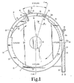
- the orbital cap selection device 10 is shown as comprising a disk 11 rotating within a circular frame 20.
- the disk 11 includes a working surface 11a upon which the articles to be sorted are disposed.
- Disk 11 rotates in the direction of the arrows about a hub 13.
- a frame 20 includes an outer circumferential wall 22 that is integral with the base 21, as shown in FIG. 2.
- bearings B are situated between disk 11 and base 21 so that disk 11 rotates atop the base.
- a drive shaft 14 extends through base 21 and disk 11 and is bolted to disk 11 underneath hub 13.
- Motor M mounted to the underside of base 21, is used to drive shaft 14 to rotate disk 11.
- the orbital cap selection device 10 is supported by mount 17, which is itself mounted to a level surface, such as a table.
- the base 21 of the device is pivotally attached to mount 17 so that the device can be situated at some angle A relative to the horizontal.
- the tilting of the base 21 is about an axis extending from the three o'clock to the nine o'clock position, as defined in FIG. 1.
- the preferred angle A of operation of the working surface 11a for the present embodiment has been found to be about 15 degrees.
- the angle A of the working surface 11a insures that the caps C will enter collector chute 23 (FIGS. 1 and 2) at the lowest portion (six o'clock) of the device.
- the angle A of working surface 11a also aids air ejection assembly 45, which is mounted to the frame 20 rotationally upstream of the 12 o'clock position shown in FIG. 1, in ejecting improperly oriented caps from the guide chute 25 into the working surface 11a.
- the 15 degree angle also assists properly oriented caps exiting the device through the discharge chute assembly 30 (FIG. 1).
- selection device 10 is also tilted at about a five degree angle about an axis from the twelve to the six o'clock positions on device 10.
- frame 20 includes an outer circumferential wall 22 with collector chute 23 and guide chute 25 affixed thereto.
- Collector chute 23 is formed by upper wall 29 and containment shell 24, as illustrated in FIG. 2.
- the lower edge of the containment shell 24 is displaced sufficiently above rotating disk 11 so that a cap C lying flat on the disk can pass under containment shell 24, while a cap standing on end, such as cap C′, cannot pass under the shell into collector chute 23.
- caps randomly disposed on working surface 11a will fall by gravity against the containment shell 24 due to the incline angle A of the rotating disk 11.
- cap C slides underneath the containment shell by action of centrifugal force and is contained on the disk 11 by the rim 12 fixed to and extending around the perimeter of the disk.
- Guide chute 25 is partially defined by guide shell 26, as shown in FIG. 2, which has a lower edge 26a very near the working surface 11a of disk 11. The proximity of the lower edge 26a of guide shell 26 to disk 11 ensures that no other caps may enter the guide chute 25 without having first passed through the collector chute 23, in order to avoid disruption of the procession of caps around guide chute 25.
- the guide chute also includes upper guide wall 27 fixed between the shell 26 and circumferential wall 22 and forming the top of guide chute 25.
- Guide chute 25 extends generally from the nine o'clock position on orbital cap selection device 10, as labeled on FIG. 1, about 180 degrees around the circumference to the three o'clock position. At approximately the 3 o'clock position, the guide chute 25 directs properly oriented caps into the discharge chute assembly 30.
- the guide shell 26 of the guide chute spans from the lower edge 26a to the upper wall 29 from the nine o'clock position to nearly the eleven o'clock position adjacent the sensor assembly 40, to be described herein. At this point, the guide shell 26 is shortened to span from the lower edge 26a to the upper guide wall 27.
- the guide shell 26 includes a gap forming a first ejection opening 48, from about the eleven o'clock to the twelve o'clock position on the guide chute 25, as viewed more clearly in FIG. 1.
- Frame 20 includes deflector rail 28, which is affixed to the upper wall 29 and projects downward from the upper wall 29 toward the working surface 11a.
- Deflector rail 28 is situated inboard of guide chute 25 and has a sharper curvature than the guide chute 25.
- the deflector rail 28 begins at the nine o'clock position and terminates at about the eleven o'clock position adjacent sensor assembly 40.
- the purpose of deflector rail 28 is to insure that caps rotating with and on the central portion of the working surface 11a of disk 11 do not bounce or are not flung by centrifugal force through the first discharge opening 48 into the sensing position directly beneath sensor assembly 40, or into the guide chute just beyond the ejection assembly 45.
- sensor assembly 40 Prior to the midpoint of the path of guide chute 25, or at about the 11 o'clock position on the orbital cap selection device 10, is a sensor assembly 40.
- Sensor assembly 40 is suitably mounted to the outer surface of outer circumferential wall 22 and projects into the body of the selection device 10 through sensor assembly opening 22a (FIG. 2).
- sensor assembly 40 is an optical sensor that transmits a beam of light and receives that beam when it is reflected from a surface.
- sensing opening 43 Directly beneath sensor assembly 40 is a sensing opening 43 in the upper guide wall 27 of the guide chute 25.
- sensor assembly 40 While the operation of this sensor assembly 40 is explained more fully in the co-pending application, Serial No. 101,853, fundamental aspects of its operation will be briefly explained.
- a beam of light transmitted by the sensor assembly 40 is directed through the sensing opening 43 and reflected back through the opening to be received by the sensor.
- sensor assembly 40 is calibrated to sense the closed side of a cap passing under sensing opening 43. If the cap is oriented with the closed side facing disk 11, such as cap C ⁇ in FIG. 2, the cap C ⁇ is permitted to continue in the procession by the sensor assembly 40.
- the sensor assembly 40 generates a signal when an improperly oriented cap is detected. That signal is received by the ejection assembly 45 situated rotationally downstream from sensor assembly 40.
- Ejection assembly 45 includes an airjet nozzle 46 that is connected to a conventional air supply and is mounted to the outer circumferential wall 22.
- the nozzle is arranged to direct a puff of air radially inward across the working surface 11a and slightly downward over rim 12 of disk 11.
- a puff of air is emitted from the airjet nozzle 46. Air from the airjet nozzle acts on the improperly oriented cap as it passes by the nozzle to eject the cap from guide chute 25 through first ejection opening 48 in guide shell 26, pushing it back toward hub 13.
- a critical feature of Applicants' present invention is the addition of a starwheel assembly 50 downstream from the sensor and air ejection assemblies. While the details of this starwheel assembly 50 will be explained more fully herein, it can first be noted, with reference to FIG. 1, that the starwheel assembly 50 is located, in the preferred embodiment, at approximately the 1 o'clock position on the orbital cap selection device 10.
- the starwheel assembly includes a second ejection opening 49 formed in the guide shell 26, in a manner similar to the first ejection opening 48.
- the second ejection opening 49 is situated near the entrance 30a to the discharge chute assembly 30, signified by the junction between guide shell 26 and a guide side wall 38 that forms part of the discharge chute assembly.
- guide side wall 38 is situated slightly above working surface 11a (not shown in the figures), just as guide shell 26 is in the originating portions of guide chute 25.
- Guide side wall 38 keeps properly oriented caps C ⁇ , leaving the starwheel assembly 50, within the guide chute 25, and prevents caps disposed on working surface 11a from improperly entering guide chute 25.
- guide side wall 38 is recessed from containment shell 24.
- the discharge chute assembly 30 includes ramp 32 that is constructed of fairly thin material so that leading edge 32a is flush with working surface 11a.
- a tongue (not shown) projecting from the bottom side of ramp 32 rides within a ramp positioning groove 11b (FIG. 2) around the perimeter of disk 11.
- the ramp 32 is a flattened S-shape so that the ramp can clear rim 12 of the rotating disk 11, while providing a smooth transition for the properly oriented cap C ⁇ from the rotating disk to the discharge chute assembly 30.
- Guide side wall 38 forms an interior wall adjacent to the ramp 32.
- Discharge chute assembly 30 terminates in a discharge opening 36 that can be mated to a chute or track of a separate cap manipulation device, such as a machine that affixes the caps to a bottle or container.
- Discharge assist assembly 39 includes an airjet nozzle 39a that is directed toward ramp 32 so that as the cap C ⁇ is flung onto ramp 32 by the rotation of disk 11, the cap gets an extra assist from a continuous puff of air from airjet nozzle 39a.
- the puff of air from airjet nozzle 39a helps the cap C ⁇ to negotiate the S-shape of ramp 32 until it reaches a point on the ramp at which gravity will help pull the cap through the discharge chute assembly 30 due to the incline of selection device 10.
- the starwheel assembly 50 includes a starwheel 52 that is mounted to the outer circumferential wall 22 of the frame 20.
- a shoulder bolt 53 passes through a bushing 72 (FIG. 5) in a central bore in the starwheel 52, and is threaded or otherwise engaged with mounting bracket 54 on the opposite side of the starwheel 52, that is the radially innermost side of the starwheel closest to the working surface.
- the mounting bracket 54 extends vertically toward the top of the orbital cap selection device 10, where it mates with a mounting block 55.
- the mounting block 55 passes over the starwheel and is suitably affixed to the outer circumferential wall 22, such as by welding or by bolts.
- the mounting bracket 54 is attached to the mounting block 55 by way of a pair of positioning dowels 56 and a fastener 57, such as a threaded bolt.
- the starwheel 52 is oriented so that the starwheel projects through a starwheel opening 60 (FIG. 4) in the upper guide wall 27.
- the starwheel 52 is vertically oriented relative to the working surface 11a of the rotating disk 11, so that the spokes 65 of the starwheel have their closest approach to the working surface at a dimension Z, as shown in FIG. 3. The importance of this dimension will become apparent from the detailed description to follow.
- the second ejection opening 49 in the guide shell 26 is situated radially inboard of the starwheel 52.
- the starwheel is arranged at an angle relative to a tangent defined between the vertical edges of the second ejection opening 49.
- the radial inboard dimension of the upstream portion of the starwheel 52 is at a dimension X from the rim 12 of the rotating disk 11.
- the downstream portion of the starwheel 52 is at a dimension Y from the rim 12, such that the dimension Y is greater than the dimension X.
- the starwheel 52 comprises a plurality of spokes 65 (FIG. 3).
- the number of spokes 65 are determined largely by the diameter of the cap C ⁇ that is to be fed past the starwheel assembly 50.
- the starwheel 52 includes seven spokes evenly spaced around the circumference of the wheel.
- the spokes 65 are uniquely shaped, in that the spokes include a radial edge 66 that lies along a radial line 66a emanating from the shoulder bolt 53 at the center of the starwheel.
- Each of the spokes 65 includes a flat or slightly rounded tip 67 at the free end of radial edge 66.
- the starwheel 52 is oriented so that the radial edge 66 faces the downstream direction.
- each spoke includes a beveled cam surface 70 on the starwheel inboard face 71 that faces the working surface 11a and the second ejection opening 49.
- the geometry of the spokes 65 is important to the function of the orbital cap selection device 10 of the present invention.
- a cap When a cap is properly oriented, such as a cap C ⁇ shown in FIG. 3, the rim R of the cap C ⁇ contacts the sloping edge 69 of the downstream spoke 65d to rotate the starwheel 52 in a counterclockwise direction, as shown by the arrow.
- the upstream spoke 65u enters the open end of the cap C ⁇ , as shown in FIG. 3.
- the upstream portion of the rim R of cap C ⁇ contacts the sloping edge 69 of the upstream spoke 65u to cause the starwheel to rotate further.
- the starwheel assembly 50 is offset from the meanline ML of the procession of caps passing by the starwheel station.
- the meanline ML corresponds generally to a line of centers of the procession of caps.
- the inboard face 71 of the starwheel is canted slightly relative to a tangent to the meanline ML, due to the difference in the distances X and Y as previously described. Consequently, the spokes of the starwheel will not enter a properly oriented cap along a diameter of the cap where the cap opening facing the spokes is greatest. Instead, the spokes will enter the open end of the cap C ⁇ in the outboard hemisphere of the moving cap.
- the length of each spoke measured in terms of the distance Z from the working surface (FIG. 3) must be properly established to provide clearance for the tip 67 of the spoke from the upstream portion of the rim R of the cap as the starwheel rotates. Additional clearance between the spoke and the cap rim R is provided by the chamfered relief edge 68 on the upstream portion of the spoke 65.
- cap C′′′ As the cap C′′′ is delayed at the starwheel assembly station, other caps continue to collect in the guide chute 25 behind the cap C′′′, thereby exerting pressure on the upstream portion of cap C′′′. Moreover, the rotation of the disk 11 beneath the cap C′′′ tries to force the cap downstream. In addition, the spokes of the starwheel themselves urge the cap C′′′ inboard toward the working surface, due to the unique design of the starwheel assembly 50. Since the starwheel 52 is offset outboard of the meanline ML of the procession of caps, it tends to push the cap C′′′ radially inboard. The beveled cam surface 70 allows the tip 67 contacting the cap floor F to be situated further outboard of the meanline ML.
- the beveled cam surface 70 of the starwheel provides an additional radial push as the cap C′′′ starts to gradually move inboard toward the working surface 11a. After the cap has moved sufficiently inboard, the floor F of the cap contacts the cam surface 70, incrementally moving up the cam surface, which movement forces the cap further inboard. It can be noted that at this point, the cap C′′′ has cleared the tip 67 of the spoke and the spoke is allowed to rotate again.
- the self-clearing feature of the starwheel assembly 50 of the present invention is provided as the pressure continues on cap C′′′.
- the pressure of the upstream caps combined with the rotation of the disk below the cap and the urging of the starwheel spokes 65, causes cap C′′′ to gradually "bubble" away from the starwheel 52 toward the second ejection opening 49 in guide shell 26, as shown in FIG. 7.
- the cap C′′′ clears the starwheel, its motion includes a radially inward component, imparted by the starwheel and the upstream caps, and a rotationally downstream component, imparted by the rotating disk 11.
- the second ejection opening 49 is arranged relative to the starwheel 52 so that the improperly oriented cap C′′′ will clear the opening when it is ejected by the starwheel assembly. Once the improperly oriented cap C′′′ slides through the second ejection opening 49, the upstream caps proceed through the starwheel assembly to strike the downstream cap C ⁇ and cause the starwheel 52 to start its freewheel rotation again.
- the second ejection opening 49 must be not only wide enough to accommodate an improperly oriented cap C′′′, it must also be wide enough to allow the ejected cap C′′′ to exit the guide chute 25 after "bubbling" out of the starwheel assembly 50, and while it is being carried downstream by the rotation of the disk 11.
- the overall length of the spokes 65 is also important, so that as the starwheel assembly 50 encounters a string of properly oriented caps, the sloping edge 69 will be continually pushed by the upstream portion of the cap wall W of a properly oriented cap C ⁇ , as shown in FIG. 3, until the starwheel 52 has rotated sufficiently to allow the next spoke to enter the next upstream properly oriented cap. Since an improperly oriented cap C′′′ must slide against the tip 67 and cam edge 68 of a given spoke 65, the starwheel 52 is composed of a material such as LEXAN, that provides a generally smooth, low-friction surface. In addition, a material such as LEXAN has adequate wear resistance to accommodate the long running times of the orbital cap selection 10 and to endure the high free-wheel rotational rates provided by the selection device of the present invention.
- the starwheel assembly 50 is situated downstream from the sensor assembly 40 a distance D.
- the improperly oriented cap essentially stops the flow of caps through the guide chute 25, at least until the cap "bubbles" out through the second ejection opening 49.
- caps passing by the sensor assembly 40 accumulate behind the improperly oriented cap, providing pressure on the cap to force it out through the second ejection opening.
- the distance D that the starwheel assembly 50 is displaced from the sensor assembly 40 is calibrated to allow an adequate accumulation of caps behind the improperly oriented cap, without causing the flow of caps to back-up into the sensor assembly 40 and air ejection assembly 45.
- the starwheel assembly 50 of the present invention represents a means to approach as near 100% cap selection accuracy as is possible with an orbital cap selection device.
- the starwheel assembly 50 is used in conjunction with an upstream cap selection means, such as sensor assembly 40 and air ejection assembly 45.
- an upstream cap selection means such as sensor assembly 40 and air ejection assembly 45.
- high cap feed rates approaching 3000 caps per minute, can be achieved using the sensor assembly 40 as the primary caps selection means.
- the starwheel assembly 50 is a secondary cap selection means that provides additional assurance that improperly oriented caps are not being directed to the discharge chute assembly 30. Since the starwheel 52 of the starwheel assembly 50 is freewheeling, in that its rotation is controlled by pressure from caps flowing through the discharge chute 25, the starwheel assembly 50 does not appreciably slow down properly oriented caps traveling through the discharge chute 25.
- cap feed rate A slight reduction in cap feed rate may be experienced when an improperly oriented cap is detected by the starwheel assembly and ejected back into the working surface 11a of the rotating disk 11 by the bubbling effect of the starwheel sorting.
- the reduction in cap feed rate should not be noticeable.
- the starwheel assembly 50 is used in conjunction with an upstream sensor and selection means, the starwheel assembly 50 can also be used as the only cap selection and ejection means for an orbital cap selection device. In this instance, it is apparent that the high cap feed rates achieved with Applicants' preferred embodiment, will not be achieved when a starwheel assembly 50 alone is providing the selecting and ejection function.
Landscapes
- Engineering & Computer Science (AREA)
- Mechanical Engineering (AREA)
- Sealing Of Jars (AREA)
- Chutes (AREA)
- Feeding Of Articles To Conveyors (AREA)
Applications Claiming Priority (2)
| Application Number | Priority Date | Filing Date | Title |
|---|---|---|---|
| US07/198,831 US4895243A (en) | 1988-05-26 | 1988-05-26 | Starwheel cap selecting apparatus |
| US198831 | 1988-05-26 |
Publications (1)
| Publication Number | Publication Date |
|---|---|
| EP0343922A1 true EP0343922A1 (de) | 1989-11-29 |
Family
ID=22735041
Family Applications (1)
| Application Number | Title | Priority Date | Filing Date |
|---|---|---|---|
| EP89305200A Withdrawn EP0343922A1 (de) | 1988-05-26 | 1989-05-23 | Kapsel-Sortiermaschine mit Sternrad |
Country Status (3)
| Country | Link |
|---|---|
| US (1) | US4895243A (de) |
| EP (1) | EP0343922A1 (de) |
| JP (1) | JPH0228412A (de) |
Cited By (8)
| Publication number | Priority date | Publication date | Assignee | Title |
|---|---|---|---|---|
| EP0782888A3 (de) * | 1995-01-05 | 1998-03-04 | Mauro Lenzi | Vorrichtung zur automatischen Entfernung falsch orientierter Elemente aus einer Zuleitung von Verschlüssen, Steckern oder allgemein konkaven Elementen |
| EP1127834A1 (de) * | 2000-01-28 | 2001-08-29 | Ralf Weidenmüller | Sortiervorrichtung für becherförmige Gegenstände |
| ES2199004A1 (es) * | 2000-11-20 | 2004-02-01 | Diaz Rafael Quiles | Sistema orbital dinamico de alimentacion de piezas. |
| ITTO20100911A1 (it) * | 2010-11-17 | 2011-02-16 | Pesce S R L | Alimentatore meccanico con selezione elettronica multiformato e relativo procedimento di funzionamento |
| CN102070013A (zh) * | 2010-12-13 | 2011-05-25 | 江南大学 | 乳液泵盖自动理盖机 |
| CN102358605A (zh) * | 2011-06-24 | 2012-02-22 | 广州达意隆包装机械股份有限公司 | 一种斜盖理盖机 |
| CN102390699A (zh) * | 2011-10-29 | 2012-03-28 | 广东华盛塑料有限公司 | 盖子自动整理机 |
| DE102011016858A1 (de) * | 2011-04-13 | 2012-10-18 | Krones Aktiengesellschaft | Vorrichtung und Verfahren zum Transportieren von Kunststoffvorformlingen |
Families Citing this family (12)
| Publication number | Priority date | Publication date | Assignee | Title |
|---|---|---|---|---|
| US4995503A (en) * | 1988-05-26 | 1991-02-26 | Graham S Neal | Starwheel cap selecting apparatus |
| CA2082155C (en) * | 1990-05-29 | 2008-04-15 | Krishnaswamy I. Dayalu | Swine pneumonia vaccine and method of preparation |
| US6502688B1 (en) | 2000-10-30 | 2003-01-07 | Pace Packaging Corp. | Method and apparatus for high speed plastic container unscrambling |
| DE102006039091A1 (de) | 2006-08-19 | 2008-02-21 | Khs Ag | Vorrichtung zum Zuführen von Verschlüssen an eine Verschließmaschine |
| JP5156320B2 (ja) * | 2007-09-28 | 2013-03-06 | 有限会社ナカミチ | パーツの整列装置 |
| JP4685899B2 (ja) * | 2008-05-08 | 2011-05-18 | 有限会社ナカミチ | パーツの整列装置 |
| JP5248191B2 (ja) * | 2008-05-10 | 2013-07-31 | 有限会社ナカミチ | パーツの整列供給装置 |
| JP5453700B2 (ja) * | 2009-07-14 | 2014-03-26 | 靜甲株式会社 | 物品整列装置 |
| CN103086145A (zh) * | 2013-01-16 | 2013-05-08 | 南京保立隆包装机械有限公司 | 一种检盖装置 |
| CN104210829B (zh) * | 2014-08-13 | 2017-05-03 | 罗标荣 | 一种节能电动理盖设备 |
| CN108082906A (zh) * | 2017-12-29 | 2018-05-29 | 茂名市腾龙工业皮带有限公司 | 一种棘轮机构 |
| US10273134B1 (en) * | 2018-09-24 | 2019-04-30 | PSR Automation Inc. | Mechanism for orienting packaging elements such as container caps |
Citations (3)
| Publication number | Priority date | Publication date | Assignee | Title |
|---|---|---|---|---|
| FR1440905A (fr) * | 1965-05-06 | 1966-06-03 | Continental Can Co | Appareil pour la distribution de capsules de bouchage orientant ces dernières dans une direction prédéterminée |
| DE2118204A1 (de) * | 1971-04-15 | 1972-11-02 | Aidlin, Samuel Simeon; Aidlin, Stephen Howard; Brooklyn, N.Y. (V.St.A.) | Vorrichtung zur selbsttätigen Ausrichtung und Zuführung von flachen Gegenständen, insbesondere Flaschendeckeln, zu einem Bestimmungsort |
| US4699261A (en) * | 1984-11-29 | 1987-10-13 | Nesin William Z | Closure handling apparatus |
Family Cites Families (10)
| Publication number | Priority date | Publication date | Assignee | Title |
|---|---|---|---|---|
| US2270713A (en) * | 1940-04-06 | 1942-01-20 | Owens Illinois Glass Co | Cap selector |
| US2388405A (en) * | 1944-12-18 | 1945-11-06 | Leopold F Glaude | Automatic feeding device |
| US3065841A (en) * | 1961-01-05 | 1962-11-27 | Anchor Hocking Glass Corp | Selector hopper |
| US3260347A (en) * | 1963-12-09 | 1966-07-12 | Pharmaseal Lab | Machine for orienting small parts |
| US3261442A (en) * | 1964-06-26 | 1966-07-19 | Continental Can Co | Cap turnover device |
| US3570642A (en) * | 1968-12-04 | 1971-03-16 | Continental Can Co | Cap conveying chute with sorting means |
| US3635325A (en) * | 1969-11-24 | 1972-01-18 | Pneumatic Scale Corp | Closure-handling apparatus |
| US3726385A (en) * | 1970-05-15 | 1973-04-10 | Pneumatic Scale Corp | Closure handling apparatus |
| US3811551A (en) * | 1973-01-15 | 1974-05-21 | Phillys Petroleum | Apparatus and method for orienting articles |
| US4709798A (en) * | 1985-03-04 | 1987-12-01 | Michael Herzog | Rotary feeder to orient and feed bottle caps and similar parts |
-
1988
- 1988-05-26 US US07/198,831 patent/US4895243A/en not_active Expired - Lifetime
-
1989
- 1989-05-23 EP EP89305200A patent/EP0343922A1/de not_active Withdrawn
- 1989-05-26 JP JP1134456A patent/JPH0228412A/ja active Pending
Patent Citations (3)
| Publication number | Priority date | Publication date | Assignee | Title |
|---|---|---|---|---|
| FR1440905A (fr) * | 1965-05-06 | 1966-06-03 | Continental Can Co | Appareil pour la distribution de capsules de bouchage orientant ces dernières dans une direction prédéterminée |
| DE2118204A1 (de) * | 1971-04-15 | 1972-11-02 | Aidlin, Samuel Simeon; Aidlin, Stephen Howard; Brooklyn, N.Y. (V.St.A.) | Vorrichtung zur selbsttätigen Ausrichtung und Zuführung von flachen Gegenständen, insbesondere Flaschendeckeln, zu einem Bestimmungsort |
| US4699261A (en) * | 1984-11-29 | 1987-10-13 | Nesin William Z | Closure handling apparatus |
Cited By (12)
| Publication number | Priority date | Publication date | Assignee | Title |
|---|---|---|---|---|
| EP0782888A3 (de) * | 1995-01-05 | 1998-03-04 | Mauro Lenzi | Vorrichtung zur automatischen Entfernung falsch orientierter Elemente aus einer Zuleitung von Verschlüssen, Steckern oder allgemein konkaven Elementen |
| EP1127834A1 (de) * | 2000-01-28 | 2001-08-29 | Ralf Weidenmüller | Sortiervorrichtung für becherförmige Gegenstände |
| ES2199004A1 (es) * | 2000-11-20 | 2004-02-01 | Diaz Rafael Quiles | Sistema orbital dinamico de alimentacion de piezas. |
| ES2199004B1 (es) * | 2000-11-20 | 2005-05-01 | Rafael Quiles Diaz | Sistema orbital dinamico de alimentacion de piezas. |
| ITTO20100911A1 (it) * | 2010-11-17 | 2011-02-16 | Pesce S R L | Alimentatore meccanico con selezione elettronica multiformato e relativo procedimento di funzionamento |
| CN102070013A (zh) * | 2010-12-13 | 2011-05-25 | 江南大学 | 乳液泵盖自动理盖机 |
| CN102070013B (zh) * | 2010-12-13 | 2012-12-26 | 江南大学 | 乳液泵盖自动理盖机 |
| DE102011016858A1 (de) * | 2011-04-13 | 2012-10-18 | Krones Aktiengesellschaft | Vorrichtung und Verfahren zum Transportieren von Kunststoffvorformlingen |
| DE102011016858B4 (de) | 2011-04-13 | 2026-03-26 | Krones Aktiengesellschaft | Vorrichtung und Verfahren zum Transportieren von Kunststoffvorformlingen |
| CN102358605A (zh) * | 2011-06-24 | 2012-02-22 | 广州达意隆包装机械股份有限公司 | 一种斜盖理盖机 |
| CN102390699A (zh) * | 2011-10-29 | 2012-03-28 | 广东华盛塑料有限公司 | 盖子自动整理机 |
| CN102390699B (zh) * | 2011-10-29 | 2014-11-19 | 广东华盛塑料有限公司 | 盖子自动整理机 |
Also Published As
| Publication number | Publication date |
|---|---|
| JPH0228412A (ja) | 1990-01-30 |
| US4895243A (en) | 1990-01-23 |
Similar Documents
| Publication | Publication Date | Title |
|---|---|---|
| US4895243A (en) | Starwheel cap selecting apparatus | |
| US4884678A (en) | Orbital cap selecting and feeding mechanism | |
| US4995503A (en) | Starwheel cap selecting apparatus | |
| US4610345A (en) | Method and apparatus for orienting and delivering dispenser cap assemblies | |
| US3392816A (en) | Method of and apparatus for unscrambling articles in bulk | |
| EP0778231B1 (de) | Einrichtung zum Ausrichten und Zuführen von Teilen | |
| US3330403A (en) | Method and apparatus for feeding articles | |
| US10964148B2 (en) | Coin sorting system coin chute | |
| JPH02126387A (ja) | コイン・ソーター | |
| JPH11507459A (ja) | 硬貨計数選別機 | |
| JPH08180233A (ja) | 環状の選別区間により硬貨を選別および/または数えるための装置 | |
| JPH01288514A (ja) | 形成品引渡し装置 | |
| CN110902284A (zh) | 一种理瓶盘设备及含有其的饮料瓶回收系统 | |
| US3826405A (en) | Method of orienting articles | |
| US4453626A (en) | Vibratory feeding apparatus | |
| US3300022A (en) | Closure handling apparatus | |
| US4088143A (en) | Apparatus for feeding and orienting coins | |
| EP1250276B1 (de) | Vorrichtung und verfahren zum sortieren von gegenständen | |
| CN101263531B (zh) | 硬币处理设备 | |
| US4094412A (en) | Rolling method of sorting particulate articles | |
| JP2008293447A (ja) | コインホッパ | |
| US5186305A (en) | Apparatus and methods for feeding container crowns and similar articles at high through-put rates | |
| US3578140A (en) | Closure feeding apparatus | |
| FI94380B (fi) | Laitteisto kiekkomaisten kappaleiden, etenkin kolikoiden erottelemiseksi | |
| US5464089A (en) | Electromagnet crown sorting and un-jamming device |
Legal Events
| Date | Code | Title | Description |
|---|---|---|---|
| PUAI | Public reference made under article 153(3) epc to a published international application that has entered the european phase |
Free format text: ORIGINAL CODE: 0009012 |
|
| AK | Designated contracting states |
Kind code of ref document: A1 Designated state(s): AT BE CH DE ES FR GB GR IT LI LU NL SE |
|
| 17P | Request for examination filed |
Effective date: 19891127 |
|
| STAA | Information on the status of an ep patent application or granted ep patent |
Free format text: STATUS: THE APPLICATION HAS BEEN WITHDRAWN |
|
| 18W | Application withdrawn |
Withdrawal date: 19910111 |
|
| R18W | Application withdrawn (corrected) |
Effective date: 19910111 |