EP0343660A2 - Dispositif de régulation de la puissance thermique d'une chaudière combustible solide - Google Patents
Dispositif de régulation de la puissance thermique d'une chaudière combustible solide Download PDFInfo
- Publication number
- EP0343660A2 EP0343660A2 EP89109433A EP89109433A EP0343660A2 EP 0343660 A2 EP0343660 A2 EP 0343660A2 EP 89109433 A EP89109433 A EP 89109433A EP 89109433 A EP89109433 A EP 89109433A EP 0343660 A2 EP0343660 A2 EP 0343660A2
- Authority
- EP
- European Patent Office
- Prior art keywords
- boiler
- temperature
- supply air
- control device
- fan
- Prior art date
- Legal status (The legal status is an assumption and is not a legal conclusion. Google has not performed a legal analysis and makes no representation as to the accuracy of the status listed.)
- Withdrawn
Links
- 239000004449 solid propellant Substances 0.000 title claims abstract description 10
- 230000001105 regulatory effect Effects 0.000 title claims abstract description 4
- 230000001419 dependent effect Effects 0.000 claims abstract description 4
- 238000010438 heat treatment Methods 0.000 claims description 17
- 239000003344 environmental pollutant Substances 0.000 claims description 3
- 231100000719 pollutant Toxicity 0.000 claims description 3
- 238000007872 degassing Methods 0.000 claims description 2
- 239000007789 gas Substances 0.000 description 8
- 238000000034 method Methods 0.000 description 3
- UGFAIRIUMAVXCW-UHFFFAOYSA-N Carbon monoxide Chemical compound [O+]#[C-] UGFAIRIUMAVXCW-UHFFFAOYSA-N 0.000 description 2
- 238000002485 combustion reaction Methods 0.000 description 2
- 239000000446 fuel Substances 0.000 description 2
- XLYOFNOQVPJJNP-UHFFFAOYSA-N water Substances O XLYOFNOQVPJJNP-UHFFFAOYSA-N 0.000 description 2
- 101100390736 Danio rerio fign gene Proteins 0.000 description 1
- 101100390738 Mus musculus Fign gene Proteins 0.000 description 1
- QVGXLLKOCUKJST-UHFFFAOYSA-N atomic oxygen Chemical compound [O] QVGXLLKOCUKJST-UHFFFAOYSA-N 0.000 description 1
- 229910002091 carbon monoxide Inorganic materials 0.000 description 1
- 239000003546 flue gas Substances 0.000 description 1
- 238000012544 monitoring process Methods 0.000 description 1
- 229910052760 oxygen Inorganic materials 0.000 description 1
- 239000001301 oxygen Substances 0.000 description 1
- 238000002791 soaking Methods 0.000 description 1
- 230000002277 temperature effect Effects 0.000 description 1
- 230000007704 transition Effects 0.000 description 1
- 230000001960 triggered effect Effects 0.000 description 1
- 239000002023 wood Substances 0.000 description 1
Images

Classifications
-
- F—MECHANICAL ENGINEERING; LIGHTING; HEATING; WEAPONS; BLASTING
- F23—COMBUSTION APPARATUS; COMBUSTION PROCESSES
- F23N—REGULATING OR CONTROLLING COMBUSTION
- F23N1/00—Regulating fuel supply
- F23N1/02—Regulating fuel supply conjointly with air supply
- F23N1/022—Regulating fuel supply conjointly with air supply using electronic means
-
- F—MECHANICAL ENGINEERING; LIGHTING; HEATING; WEAPONS; BLASTING
- F23—COMBUSTION APPARATUS; COMBUSTION PROCESSES
- F23N—REGULATING OR CONTROLLING COMBUSTION
- F23N2225/00—Measuring
- F23N2225/08—Measuring temperature
-
- F—MECHANICAL ENGINEERING; LIGHTING; HEATING; WEAPONS; BLASTING
- F23—COMBUSTION APPARATUS; COMBUSTION PROCESSES
- F23N—REGULATING OR CONTROLLING COMBUSTION
- F23N2225/00—Measuring
- F23N2225/08—Measuring temperature
- F23N2225/10—Measuring temperature stack temperature
-
- F—MECHANICAL ENGINEERING; LIGHTING; HEATING; WEAPONS; BLASTING
- F23—COMBUSTION APPARATUS; COMBUSTION PROCESSES
- F23N—REGULATING OR CONTROLLING COMBUSTION
- F23N2225/00—Measuring
- F23N2225/08—Measuring temperature
- F23N2225/12—Measuring temperature room temperature
-
- F—MECHANICAL ENGINEERING; LIGHTING; HEATING; WEAPONS; BLASTING
- F23—COMBUSTION APPARATUS; COMBUSTION PROCESSES
- F23N—REGULATING OR CONTROLLING COMBUSTION
- F23N2225/00—Measuring
- F23N2225/08—Measuring temperature
- F23N2225/13—Measuring temperature outdoor temperature
-
- F—MECHANICAL ENGINEERING; LIGHTING; HEATING; WEAPONS; BLASTING
- F23—COMBUSTION APPARATUS; COMBUSTION PROCESSES
- F23N—REGULATING OR CONTROLLING COMBUSTION
- F23N2225/00—Measuring
- F23N2225/08—Measuring temperature
- F23N2225/18—Measuring temperature feedwater temperature
-
- F—MECHANICAL ENGINEERING; LIGHTING; HEATING; WEAPONS; BLASTING
- F23—COMBUSTION APPARATUS; COMBUSTION PROCESSES
- F23N—REGULATING OR CONTROLLING COMBUSTION
- F23N2225/00—Measuring
- F23N2225/08—Measuring temperature
- F23N2225/19—Measuring temperature outlet temperature water heat-exchanger
-
- F—MECHANICAL ENGINEERING; LIGHTING; HEATING; WEAPONS; BLASTING
- F23—COMBUSTION APPARATUS; COMBUSTION PROCESSES
- F23N—REGULATING OR CONTROLLING COMBUSTION
- F23N2227/00—Ignition or checking
-
- F—MECHANICAL ENGINEERING; LIGHTING; HEATING; WEAPONS; BLASTING
- F23—COMBUSTION APPARATUS; COMBUSTION PROCESSES
- F23N—REGULATING OR CONTROLLING COMBUSTION
- F23N2231/00—Fail safe
-
- F—MECHANICAL ENGINEERING; LIGHTING; HEATING; WEAPONS; BLASTING
- F23—COMBUSTION APPARATUS; COMBUSTION PROCESSES
- F23N—REGULATING OR CONTROLLING COMBUSTION
- F23N2233/00—Ventilators
- F23N2233/06—Ventilators at the air intake
- F23N2233/08—Ventilators at the air intake with variable speed
-
- F—MECHANICAL ENGINEERING; LIGHTING; HEATING; WEAPONS; BLASTING
- F23—COMBUSTION APPARATUS; COMBUSTION PROCESSES
- F23N—REGULATING OR CONTROLLING COMBUSTION
- F23N2239/00—Fuels
-
- F—MECHANICAL ENGINEERING; LIGHTING; HEATING; WEAPONS; BLASTING
- F23—COMBUSTION APPARATUS; COMBUSTION PROCESSES
- F23N—REGULATING OR CONTROLLING COMBUSTION
- F23N2239/00—Fuels
- F23N2239/02—Solid fuels
-
- F—MECHANICAL ENGINEERING; LIGHTING; HEATING; WEAPONS; BLASTING
- F23—COMBUSTION APPARATUS; COMBUSTION PROCESSES
- F23N—REGULATING OR CONTROLLING COMBUSTION
- F23N2241/00—Applications
- F23N2241/06—Space-heating and heating water
Definitions
- the invention relates to a device for regulating the heat output of a solid fuel boiler by temperature-dependent regulation of the amount of air supplied to the boiler by a supply air blower.
- the invention has for its object to provide a device which allows the good, in particular environmentally friendly, combustion values already achieved in the nominal load operation to be transferred to the low-load phase and in particular to counter the highly undesirable pollutant emissions in the event of a reduction in performance.
- the supply air blower is connected to a control device which ensures only a very slow change in the supply air quantity supplied to the boiler.
- the control device is designed such that after reaching a predetermined temperature of the boiler
- the time constant can, for example, be in the order of 5 to 30 minutes.
- the device according to the invention works particularly environmentally friendly, while at the same time maintaining a high degree of efficiency and utilization.
- the control device provided preferably determines the speed of the supply air blower, although it is also possible in principle to let the control device act on a mechanical air control device for influencing the amount of air introduced into the boiler.
- the boiler temperature, the heating circuit flow temperature, the boiler return temperature, the flue gas temperature and the outside temperature can be taken into account as influencing factors for the control of the air volume supplied to the boiler individually, in combination or in any combination of parts.
- a safety temperature limiter and / or a door contact switch by means of which the fan is switched off when a predetermined maximum temperature is exceeded or the filling shaft degassing or the boiler door is opened, are expediently located in series with a fan motor which drives the supply air fan.
- Additional modules can be connected to the control device, in particular one or more motor mixers assigned to the heating circuit and / or one or more additional buffer stores connected to the heating circuit, which are logically loaded or unloaded via a motor mixer.
- a solid fuel boiler is designated by 10 in total.
- the boiler 10 has a fuel filling chamber 11, into which solid fuel, in particular lumber, can be introduced after opening a filling door 12.
- a supply air blower 13 is mounted on the filling door 12. Supply air can be blown into the fuel filling chamber 11 by means of the fan 13.
- the flow connection 14 is connected via a line 17 to the inlet of any heat exchanger 18, the outlet of which via lines 19 and 20 the return port 16 is connected. It goes without saying that a plurality of such heat exchangers can also be provided instead of one heat exchanger.
- a heating or circulation pump 21 is located in line 17.
- a service water tank 24 is also connected to the flow and return connections 14 and 16 via lines 22, 23 and lines 17, 20.
- a storage tank charging pump 25 is located in line 23.
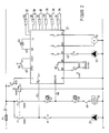
- a control device provided with a display or display field 26 is illustrated at 27 in FIG. 1.
- Inputs of the control unit 27 are via a line 28 to a flow sensor 29 determining the flow temperature (FIG. 2), via a line 30 to a boiler return sensor 31 determining the return temperature, via a line 32 to a boiler sensor 33 monitoring the boiler temperature, via a line 34 to an exhaust gas sensor 35 which determines the exhaust gas temperature, via a line 36 to a room sensor 37 which determines the room temperature and via a line 38 to an external sensor 39 which monitors the outside temperature.
- Outputs of the control device 27 are connected via a line 40 to the supply air blower 13, via a line 41 to the heating pump 21 and via a line 42 to the storage tank charging pump 25.
- a line 43 connects the control unit 27 to a remote or home display 44.
- the control unit 27 is connected to the boiler 10 via a remote ignition or start line 45.
- the heating system including the control device 27 is supplied with power from mains lines L and N (FIG. 2) via a mains switch S1 and a mains input fuse F1. If the mains switch S1 is in the OFF position, a burner which may be connected to an OIL / GAS output is permanently enabled, since this output is connected to a normally closed contact 46. In this way, the burner of a possibly connected oil / gas boiler can be operated. In the OFF position of the power switch S1, the power supply for the control device 27 and all consumers connected to this device are switched off. In the ON position of the power switch S1, the control device 27 is switched on.
- an operating mode selector switch S2 two operating modes, namely manual mode and automatic mode, can be selected.
- the control device 27 processes the measured values of the connected sensors, and it controls the speed of the supply air fan 13 as a function of these measured values. If the selector switch S2 is set to the "manual" position, the supply air fan 13 runs at maximum speed. The burner is constantly blocked.
- a boiler temperature monitor 47 in manual mode which is permanently set to a predetermined boiler temperature and switches off the blower 13 when this temperature is exceeded.
- a safety temperature limiter 48 and a door contact switch 49 in series with the blower motor.
- the fan is always switched off via the safety temperature limiter 48 as soon as a predetermined maximum temperature (e.g. 110 ° C) is exceeded.
- the door contact switch 49 ensures that the fan 13 is switched off automatically when the filling shaft vent or the filling door 12 of the boiler 10 is opened.
- the setpoint of the boiler temperature is expediently determined from the outside temperature and the slope.
- the slope can in turn preferably be set on the control device 27.
- the return sensor 31 is optional, however; if there is no return sensor, the return temperature is disregarded.
- the start process of the boiler control is triggered by actuating a start button 50.
- a predetermined limit value minimum boiler limit
- the supply air blower 13 is made to run at the maximum speed for a period of time determined by a timer. If the minimum boiler temperature is not exceeded during this period, the fan 13 is switched off. If, on the other hand, the minimum boiler limit is exceeded during the start time period predetermined by the timer, normal control mode begins.
- the heating pump 21 is switched on as soon as the boiler temperature exceeds a minimum temperature. If the boiler temperature drops again, pumps 21 and 25 are switched off.
- the fan speed is expediently determined by the deviation between the setpoint and the actual value of the boiler temperature. If the actual value of the boiler temperature is below the target value by at least a predetermined difference, the fan 13 runs at maximum speed. If the actual boiler temperature rises and the deviation between the setpoint and actual value is smaller than the predetermined difference, the fan speed is reduced until the fan 13 is stopped after reaching the setpoint temperature. The speed is only slow, i.e. with high time constant, changed.
- the maximum limitation of the boiler temperature should react in a damped manner, such that the fan speed is throttled from a certain boiler temperature until the fan 13 comes to a standstill at a maximum temperature. If the latter is not possible in individual cases, the maximum limitation must be provided with a hysteresis of a few ° C.
- the exhaust gas temperature preferably also affects the speed of the fan 13. If a specified exhaust gas temperature limit is exceeded, the blower speed is reduced reduced with a time delay. On the other hand, if the exhaust gas temperature falls below a predetermined minimum exhaust gas temperature limit, the fan speed is increased with a time delay.
- the timer mentioned above is started again. If the minimum boiler temperature falls below, the apartment display 44 is expediently put into operation.
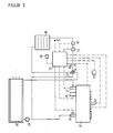
- the feed line 17 and the return line 19 are connected to a motor mixer 51.
- the control device 27 can expediently be designed for weather-dependent flow temperature control and control the mixer 51 to regulate the flow temperature.
- the outside temperature is taken over by the outside sensor 39 which is present anyway.
- the room sensor 37 or a remote control can be connected optionally.
- the controller output line for driving the motor mixer 51 is shown at 52.
- 59 is a flow sensor.
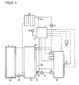
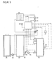
- an additional buffer store 53 is located after the boiler 10, as is known per se from DE-OS 36 24 864.
- a circulation pump 54 and a motor mixer 55 are assigned to the buffer store 53.
- the circulation pump 54 is located in the return line 20.
- the motor mixer 55 is connected to this return line 20 and a connecting line 56 between a lower connecting line 57 and an upper connecting line 58.
- the motor mixer 55 is expediently controlled by the control device 27 as a function of the difference between the boiler temperature and the boiler return temperature.
- both the mixer 51 according to FIG. 3 and the mixer 55 according to FIG. 4 are present. Both mixers are advantageously controlled by the control unit 27.
Landscapes
- Engineering & Computer Science (AREA)
- Chemical & Material Sciences (AREA)
- Combustion & Propulsion (AREA)
- Mechanical Engineering (AREA)
- General Engineering & Computer Science (AREA)
- Air Supply (AREA)
Applications Claiming Priority (2)
| Application Number | Priority Date | Filing Date | Title |
|---|---|---|---|
| DE3817598A DE3817598A1 (de) | 1988-05-24 | 1988-05-24 | Vorrichtung zum regeln der verbrennungsleistung eines feststoffheizkessels |
| DE3817598 | 1988-05-24 |
Publications (2)
| Publication Number | Publication Date |
|---|---|
| EP0343660A2 true EP0343660A2 (fr) | 1989-11-29 |
| EP0343660A3 EP0343660A3 (fr) | 1990-09-26 |
Family
ID=6355003
Family Applications (1)
| Application Number | Title | Priority Date | Filing Date |
|---|---|---|---|
| EP19890109433 Withdrawn EP0343660A3 (fr) | 1988-05-24 | 1989-05-24 | Dispositif de régulation de la puissance thermique d'une chaudière combustible solide |
Country Status (2)
| Country | Link |
|---|---|
| EP (1) | EP0343660A3 (fr) |
| DE (1) | DE3817598A1 (fr) |
Cited By (2)
| Publication number | Priority date | Publication date | Assignee | Title |
|---|---|---|---|---|
| EP0624756A1 (fr) * | 1993-05-14 | 1994-11-17 | Haiko Paul Künzel | Procédé pour commander une installation de chauffage équipée avec une chaudière à combustible solide |
| FR2976051A1 (fr) * | 2011-05-30 | 2012-12-07 | Electricite De France | Dispositif de pilotage d'un poele a granules |
Families Citing this family (1)
| Publication number | Priority date | Publication date | Assignee | Title |
|---|---|---|---|---|
| DE4408801C2 (de) * | 1993-03-16 | 2002-10-17 | Ulrich Dreizler | Gasgebläsebrenner |
Family Cites Families (10)
| Publication number | Priority date | Publication date | Assignee | Title |
|---|---|---|---|---|
| US1891100A (en) * | 1929-10-30 | 1932-12-13 | Frank X Lauterbur | Furnace and furnace draft control |
| CH192531A (de) * | 1937-01-14 | 1937-08-31 | Willi Alois | Feuerreguliereinrichtung an Zentralheizungskesseln für Kohlenfeuerung. |
| US2285226A (en) * | 1941-04-29 | 1942-06-02 | Gen Electric | Fluid flow control |
| DK145685C (da) * | 1976-04-26 | 1983-08-08 | Lars Leksander Slyn Joergensen | Fremgangsmaade og apparat til regulering af forbraendingen i et fyr |
| LU79664A1 (de) * | 1978-05-16 | 1979-12-06 | M Olieman | Verfahren und vorrichtung zur regelung von kesselfeuerungsanlagen |
| DE3025966C2 (de) * | 1980-07-09 | 1983-11-24 | Buderus Ag, 6330 Wetzlar | Selbsttätige Regelung eines Saugzugventilators und einer Frischluftklappe an Heizkesseln zur Verfeuerung fester Brennstoffe |
| DE3106015C2 (de) * | 1981-02-18 | 1985-08-01 | "HDG" Entwicklungs- und Patentverwertungsgesellschaft mbH, Wald, Steiermark | Verfahren zum Betreiben eines Heizkessel, der mit Festbrennstoff und mit Öl oder Gas beheizbar ist und Vorrichtung zur Durchführung des Verfahrens |
| AT399767B (de) * | 1985-02-07 | 1995-07-25 | Basten Gert | Einrichtung zur eliminierung von atmosphärischen beeinflussungen auf das zugverhalten eines schornsteines |
| KR910002740B1 (ko) * | 1986-02-22 | 1991-05-03 | 린나이 가부시기가이샤 | 연소제어장치 |
| CH673699A5 (en) * | 1986-09-12 | 1990-03-30 | Tiba Kochherd & App Ag | Combustion air regulation system for solid fuel boiler - with separate regulation of total quantity of air and primary secondary air ratio |
-
1988
- 1988-05-24 DE DE3817598A patent/DE3817598A1/de not_active Withdrawn
-
1989
- 1989-05-24 EP EP19890109433 patent/EP0343660A3/fr not_active Withdrawn
Cited By (2)
| Publication number | Priority date | Publication date | Assignee | Title |
|---|---|---|---|---|
| EP0624756A1 (fr) * | 1993-05-14 | 1994-11-17 | Haiko Paul Künzel | Procédé pour commander une installation de chauffage équipée avec une chaudière à combustible solide |
| FR2976051A1 (fr) * | 2011-05-30 | 2012-12-07 | Electricite De France | Dispositif de pilotage d'un poele a granules |
Also Published As
| Publication number | Publication date |
|---|---|
| DE3817598A1 (de) | 1989-11-30 |
| EP0343660A3 (fr) | 1990-09-26 |
Similar Documents
| Publication | Publication Date | Title |
|---|---|---|
| EP0614046A1 (fr) | Dispositif de commande et réglage pour des automates à brûleur à gaz d'installations de chauffage | |
| DE3700084C2 (fr) | ||
| EP0484280B1 (fr) | Installation pour la purification de l'air chargé de polluants | |
| EP2210044B1 (fr) | Procédé de régulation d'un dispositif de chauffe à combustible solide | |
| DE4316182A1 (de) | Verfahren zum Steuern und/oder Regeln einer mit einem Feststoffkessel ausgerüsteten Heizungsanlage sowie Vorrichtung zur Durchführung des Verfahrens | |
| EP0614047B1 (fr) | Dispositif électronique de commande et de réglage pour des brûleurs à gaz d'installations de chauffage | |
| EP0343660A2 (fr) | Dispositif de régulation de la puissance thermique d'une chaudière combustible solide | |
| DE4408801C2 (de) | Gasgebläsebrenner | |
| DE3517902C2 (fr) | ||
| DE2910294C2 (de) | Temperaturregler | |
| EP2275748B1 (fr) | Procédé de fonctionnement d'une installation de chauffage et installation de chauffage | |
| EP0556736A1 (fr) | Procédé pour la commande d'une chaudière | |
| DE3538934C2 (fr) | ||
| DE19714073A1 (de) | Wirbelschichtanlage, insbesondere für Schlamm | |
| DE19601517A1 (de) | Regelung eines Gasheizgeräts | |
| EP0544622A1 (fr) | Installation à chaudières à deux combustibles d'un chauffage central avec une chaudière à bois et une chaudière à huile | |
| DE2918360A1 (de) | Verfahren zur regelung von kesselfeuerungsanlagen | |
| DE68914121T2 (de) | Automatisches Regel-Verfahren und Einrichtung für einen Festbrennstoff-Heizkessel mit unterbrochener Ladung und erzwungenem Zug, insbesondere für Holz-Heizkessel. | |
| EP0151460A2 (fr) | Installation de chauffage | |
| AT412504B (de) | Verfahren zum laden eines speichers einer heizungsanlage | |
| EP4204735B1 (fr) | Dispositif électronique de commande en boucle fermée pour cheminées comprenant un système de combustion inférieur | |
| AT397854B (de) | Verfahren zur steuerung eines kessels | |
| AT403414B (de) | Verfahren zur kesselrücklauftemperatur-regelung | |
| DE3731318C2 (fr) | ||
| DE4413186B4 (de) | Verfahren zur Kesselrücklauftemperatur-Regelung |
Legal Events
| Date | Code | Title | Description |
|---|---|---|---|
| PUAI | Public reference made under article 153(3) epc to a published international application that has entered the european phase |
Free format text: ORIGINAL CODE: 0009012 |
|
| AK | Designated contracting states |
Kind code of ref document: A2 Designated state(s): AT BE CH DE ES FR GB GR IT LI LU NL SE |
|
| PUAL | Search report despatched |
Free format text: ORIGINAL CODE: 0009013 |
|
| AK | Designated contracting states |
Kind code of ref document: A3 Designated state(s): AT BE CH DE ES FR GB GR IT LI LU NL SE |
|
| 17P | Request for examination filed |
Effective date: 19901231 |
|
| 17Q | First examination report despatched |
Effective date: 19920625 |
|
| STAA | Information on the status of an ep patent application or granted ep patent |
Free format text: STATUS: THE APPLICATION IS DEEMED TO BE WITHDRAWN |
|
| 18D | Application deemed to be withdrawn |
Effective date: 19930928 |