EP0343660A2 - Thermal power regulating apparatus for a solid fuel boiler - Google Patents
Thermal power regulating apparatus for a solid fuel boiler Download PDFInfo
- Publication number
- EP0343660A2 EP0343660A2 EP89109433A EP89109433A EP0343660A2 EP 0343660 A2 EP0343660 A2 EP 0343660A2 EP 89109433 A EP89109433 A EP 89109433A EP 89109433 A EP89109433 A EP 89109433A EP 0343660 A2 EP0343660 A2 EP 0343660A2
- Authority
- EP
- European Patent Office
- Prior art keywords
- boiler
- temperature
- supply air
- control device
- fan
- Prior art date
- Legal status (The legal status is an assumption and is not a legal conclusion. Google has not performed a legal analysis and makes no representation as to the accuracy of the status listed.)
- Withdrawn
Links
- 239000004449 solid propellant Substances 0.000 title claims abstract description 10
- 230000001105 regulatory effect Effects 0.000 title claims abstract description 4
- 230000001419 dependent effect Effects 0.000 claims abstract description 4
- 238000010438 heat treatment Methods 0.000 claims description 17
- 239000003344 environmental pollutant Substances 0.000 claims description 3
- 231100000719 pollutant Toxicity 0.000 claims description 3
- 238000007872 degassing Methods 0.000 claims description 2
- 239000007789 gas Substances 0.000 description 8
- 238000000034 method Methods 0.000 description 3
- UGFAIRIUMAVXCW-UHFFFAOYSA-N Carbon monoxide Chemical compound [O+]#[C-] UGFAIRIUMAVXCW-UHFFFAOYSA-N 0.000 description 2
- 238000002485 combustion reaction Methods 0.000 description 2
- 239000000446 fuel Substances 0.000 description 2
- XLYOFNOQVPJJNP-UHFFFAOYSA-N water Substances O XLYOFNOQVPJJNP-UHFFFAOYSA-N 0.000 description 2
- 101100390736 Danio rerio fign gene Proteins 0.000 description 1
- 101100390738 Mus musculus Fign gene Proteins 0.000 description 1
- QVGXLLKOCUKJST-UHFFFAOYSA-N atomic oxygen Chemical compound [O] QVGXLLKOCUKJST-UHFFFAOYSA-N 0.000 description 1
- 229910002091 carbon monoxide Inorganic materials 0.000 description 1
- 239000003546 flue gas Substances 0.000 description 1
- 238000012544 monitoring process Methods 0.000 description 1
- 229910052760 oxygen Inorganic materials 0.000 description 1
- 239000001301 oxygen Substances 0.000 description 1
- 238000002791 soaking Methods 0.000 description 1
- 230000002277 temperature effect Effects 0.000 description 1
- 230000007704 transition Effects 0.000 description 1
- 230000001960 triggered effect Effects 0.000 description 1
- 239000002023 wood Substances 0.000 description 1
Images

Classifications
-
- F—MECHANICAL ENGINEERING; LIGHTING; HEATING; WEAPONS; BLASTING
- F23—COMBUSTION APPARATUS; COMBUSTION PROCESSES
- F23N—REGULATING OR CONTROLLING COMBUSTION
- F23N1/00—Regulating fuel supply
- F23N1/02—Regulating fuel supply conjointly with air supply
- F23N1/022—Regulating fuel supply conjointly with air supply using electronic means
-
- F—MECHANICAL ENGINEERING; LIGHTING; HEATING; WEAPONS; BLASTING
- F23—COMBUSTION APPARATUS; COMBUSTION PROCESSES
- F23N—REGULATING OR CONTROLLING COMBUSTION
- F23N2225/00—Measuring
- F23N2225/08—Measuring temperature
-
- F—MECHANICAL ENGINEERING; LIGHTING; HEATING; WEAPONS; BLASTING
- F23—COMBUSTION APPARATUS; COMBUSTION PROCESSES
- F23N—REGULATING OR CONTROLLING COMBUSTION
- F23N2225/00—Measuring
- F23N2225/08—Measuring temperature
- F23N2225/10—Measuring temperature stack temperature
-
- F—MECHANICAL ENGINEERING; LIGHTING; HEATING; WEAPONS; BLASTING
- F23—COMBUSTION APPARATUS; COMBUSTION PROCESSES
- F23N—REGULATING OR CONTROLLING COMBUSTION
- F23N2225/00—Measuring
- F23N2225/08—Measuring temperature
- F23N2225/12—Measuring temperature room temperature
-
- F—MECHANICAL ENGINEERING; LIGHTING; HEATING; WEAPONS; BLASTING
- F23—COMBUSTION APPARATUS; COMBUSTION PROCESSES
- F23N—REGULATING OR CONTROLLING COMBUSTION
- F23N2225/00—Measuring
- F23N2225/08—Measuring temperature
- F23N2225/13—Measuring temperature outdoor temperature
-
- F—MECHANICAL ENGINEERING; LIGHTING; HEATING; WEAPONS; BLASTING
- F23—COMBUSTION APPARATUS; COMBUSTION PROCESSES
- F23N—REGULATING OR CONTROLLING COMBUSTION
- F23N2225/00—Measuring
- F23N2225/08—Measuring temperature
- F23N2225/18—Measuring temperature feedwater temperature
-
- F—MECHANICAL ENGINEERING; LIGHTING; HEATING; WEAPONS; BLASTING
- F23—COMBUSTION APPARATUS; COMBUSTION PROCESSES
- F23N—REGULATING OR CONTROLLING COMBUSTION
- F23N2225/00—Measuring
- F23N2225/08—Measuring temperature
- F23N2225/19—Measuring temperature outlet temperature water heat-exchanger
-
- F—MECHANICAL ENGINEERING; LIGHTING; HEATING; WEAPONS; BLASTING
- F23—COMBUSTION APPARATUS; COMBUSTION PROCESSES
- F23N—REGULATING OR CONTROLLING COMBUSTION
- F23N2227/00—Ignition or checking
-
- F—MECHANICAL ENGINEERING; LIGHTING; HEATING; WEAPONS; BLASTING
- F23—COMBUSTION APPARATUS; COMBUSTION PROCESSES
- F23N—REGULATING OR CONTROLLING COMBUSTION
- F23N2231/00—Fail safe
-
- F—MECHANICAL ENGINEERING; LIGHTING; HEATING; WEAPONS; BLASTING
- F23—COMBUSTION APPARATUS; COMBUSTION PROCESSES
- F23N—REGULATING OR CONTROLLING COMBUSTION
- F23N2233/00—Ventilators
- F23N2233/06—Ventilators at the air intake
- F23N2233/08—Ventilators at the air intake with variable speed
-
- F—MECHANICAL ENGINEERING; LIGHTING; HEATING; WEAPONS; BLASTING
- F23—COMBUSTION APPARATUS; COMBUSTION PROCESSES
- F23N—REGULATING OR CONTROLLING COMBUSTION
- F23N2239/00—Fuels
-
- F—MECHANICAL ENGINEERING; LIGHTING; HEATING; WEAPONS; BLASTING
- F23—COMBUSTION APPARATUS; COMBUSTION PROCESSES
- F23N—REGULATING OR CONTROLLING COMBUSTION
- F23N2239/00—Fuels
- F23N2239/02—Solid fuels
-
- F—MECHANICAL ENGINEERING; LIGHTING; HEATING; WEAPONS; BLASTING
- F23—COMBUSTION APPARATUS; COMBUSTION PROCESSES
- F23N—REGULATING OR CONTROLLING COMBUSTION
- F23N2241/00—Applications
- F23N2241/06—Space-heating and heating water
Definitions
- the invention relates to a device for regulating the heat output of a solid fuel boiler by temperature-dependent regulation of the amount of air supplied to the boiler by a supply air blower.
- the invention has for its object to provide a device which allows the good, in particular environmentally friendly, combustion values already achieved in the nominal load operation to be transferred to the low-load phase and in particular to counter the highly undesirable pollutant emissions in the event of a reduction in performance.
- the supply air blower is connected to a control device which ensures only a very slow change in the supply air quantity supplied to the boiler.
- the control device is designed such that after reaching a predetermined temperature of the boiler
- the time constant can, for example, be in the order of 5 to 30 minutes.
- the device according to the invention works particularly environmentally friendly, while at the same time maintaining a high degree of efficiency and utilization.
- the control device provided preferably determines the speed of the supply air blower, although it is also possible in principle to let the control device act on a mechanical air control device for influencing the amount of air introduced into the boiler.
- the boiler temperature, the heating circuit flow temperature, the boiler return temperature, the flue gas temperature and the outside temperature can be taken into account as influencing factors for the control of the air volume supplied to the boiler individually, in combination or in any combination of parts.
- a safety temperature limiter and / or a door contact switch by means of which the fan is switched off when a predetermined maximum temperature is exceeded or the filling shaft degassing or the boiler door is opened, are expediently located in series with a fan motor which drives the supply air fan.
- Additional modules can be connected to the control device, in particular one or more motor mixers assigned to the heating circuit and / or one or more additional buffer stores connected to the heating circuit, which are logically loaded or unloaded via a motor mixer.
- a solid fuel boiler is designated by 10 in total.
- the boiler 10 has a fuel filling chamber 11, into which solid fuel, in particular lumber, can be introduced after opening a filling door 12.
- a supply air blower 13 is mounted on the filling door 12. Supply air can be blown into the fuel filling chamber 11 by means of the fan 13.
- the flow connection 14 is connected via a line 17 to the inlet of any heat exchanger 18, the outlet of which via lines 19 and 20 the return port 16 is connected. It goes without saying that a plurality of such heat exchangers can also be provided instead of one heat exchanger.
- a heating or circulation pump 21 is located in line 17.
- a service water tank 24 is also connected to the flow and return connections 14 and 16 via lines 22, 23 and lines 17, 20.
- a storage tank charging pump 25 is located in line 23.
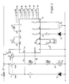
- a control device provided with a display or display field 26 is illustrated at 27 in FIG. 1.
- Inputs of the control unit 27 are via a line 28 to a flow sensor 29 determining the flow temperature (FIG. 2), via a line 30 to a boiler return sensor 31 determining the return temperature, via a line 32 to a boiler sensor 33 monitoring the boiler temperature, via a line 34 to an exhaust gas sensor 35 which determines the exhaust gas temperature, via a line 36 to a room sensor 37 which determines the room temperature and via a line 38 to an external sensor 39 which monitors the outside temperature.
- Outputs of the control device 27 are connected via a line 40 to the supply air blower 13, via a line 41 to the heating pump 21 and via a line 42 to the storage tank charging pump 25.
- a line 43 connects the control unit 27 to a remote or home display 44.
- the control unit 27 is connected to the boiler 10 via a remote ignition or start line 45.
- the heating system including the control device 27 is supplied with power from mains lines L and N (FIG. 2) via a mains switch S1 and a mains input fuse F1. If the mains switch S1 is in the OFF position, a burner which may be connected to an OIL / GAS output is permanently enabled, since this output is connected to a normally closed contact 46. In this way, the burner of a possibly connected oil / gas boiler can be operated. In the OFF position of the power switch S1, the power supply for the control device 27 and all consumers connected to this device are switched off. In the ON position of the power switch S1, the control device 27 is switched on.
- an operating mode selector switch S2 two operating modes, namely manual mode and automatic mode, can be selected.
- the control device 27 processes the measured values of the connected sensors, and it controls the speed of the supply air fan 13 as a function of these measured values. If the selector switch S2 is set to the "manual" position, the supply air fan 13 runs at maximum speed. The burner is constantly blocked.
- a boiler temperature monitor 47 in manual mode which is permanently set to a predetermined boiler temperature and switches off the blower 13 when this temperature is exceeded.
- a safety temperature limiter 48 and a door contact switch 49 in series with the blower motor.
- the fan is always switched off via the safety temperature limiter 48 as soon as a predetermined maximum temperature (e.g. 110 ° C) is exceeded.
- the door contact switch 49 ensures that the fan 13 is switched off automatically when the filling shaft vent or the filling door 12 of the boiler 10 is opened.
- the setpoint of the boiler temperature is expediently determined from the outside temperature and the slope.
- the slope can in turn preferably be set on the control device 27.
- the return sensor 31 is optional, however; if there is no return sensor, the return temperature is disregarded.
- the start process of the boiler control is triggered by actuating a start button 50.
- a predetermined limit value minimum boiler limit
- the supply air blower 13 is made to run at the maximum speed for a period of time determined by a timer. If the minimum boiler temperature is not exceeded during this period, the fan 13 is switched off. If, on the other hand, the minimum boiler limit is exceeded during the start time period predetermined by the timer, normal control mode begins.
- the heating pump 21 is switched on as soon as the boiler temperature exceeds a minimum temperature. If the boiler temperature drops again, pumps 21 and 25 are switched off.
- the fan speed is expediently determined by the deviation between the setpoint and the actual value of the boiler temperature. If the actual value of the boiler temperature is below the target value by at least a predetermined difference, the fan 13 runs at maximum speed. If the actual boiler temperature rises and the deviation between the setpoint and actual value is smaller than the predetermined difference, the fan speed is reduced until the fan 13 is stopped after reaching the setpoint temperature. The speed is only slow, i.e. with high time constant, changed.
- the maximum limitation of the boiler temperature should react in a damped manner, such that the fan speed is throttled from a certain boiler temperature until the fan 13 comes to a standstill at a maximum temperature. If the latter is not possible in individual cases, the maximum limitation must be provided with a hysteresis of a few ° C.
- the exhaust gas temperature preferably also affects the speed of the fan 13. If a specified exhaust gas temperature limit is exceeded, the blower speed is reduced reduced with a time delay. On the other hand, if the exhaust gas temperature falls below a predetermined minimum exhaust gas temperature limit, the fan speed is increased with a time delay.
- the timer mentioned above is started again. If the minimum boiler temperature falls below, the apartment display 44 is expediently put into operation.
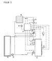
- the feed line 17 and the return line 19 are connected to a motor mixer 51.
- the control device 27 can expediently be designed for weather-dependent flow temperature control and control the mixer 51 to regulate the flow temperature.
- the outside temperature is taken over by the outside sensor 39 which is present anyway.
- the room sensor 37 or a remote control can be connected optionally.
- the controller output line for driving the motor mixer 51 is shown at 52.
- 59 is a flow sensor.
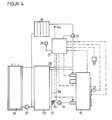
- an additional buffer store 53 is located after the boiler 10, as is known per se from DE-OS 36 24 864.
- a circulation pump 54 and a motor mixer 55 are assigned to the buffer store 53.
- the circulation pump 54 is located in the return line 20.
- the motor mixer 55 is connected to this return line 20 and a connecting line 56 between a lower connecting line 57 and an upper connecting line 58.
- the motor mixer 55 is expediently controlled by the control device 27 as a function of the difference between the boiler temperature and the boiler return temperature.
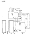
- both the mixer 51 according to FIG. 3 and the mixer 55 according to FIG. 4 are present. Both mixers are advantageously controlled by the control unit 27.
Landscapes
- Engineering & Computer Science (AREA)
- Chemical & Material Sciences (AREA)
- Combustion & Propulsion (AREA)
- Mechanical Engineering (AREA)
- General Engineering & Computer Science (AREA)
- Air Supply (AREA)
Abstract
Vorrichtung zum Regeln der Wärmeleistung eines Festbrennstoffheizkessels durch temperaturabhängige Regelung der von einem Zuluftgebläse dem Kessel zugeführten Zuluftmenge. Das Zuluftgebläse ist an ein Regelgerät angeschlossen, das für eine Änderung der dem Kessel zugeführten Zuluftmenge sorgt. 
Description
Die Erfindung betrifft eine Vorrichtung zum Regeln der Wärmeleistung eines Festbrennstoffheizkessels durch temperaturabhängige Regelung der von einem Zuluftgebläse dem Kessel zugeführten Luftmenge.The invention relates to a device for regulating the heat output of a solid fuel boiler by temperature-dependent regulation of the amount of air supplied to the boiler by a supply air blower.
Bei Vorrichtungen dieser Art ist es bekannt, über einen Regelthermostaten das Zuluftgebläse bei sinkender Kesseltemperatur einzuschalten und bei steigender Kesseltemperatur abzuschalten, um auf diese Weise die Wärmeabgabe des Festbrennstoffheizkessels dem Bedarf anzupassen.In devices of this type, it is known to switch on the supply air blower when the boiler temperature drops and to switch off when the boiler temperature rises, in order to adapt the heat output of the solid fuel boiler to the demand.
Bei einer derartigen Vorrichtung wird durch Ein- bzw. Abschalten des Zuluftgebläses nur die Wärmemenge erzeugt, die für Beheizung, Brauchwasser und dergleichen momentan notwendig ist. Dies führt zu sprunghaften Änderungen in der Leistungsabgabe. Im Teillastbereich der Heizperiode führt dies zu erhöhtem Schadstoffausstoß und zu unkontrollierten Verbrennungsvorgängen.In such a device, only the amount of heat that is currently necessary for heating, process water and the like is generated by switching the supply air blower on or off. This leads to abrupt changes in the power output. In the partial load range of the heating season, this leads to increased pollutant emissions and uncontrolled combustion processes.
Die Anpassung der Leistungsabgabe des Festbrennstoffkessels an die benötigte Leistung, insbesondere der Übergang von Vollast auf Schwachlast, ist jedoch bei Festbrennstoffheizkessen, d.h. Heizkesseln, die insbesondere mit Stückholz beschickt werden, problematisch. Durch Sauerstoffmangel im Kessel kommt es bei zu geringer Wärmeabnahme zu den für Kessel, Kamin und Umwelt schädlichen Sottungsphasen, bei denen ein großer Teil der Energie unnütz verlorengeht. Holz enthält etwa 85% gasende Bestandteile. Das Abschalten des Luftgebläses bei Erreichen der Kesseltemperatur hat bei bekannten Vorrichtungen insbesondere einen steilen Anstieg der Emission von Kohlenmonoxid zur Folge.The adjustment of the output of the solid fuel boiler to the required output, in particular the transition from full load to low load, is however with solid fuel boilers, i.e. Boilers that are particularly loaded with logs are problematic. Due to a lack of oxygen in the boiler, if the heat consumption is too low, the soaking phases are harmful to the boiler, chimney and the environment, during which a large part of the energy is lost. Wood contains about 85% gassing components. Switching off the air blower when the boiler temperature is reached in particular results in a steep increase in the emission of carbon monoxide in known devices.
Der Erfindung liegt die Aufgabe zugrunde, einen Vorrichtung zu schaffen, die es erlaubt, die im Nennlastbetrieb bereits bisher erzielten guten, insbesondere umweltschonenden, Verbrennungswerte auch auf die Schwachlastphase zu übertragen und insbesondere dem in hohem Maße unerwünschten Schadstoffausstoß bei Leistungsminderung zu begegnen.The invention has for its object to provide a device which allows the good, in particular environmentally friendly, combustion values already achieved in the nominal load operation to be transferred to the low-load phase and in particular to counter the highly undesirable pollutant emissions in the event of a reduction in performance.
Diese Aufgabe wird ausgehend von einer Vorrichtung der eingangs genannten Art erfindungsgemäß dadurch gelöst, daß das Zuluftgebläse an ein für eine nur sehr langsame Änderung der dem Kessel zugeführten Zuluftmenge sorgendes Regelgerät angeschlossen ist. Vorzugsweise ist dabei das Regelgerät derart ausgelegt, daß es nach Erreichen einer vorgegebenen Temperatur des Kessels dasThis object is achieved on the basis of a device of the type mentioned at the outset in that the supply air blower is connected to a control device which ensures only a very slow change in the supply air quantity supplied to the boiler. Preferably, the control device is designed such that after reaching a predetermined temperature of the boiler
Zuluftgebläse mit einer hohen Zeitkonstanten langsam auf eine minimale Leistung drosselt und erst dann abschaltet. Die Zeitkonstante kann beispielswiese in der Größenordnung von 5 bis 30 min liegen. Als besonders geeignet erwies sich beispielsweise eine Zeitkonstante von etwa 10 bis 20 min.Supply air fan with a high time constant throttles slowly to a minimum output and only then switches off. The time constant can, for example, be in the order of 5 to 30 minutes. A time constant of approximately 10 to 20 minutes, for example, has proven to be particularly suitable.
Die Vorrichtung nach der Erfindung arbeitet besonders umweltfreundlich, während zugleich ein hoher Wirkungs- und Nutzungsgrad aufrechterhalten wird.The device according to the invention works particularly environmentally friendly, while at the same time maintaining a high degree of efficiency and utilization.
Vorzugsweise bestimmt das vorgesehene Regelgerät die Drehzahl des Zuluftgebläses, obwohl es grundsätzlich auch möglich ist, das Regelgerät auf eine mechanische Luftregeleinrichtung zum Beeinflussen der in den Kessel eingeführten Luftmenge einwirken zu lassen.The control device provided preferably determines the speed of the supply air blower, although it is also possible in principle to let the control device act on a mechanical air control device for influencing the amount of air introduced into the boiler.
Für die Regelung der dem Kessel zugeführten Luftmenge können als Einflußfaktoren zweckmäßig die Kesseltemperatur, die Heizkreisvorlauftemperatur, die Kesselrücklauftemperatur, die Abgastemperatur und die Außentemperatur einzeln, in Kombination oder in beliebigen Teilkombinationen berücksichtigt werden.The boiler temperature, the heating circuit flow temperature, the boiler return temperature, the flue gas temperature and the outside temperature can be taken into account as influencing factors for the control of the air volume supplied to the boiler individually, in combination or in any combination of parts.
In Reihe mit einem dem Antrieb des Zuluftgebläses dienenden Gebläsemotor liegen zweckmäßig ein Sicherheitstemperaturbegrenzer und/oder ein Türkontaktschalter, mittels deren das Gebläse abgeschaltet wird, wenn eine vorbestimmte Höchsttemperatur überschritten bzw. die Füllschachtentgasung bzw. die Kesseltüre geöffnet wird.A safety temperature limiter and / or a door contact switch, by means of which the fan is switched off when a predetermined maximum temperature is exceeded or the filling shaft degassing or the boiler door is opened, are expediently located in series with a fan motor which drives the supply air fan.
An das Regelgerät können zusätzliche Baugruppen angeschlossen sein, insbesondere ein oder mehrere dem Heizkreis zugeordnete Motormischer und/oder ein bzw. mehrere mit dem Heizkreis verbundene zusätzliche Pufferspeicher, die über einen Motormischer logisch be- bzw. entladen werden.Additional modules can be connected to the control device, in particular one or more motor mixers assigned to the heating circuit and / or one or more additional buffer stores connected to the heating circuit, which are logically loaded or unloaded via a motor mixer.
Bevorzugte Ausführungsbeispiele der Erfindung sind nachstehend anhand der beiliegenden Zeichnungen näher erläutert. Es zeigen:
- Fig. 1 schematisch eine Heizanlage mit erfindungsgemäß ausgebildeter Regelvorrichtung,
- Fig. 2 das bei der Anlage nach Fig. 1 verwendete Regelgerät mit daran angeschlossenen Baugruppen, und
- Fign. 3 bis 5 abgewandelte Heizanlagen.
- 1 schematically shows a heating system with a control device designed according to the invention,
- Fig. 2, the control device used in the system of FIG. 1 with modules connected to it, and
- Fig. 3 to 5 modified heating systems.
In Fig. 1 ist ein Festbrennstoffheizkessel insgesamt mit 10 bezeichnet. Der Kessel 10 weist einen Brennstoff-Füllraum 11 auf, in den nach Öffnen einer Fülltür 12 fester Brennstoff, insbesondere Stückholz, eingebracht werden kann. Auf der Fülltür 12 ist ein Zuluftgebläse 13 montiert. Mittels des Gebläses 13 kann in den Brennstoff-Füllraum 11 Zuluft eingeblasen werden. An der der Fülltür 12 gegenüberliegenden Seite des Heizkessels 10 befinden sich ein Heizungsvorlaufanschluß 14, ein Rauchrohr 15 und ein Heizungsrücklaufanschluß 16. Der Vorlaufanschluß 14 steht über eine Leitung 17 mit dem Einlaß eines beliebigen Wärmetauschers 18 in Verbindung, dessen Auslaß über Leitungen 19 und 20 mit dem Rücklaufanschluß 16 verbunden ist. Es versteht sich, daß an Stelle eines Wärmetauschers auch eine Mehrzahl solcher Wärmetauscher vorgesehen sein kann. In der Leitung 17 sitzt eine Heizungs- oder Umwälzpumpe 21. Über Leitungen 22, 23 und die Leitungen 17, 20 steht ferner ein Brauchwasserspeicher 24 mit dem Vorlauf- und dem Rücklaufanschluß 14 bzw. 16 in Verbindung. In der Leitung 23 liegt eine Speicherladepumpe 25.In Fig. 1, a solid fuel boiler is designated by 10 in total. The
Ein mit einem Anzeige- oder Displayfeld 26 versehenes Regelgerät ist in Fig. 1 bei 27 veranschaulicht. Eingänge des Regelgeräts 27 sind über eine Leitung 28 an einen die Vorlauftemperatur bestimmenden Vorlauffühler 29 (Fig. 2), über eine Leitung 30 an einen die Rücklauftemperatur ermittelnden Kesselrücklauffühler 31, über eine Leitung 32 an einen die Kesseltemperatur überwachenden Kesselfühler 33, über eine Leitung 34 an einen die Abgastemperatur bestimmenden Abgasfühler 35, über eine Leitung 36 an einen die Raumtemperatur bestimmenden Raumfühler 37 sowie über eine Leitung 38 an einen die Außentemperatur überwachenden Außenfühler 39 angeschlossen. Ausgänge des Regelgerätes 27 stehen über eine Leitung 40 mit dem Zuluftgebläse 13, über eine Leitung 41 mit der Heizungspumpe 21 und über eine Leitung 42 mit der Speicherladepumpe 25 in Verbindung. Eine Leitung 43 verbindet das Regelgerät 27 mit einer Fern- oder Wohnungsanzeige 44. Schließlich steht das Regelgerät 27 mit dem Kessel 10 über eine Fernzünd- oder Startleitung 45 in Verbindung.A control device provided with a display or
Die Stromversorgung der Heizanlage einschließlich des Regelgerätes 27 erfolgt aus Netzleitungen L und N (Fig. 2) über einen Netzschalter S1 und eine Netzeingangssicherung F1. Befindet sich der Netzschalter S1 in der Stellung AUS, ist ein gegebenenfalls an einem Ausgang BRENNER ÖL/GAS angeschlossener Brenner dauernd freigegeben, da dieser Ausgang an einem Ruhekontakt 46 hängt. Auf diese Weise kann der Brenner eines eventuell angeschlossenen Öl/Gaskessels betrieben werden. In der Stellung AUS des Netzschalters S1 ist die Stromversorgung für das Regelgerät 27 sowie alle an dieses Gerät angeschlossenen Verbraucher abgeschaltet. In der Stellung EIN des Netzschalters S1 ist das Regelgerät 27 eingeschaltet.The heating system including the
Mit Hilfe eines Betriebsarten-Wahlschalters S2 sind zwei Betriebsarten, nämlich Handbetrieb und Automatikbetrieb, wählbar. In der Stellung "Auto" des Betriebsarten-Wahlschalters S2 verarbeitet das Regelgerät 27 die Meßwerte der angeschlossenen Fühler, und es steuert die Drehzahl des Zuluftgebläses 13 in Abhängigkeit von diesen gemessenen Werten. Wird der Wahlschalter S2 in die Stellung "Hand" gebracht, läuft das Zuluftgebläse 13 mit maximaler Drehzahl. Der Brenner ist dauernd blockiert. In Reihe mit dem Gebläsemotor liegt bei Handbetrieb ein Kesseltemperaturwächter 47, der auf eine vorbestimmte Kesseltemperatur fest eingestellt ist und bei Überschreiten dieser Temperatur das Gebläse 13 abschaltet.With the aid of an operating mode selector switch S2, two operating modes, namely manual mode and automatic mode, can be selected. In the "Auto" position of the operating mode selector switch S2, the
Unabhängig von der Schaltstellung des Wahlschalters S2 liegen in Reihe mit dem Gebläsemotor ein Sicherheitstemperaturbegrenzer 48 und ein Türkontaktschalter 49. Über den Sicherheitstemperaturbegrenzer 48 wird das Gebläse in jedem Fall abgeschaltet, sobald eine vorbestimmte Höchsttemperatur (z.B. 110°C) überschritten wird. Der Türkontaktschalter 49 sorgt für ein selbsttätiges Abschalten des Gebläses 13 beim Öffnen der Füllschachtentgasung bzw. der Fülltüre 12 des Kessels 10.Regardless of the switch position of the selector switch S2, there is a safety temperature limiter 48 and a
Der Sollwert der Kesseltemperatur wird zweckmäßig aus der Außentemperatur und der Steilheit bestimmt. Die Steilheit kann ihrerseits vorzugsweise am Regelgerät 27 eingestellt werden. Zusätzlich ist vorteilhafterweise dafür gesorgt, daß sich die Differenz der Kesselvorlauftemperatur und der Kesselrücklauftempera tur auf den Sollwert der Kesseltemperatur auswirkt. Der Rücklauffühler 31 ist jedoch optional; bei nichtvorhandenem Rücklauffühler bleibt die Rücklauftemperatur unberücksichtigt.The setpoint of the boiler temperature is expediently determined from the outside temperature and the slope. The slope can in turn preferably be set on the
Nach Beschicken des Kessels 10 mit festem Brennstoff und dem Anzünden wird der Startvorgang der Kesselregelung durch Betätigung eines Start-Tasters 50 ausgelöst. Unterhalb eines vorgegebenen Grenzwertes (Kesselminimalbegrenzung ) wird das Zuluftgebläse 13 für eine von einem Zeitglied bestimmte Zeitspanne mit der Maximaldrehzahl zum Laufen gebracht. Wird während dieser Zeitspanne die Kesselminimaltemperatur nicht überschritten, wird das Gebläse 13 abgeschaltet. Wird dagegen die Kesselminimalbegrenzung während der von dem Zeitglied vorbestimmten Startzeitspanne überschritten, setzt der normale Regelbetrieb ein. Dabei wird die Heizungspumpe 21 zugeschaltet, sobald die Kesseltemperatur eine Mindesttemperatur überschreitet. Sinkt die Kesseltemperatur wieder ab, werden die Pumpen 21 und 25 abgeschaltet. Im Bereich zwischen der Mindesttemperatur und einer Höchsttemperatur wird die Gebläsedrehzahl zweckmäßig durch die Abweichung zwischen dem Sollwert und dem Istwert der Kesseltemperatur bestimmt. Befindet sich der Istwert der Kesseltemperatur um mindestens einen vorbestimmten Differenzbetrag unter dem Sollwert, läuft das Gebläse 13 auf Maximaldrehzahl. Steigt die Kessel-Isttemperatur an und wird dabei die Abweichung zwischen Soll- und Istwert kleiner als der vorbestimmte Differenzbetrag, wird die Gebläsedrehzahl gesenkt, bis nach Erreichen der Solltemperatur das Gebläse 13 stillgesetzt wird. Dabei wird die Drehzahl nur langsam, d.h. mit hoher Zeitkonstante, geändert.After loading the
Die Kesseltemperatur-Maximalbegrenzung soll gedämpft reagierten, derart, daß ab einer bestimmten Kesseltemperatur die Gebläsedrehzahl gedrosselt wird, bis bei einer maximalen Temperatur der Stillstand des Gebläses 13 eintritt. Sollte letzteres im Einzelfall nicht möglich sein, ist die Maximalbegrenzung mit einer Hysterese von einigen °C zu versehen.The maximum limitation of the boiler temperature should react in a damped manner, such that the fan speed is throttled from a certain boiler temperature until the
Außer den vorstehend genannten Einflußfaktoren wirkt auf die Drehzahl des Gebläses 13 vorzugsweise auch die Abgastemperatur. Wird eine vorgegebene Abgastemperatur-Maximalbegrenzung überschritten, wird die Gebläsedrehzahl zeitlich verzögert reduziert. Wird eine vorbestimmte Abgastemperatur-Minimalbegrenzung dagegen unterschritten, wird die Gebläsedrehzahl zeitlich verzögert angehoben.In addition to the influencing factors mentioned above, the exhaust gas temperature preferably also affects the speed of the
Kommt es nach normalem Heizbetrieb wieder zu einer Unterschreitung der Kesselminimaltemperatur, wird das oben erwähnte Zeitglied erneut gestartet. Bei Unterschreiten der Kesselminimaltemperatur wird zweckmäßig die Wohnungsanzeige 44 in Betrieb gesetzt.If the boiler minimum temperature falls below the normal heating mode again, the timer mentioned above is started again. If the minimum boiler temperature falls below, the
Bei der abgewandelten Ausführungsform gemäß Fig. 3 sind die Vorlaufleitung 17 und die Rücklaufleitung 19 an einen Motormischer 51 angeschlossen. Dabei kann zweckmäßig das Regelgerät 27 für eine witterungsgeführte Vorlauftemperaturregelung ausgelegt sein und den Mischer 51 zur Regelung der Vorlauftemperatur ansteuern. Die Außentemperatur wird von dem ohnehin vorhandenen Außenfühler 39 übernommen. Der Raumfühler 37 oder ein Fernbedienregler können wahlweise angeschlossen werden. Die Reglerausgangsleitung zum Ansteuern des Motormischers 51 ist bei 52 dargestellt. 59 ist ein Vorlauffühler.In the modified embodiment according to FIG. 3, the
Im Falle der in Fig. 4 veranschaulichten abgewandelten Ausführungsform sitzt nach dem Heizkessel 10 ein zusätzlicher Pufferspeicher 53, wie er an sich aus der DE-OS 36 24 864 bekannt ist. Dem Pufferspeicher 53 sind eine Umwälzpumpe 54 und ein Motormischer 55 zugeordnet. Die Umwälzpumpe 54 liegt in der Rücklaufleitung 20. Der Motormischer 55 ist mit dieser Rücklaufleitung 20 und einer Verbindungsleitung 56 zwischen einer unteren Anschlußleitung 57 und einer oberen Anschlußleitung 58 verbunden. Der Motormischer 55 wird zweckmäßig von dem Regelgerät 27 in Abhängigkeit von der Differenz zwischen der Kesseltemperatur und der Kesselrücklauftemperatur angesteuert.In the case of the modified embodiment illustrated in FIG. 4, an
Bei der weiter abgewandelten Ausführungsform gemäß Fig. 5 sind sowohl der Mischer 51 gemäß Fig. 3 als auch der Mischer 55 gemäß Fig. 4 vorhanden. Beide Mischer werden vorteilhaft von dem Regelgerät 27 angesteuert.In the further modified embodiment according to FIG. 5, both the
Claims (10)
Applications Claiming Priority (2)
| Application Number | Priority Date | Filing Date | Title |
|---|---|---|---|
| DE3817598 | 1988-05-24 | ||
| DE3817598A DE3817598A1 (en) | 1988-05-24 | 1988-05-24 | DEVICE FOR CONTROLLING THE COMBUSTION PERFORMANCE OF A SOLID BOILER |
Publications (2)
| Publication Number | Publication Date |
|---|---|
| EP0343660A2 true EP0343660A2 (en) | 1989-11-29 |
| EP0343660A3 EP0343660A3 (en) | 1990-09-26 |
Family
ID=6355003
Family Applications (1)
| Application Number | Title | Priority Date | Filing Date |
|---|---|---|---|
| EP19890109433 Withdrawn EP0343660A3 (en) | 1988-05-24 | 1989-05-24 | Thermal power regulating apparatus for a solid fuel boiler |
Country Status (2)
| Country | Link |
|---|---|
| EP (1) | EP0343660A3 (en) |
| DE (1) | DE3817598A1 (en) |
Cited By (2)
| Publication number | Priority date | Publication date | Assignee | Title |
|---|---|---|---|---|
| EP0624756A1 (en) * | 1993-05-14 | 1994-11-17 | Haiko Paul Künzel | Method for controlling a heating system equipped with solid fuel burner |
| FR2976051A1 (en) * | 2011-05-30 | 2012-12-07 | Electricite De France | Device for driving granulated heater, has output connected to converter and adapted to be connected to heater for sending command for controlling heater based on control commands, and inlet connected to wire for receiving control commands |
Families Citing this family (1)
| Publication number | Priority date | Publication date | Assignee | Title |
|---|---|---|---|---|
| DE4408801C2 (en) * | 1993-03-16 | 2002-10-17 | Ulrich Dreizler | Gas burners |
Family Cites Families (10)
| Publication number | Priority date | Publication date | Assignee | Title |
|---|---|---|---|---|
| US1891100A (en) * | 1929-10-30 | 1932-12-13 | Frank X Lauterbur | Furnace and furnace draft control |
| CH192531A (en) * | 1937-01-14 | 1937-08-31 | Willi Alois | Fire regulation device on central heating boilers for coal firing. |
| US2285226A (en) * | 1941-04-29 | 1942-06-02 | Gen Electric | Fluid flow control |
| DK145685C (en) * | 1976-04-26 | 1983-08-08 | Lars Leksander Slyn Joergensen | METHOD AND APPARATUS FOR REGULATING THE BURNING IN A FIRE |
| LU79664A1 (en) * | 1978-05-16 | 1979-12-06 | M Olieman | METHOD AND DEVICE FOR CONTROLLING BOILER FIRING SYSTEMS |
| DE3025966C2 (en) * | 1980-07-09 | 1983-11-24 | Buderus Ag, 6330 Wetzlar | Automatic control of an induced draft fan and a fresh air flap on boilers for burning solid fuels |
| DE3106015C2 (en) * | 1981-02-18 | 1985-08-01 | "HDG" Entwicklungs- und Patentverwertungsgesellschaft mbH, Wald, Steiermark | Process for operating a heating boiler which can be heated with solid fuel and with oil or gas and device for carrying out the process |
| AT399767B (en) * | 1985-02-07 | 1995-07-25 | Basten Gert | DEVICE FOR ELIMINATING ATMOSPHERIC INFLUENCES ON THE DRAWING BEHAVIOR OF A CHIMNEY |
| KR910002740B1 (en) * | 1986-02-22 | 1991-05-03 | 린나이 가부시기가이샤 | Combustion control device |
| CH673699A5 (en) * | 1986-09-12 | 1990-03-30 | Tiba Kochherd & App Ag | Combustion air regulation system for solid fuel boiler - with separate regulation of total quantity of air and primary secondary air ratio |
-
1988
- 1988-05-24 DE DE3817598A patent/DE3817598A1/en not_active Withdrawn
-
1989
- 1989-05-24 EP EP19890109433 patent/EP0343660A3/en not_active Withdrawn
Cited By (2)
| Publication number | Priority date | Publication date | Assignee | Title |
|---|---|---|---|---|
| EP0624756A1 (en) * | 1993-05-14 | 1994-11-17 | Haiko Paul Künzel | Method for controlling a heating system equipped with solid fuel burner |
| FR2976051A1 (en) * | 2011-05-30 | 2012-12-07 | Electricite De France | Device for driving granulated heater, has output connected to converter and adapted to be connected to heater for sending command for controlling heater based on control commands, and inlet connected to wire for receiving control commands |
Also Published As
| Publication number | Publication date |
|---|---|
| EP0343660A3 (en) | 1990-09-26 |
| DE3817598A1 (en) | 1989-11-30 |
Similar Documents
| Publication | Publication Date | Title |
|---|---|---|
| EP0614046A1 (en) | Control device for gas burner automats of heating installations | |
| DE3700084C2 (en) | ||
| EP0484280B1 (en) | A plant for the purification of pollutant containing air | |
| EP2210044B1 (en) | Method for regulating a solid fuel firing unit | |
| DE4316182A1 (en) | Method for controlling and / or regulating a heating system equipped with a solid fuel boiler and device for carrying out the method | |
| EP0614047B1 (en) | Electronic control device for gas burners of heating installations | |
| EP0343660A2 (en) | Thermal power regulating apparatus for a solid fuel boiler | |
| DE4408801C2 (en) | Gas burners | |
| DE3517902C2 (en) | ||
| DE2910294C2 (en) | Temperature controller | |
| EP0556736A1 (en) | Method of controlling a boiler | |
| EP2275748A2 (en) | Method for operating a heating assembly and heating assembly | |
| DE3538934C2 (en) | ||
| DE19601517A1 (en) | Regulator for gas heater with burner and gas valve | |
| EP0544622A1 (en) | Dual fuel boiler installation for a central heating with an oil- and a wood-fired boiler | |
| DE2918360A1 (en) | Regulated system for boiler combustion plant - has fan mixing fuel gas and air to heat output demand | |
| DE68914121T2 (en) | Automatic control method and device for a solid fuel boiler with interrupted loading and forced draft, especially for wood boilers. | |
| EP0151460A2 (en) | Space-heating system | |
| AT412504B (en) | METHOD FOR LOADING A STORAGE OF A HEATING SYSTEM | |
| EP4204735B1 (en) | Electronic closed-loop control device for fireplaces comprising a lower combustion system | |
| AT397854B (en) | Method for controlling a boiler | |
| AT403414B (en) | Method for controlling the boiler return temperature | |
| DE3731318C2 (en) | ||
| DE4413186B4 (en) | Procedure for boiler return temperature control | |
| DE4339016B4 (en) | Method for operating a power supply |
Legal Events
| Date | Code | Title | Description |
|---|---|---|---|
| PUAI | Public reference made under article 153(3) epc to a published international application that has entered the european phase |
Free format text: ORIGINAL CODE: 0009012 |
|
| AK | Designated contracting states |
Kind code of ref document: A2 Designated state(s): AT BE CH DE ES FR GB GR IT LI LU NL SE |
|
| PUAL | Search report despatched |
Free format text: ORIGINAL CODE: 0009013 |
|
| AK | Designated contracting states |
Kind code of ref document: A3 Designated state(s): AT BE CH DE ES FR GB GR IT LI LU NL SE |
|
| 17P | Request for examination filed |
Effective date: 19901231 |
|
| 17Q | First examination report despatched |
Effective date: 19920625 |
|
| STAA | Information on the status of an ep patent application or granted ep patent |
Free format text: STATUS: THE APPLICATION IS DEEMED TO BE WITHDRAWN |
|
| 18D | Application deemed to be withdrawn |
Effective date: 19930928 |