EP0343531B1 - Evaporateur avec un dispositif pour contrôler le flux de particules solides - Google Patents
Evaporateur avec un dispositif pour contrôler le flux de particules solides Download PDFInfo
- Publication number
- EP0343531B1 EP0343531B1 EP89109063A EP89109063A EP0343531B1 EP 0343531 B1 EP0343531 B1 EP 0343531B1 EP 89109063 A EP89109063 A EP 89109063A EP 89109063 A EP89109063 A EP 89109063A EP 0343531 B1 EP0343531 B1 EP 0343531B1
- Authority
- EP
- European Patent Office
- Prior art keywords
- evaporator
- solid particles
- chamber
- heat exchange
- exchange tubes
- Prior art date
- Legal status (The legal status is an assumption and is not a legal conclusion. Google has not performed a legal analysis and makes no representation as to the accuracy of the status listed.)
- Expired - Lifetime
Links
- 239000002245 particle Substances 0.000 title claims abstract description 70
- 239000007787 solid Substances 0.000 title claims abstract description 69
- 238000000926 separation method Methods 0.000 claims abstract description 52
- 239000007788 liquid Substances 0.000 claims abstract description 33
- 239000002002 slurry Substances 0.000 claims description 40
- 230000003134 recirculating effect Effects 0.000 claims description 5
- 230000005484 gravity Effects 0.000 claims description 2
- 239000000243 solution Substances 0.000 description 37
- 238000000034 method Methods 0.000 description 14
- 229910000831 Steel Inorganic materials 0.000 description 4
- 238000004140 cleaning Methods 0.000 description 4
- 239000012530 fluid Substances 0.000 description 4
- 238000004519 manufacturing process Methods 0.000 description 4
- 239000010959 steel Substances 0.000 description 4
- 230000005465 channeling Effects 0.000 description 3
- 239000011552 falling film Substances 0.000 description 3
- 239000000463 material Substances 0.000 description 3
- 238000007670 refining Methods 0.000 description 2
- 239000002904 solvent Substances 0.000 description 2
- 238000011144 upstream manufacturing Methods 0.000 description 2
- 230000015572 biosynthetic process Effects 0.000 description 1
- 239000012267 brine Substances 0.000 description 1
- 238000004891 communication Methods 0.000 description 1
- 238000010276 construction Methods 0.000 description 1
- 230000001419 dependent effect Effects 0.000 description 1
- 238000013461 design Methods 0.000 description 1
- 238000011161 development Methods 0.000 description 1
- 230000018109 developmental process Effects 0.000 description 1
- 230000002708 enhancing effect Effects 0.000 description 1
- 238000001704 evaporation Methods 0.000 description 1
- 230000008020 evaporation Effects 0.000 description 1
- 239000010408 film Substances 0.000 description 1
- 238000001914 filtration Methods 0.000 description 1
- 239000000446 fuel Substances 0.000 description 1
- 238000010438 heat treatment Methods 0.000 description 1
- 230000002363 herbicidal effect Effects 0.000 description 1
- 239000004009 herbicide Substances 0.000 description 1
- -1 i.e. Substances 0.000 description 1
- 238000012423 maintenance Methods 0.000 description 1
- 239000002184 metal Substances 0.000 description 1
- 239000003960 organic solvent Substances 0.000 description 1
- 230000000737 periodic effect Effects 0.000 description 1
- 239000000575 pesticide Substances 0.000 description 1
- 239000002244 precipitate Substances 0.000 description 1
- 238000012545 processing Methods 0.000 description 1
- 150000003839 salts Chemical class 0.000 description 1
- HPALAKNZSZLMCH-UHFFFAOYSA-M sodium;chloride;hydrate Chemical compound O.[Na+].[Cl-] HPALAKNZSZLMCH-UHFFFAOYSA-M 0.000 description 1
- 239000010409 thin film Substances 0.000 description 1
- 238000005406 washing Methods 0.000 description 1
- XLYOFNOQVPJJNP-UHFFFAOYSA-N water Substances O XLYOFNOQVPJJNP-UHFFFAOYSA-N 0.000 description 1
Images
Classifications
-
- B—PERFORMING OPERATIONS; TRANSPORTING
- B01—PHYSICAL OR CHEMICAL PROCESSES OR APPARATUS IN GENERAL
- B01D—SEPARATION
- B01D1/00—Evaporating
- B01D1/06—Evaporators with vertical tubes
- B01D1/12—Evaporators with vertical tubes and forced circulation
-
- C—CHEMISTRY; METALLURGY
- C02—TREATMENT OF WATER, WASTE WATER, SEWAGE, OR SLUDGE
- C02F—TREATMENT OF WATER, WASTE WATER, SEWAGE, OR SLUDGE
- C02F1/00—Treatment of water, waste water, or sewage
- C02F1/02—Treatment of water, waste water, or sewage by heating
- C02F1/04—Treatment of water, waste water, or sewage by heating by distillation or evaporation
- C02F1/042—Prevention of deposits
-
- C—CHEMISTRY; METALLURGY
- C02—TREATMENT OF WATER, WASTE WATER, SEWAGE, OR SLUDGE
- C02F—TREATMENT OF WATER, WASTE WATER, SEWAGE, OR SLUDGE
- C02F1/00—Treatment of water, waste water, or sewage
- C02F1/02—Treatment of water, waste water, or sewage by heating
- C02F1/04—Treatment of water, waste water, or sewage by heating by distillation or evaporation
- C02F1/048—Purification of waste water by evaporation
-
- F—MECHANICAL ENGINEERING; LIGHTING; HEATING; WEAPONS; BLASTING
- F28—HEAT EXCHANGE IN GENERAL
- F28F—DETAILS OF HEAT-EXCHANGE AND HEAT-TRANSFER APPARATUS, OF GENERAL APPLICATION
- F28F19/00—Preventing the formation of deposits or corrosion, e.g. by using filters or scrapers
- F28F19/01—Preventing the formation of deposits or corrosion, e.g. by using filters or scrapers by using means for separating solid materials from heat-exchange fluids, e.g. filters
-
- Y—GENERAL TAGGING OF NEW TECHNOLOGICAL DEVELOPMENTS; GENERAL TAGGING OF CROSS-SECTIONAL TECHNOLOGIES SPANNING OVER SEVERAL SECTIONS OF THE IPC; TECHNICAL SUBJECTS COVERED BY FORMER USPC CROSS-REFERENCE ART COLLECTIONS [XRACs] AND DIGESTS
- Y10—TECHNICAL SUBJECTS COVERED BY FORMER USPC
- Y10S—TECHNICAL SUBJECTS COVERED BY FORMER USPC CROSS-REFERENCE ART COLLECTIONS [XRACs] AND DIGESTS
- Y10S159/00—Concentrating evaporators
- Y10S159/901—Promoting circulation
Definitions
- the present invention relates to an evaporator for concentrating slurries and solutions containing solid particles and liquid of the type as disclosed in the preamble of claim 1.
- the invention further relates to a method for concentrating slurries or solutions containing solid particles and liquid of the type as described in the preamble of claim 7.
- evaporators for concentrating solutions and slurries, including oil refining, synthetic fuel production, food processing, herbicide and pesticide production, electric generating stations, primary metal refining, pharmaceutical production, and pulp and paper manufacture.
- the evaporators may be used to increase the concentration of a fluid component, and/or to crystallize a solute component.
- Various types of evaporators are available and are well known in the prior art.
- evaporators are the vertical, tube-in-shell, falling film evaporators of the above-mentioned publications.
- a solution or slurry is circulated repeatedly through heat exchange tubes.
- the solvent i.e., water or organic solvent, is gradually evaporated, leaving a more concentrated solution or slurry, and often causing solute components to precipitate.
- Evaporators typically include various chambers, apertures, and tubes through which the solution or slurry must pass repeatedly as it is concentrated. Care must be taken to provide for efficient flow of solid particles as well as liquid. Slurries contain solid particles even during initial stages of concentration, while solutions contain solutes, i.e., salts which may precipitate out of solution during concentration. These solid particles can cause clogging in various parts of the evaporator.
- Deposits may occur along the walls or other surfaces of the evaporator. Deposits may break off in the form of chips or flakes, which can cause clogging of the evaporator and interrupt the flow of the solution or slurry to be concentrated. If the system is clogged and circulation cannot proceed efficiently, the system must be shut down to allow operators to clear and clean the blockage.
- Deposits occur while the evaporator is in operation and also while the evaporator is shut down for cleaning; as the walls of the evaporator system are allowed to dry out during the cleaning operation, significant amounts of deposits can form. When the system is restarted and circulation is restored, the new deposits often flake off and reclog the system.
- the present invention fulfills the above-mentioned need by providing the evaporator of claim 1 and the method of claim 7.
- the present invention discloses an evaporator for concentrating slurries or solutions containing solid particles and liquid.
- evaporators may be falling film evaporators, and the like. They include a plurality of substantially vertical heat exchange tubes, a lower reservoir positioned below the heat exchange tubes, a second reservoir positioned above the heat exchange tubes, and recirculation conduit for recirculating slurry or solution from the lower reservoir to the upper reservoir.
- the evaporator includes a solid particle flow apparatus having a separation chamber which has an inlet and an outlet. The inlet is positionable to receive slurry or solution from the recirculation conduit. The outlet is connected to the bypass conduit, described below. The outlet may be positioned at substantially the lowest portion of the separation chamber to encourage travel of the separated solid particles toward the outlet under the influence of gravity.
- the separation chamber also has a plurality of apertures which are sized to separate solid particles from liquid.
- the size of each aperture is a "critical" size - a predetermined size above which the solid particles cause unacceptable clogging of various parts of the evaporator. Solid particles larger than the critical size are preferably separated from the liquid to prevent clogging downstream.
- the chamber apertures communicate a substantial portion of the liquid to the upper reservoir exterior of the separation chamber for passage through the heat exchange tubes to the lower reservoir.
- the solid particle flow apparatus has a bypass conduit which is connected to the outlet of the separation chamber and which is positionable to channel solid particles which are larger than the critical size from the separation chamber to the lower reservoir.
- the solid particles which are channeled through the bypass conduit do not enter the upper reservoir exterior of the separation chamber.
- a substantial portion of the liquid exits the separation chamber through the apertures to the upper reservoir exterior of the separation chamber. The liquid is then recombined with the separated solid particles in the lower reservoir after fist passing through the heat exchange tubes.
- the bypass conduit may be positionable to channel the separated solid particles to one or more of the plurality of heat exchange tubes for travel to the lower reservoir while preventing the separated solid particles from entering the remainder of the plurality of heat exchange tubes.
- the separation chamber or a portion thereof, may be substantially conical in shape.
- the separation chamber may be constructed from steel screen material, or from steel material in which apertures have been punched or formed.
- the separation chamber may be sized to fit between an upper wall of the evaporator and the top of the heat exchange tubes. Further, the separation chamber may be attached for support to an upper wall of the evaporator.
- the chamber inlet may be positioned in an upper portion of the separation.
- the chamber outlet may be positioned in a lower portion of of the chamber.
- the chamber may be conical in shape and may have an outlet in a lower portion of the conically-shaped chamber.
- the chamber may also have tapered sidewalls and may have an outlet positioned at a lower point of the tapered sidewalls.
- the present invention also includes a method for selectively and continuously separating solid particles having a size larger than a critical size from liquid in a slurry or solution being concentrated in an evaporator.
- the critical size is a predetermined size above which the solid particles cause unacceptable clogging in various apertures in the evaporator.
- the method includes the steps of providing at least a first reservoir for the slurry or solution; separating from the liquid solid particles having a size larger than a critical size; channeling to the first reservoir the solid particles which were removed from the liquid; and channeling the concentrated liquid to the first reservoir.
- the separation step may also include the steps of providing a separation chamber having apertures with a size substantially equal to the critical size or smaller; providing a second reservoir in fluid communication with the heat exchanger; positioning the separation chamber within the second reservoir; and recirculating the slurry or solution from the first reservoir into the separation chamber.
- the step of channeling the solid particles to the first reservoir may further include the step of providing a bypass conduit connected to and leading from the separation chamber to the first reservoir without passage of the separated solid particles through the heat exchanger.
- the solid particle flow apparatus is designed for use with an evaporator for concentrating slurries and/or solutions.
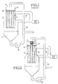
- a typical prior art falling film evaporator is shown in Figure 1.
- Such evaporators usually include a plurality of heat exchange tubes 10 arranged substantially vertically.
- the evaporator also has an upper reservoir or flood box 12, a lower reservoir or sump 14, and a recirculation means 16 for recirculating the slurry or solution from the lower reservoir to the upper reservoir.
- the recirculation means typically includes at least one recirculation conduit 20, and a recirculation pump 18.
- heating means typically present in evaporators, but not shown for clarity, are heating means, means for introducing slurry or solution to the evaporator, and means for removing concentrated slurry or solution from the evaporator.
- an evaporator such as the one depicted in Figure 1 continuously circulates the slurry or solution from the lower reservoir 14, through the recirculating means 16, back to the upper reservoir 12.
- the slurry or solution repeatedly passes through the heat exchange tubes 10, where solvent is evaporated, leaving a more concentrated slurry or solution.
- the heat exchange tubes 10 may be fitted with distributors 22 which direct the slurry or solution as it enters the heat exchange tubes.
- distributors An example of distributors is described in United States patent number 4,248,296, issued to Louis J. Jezek and entitled "Fluid Distributor for Condensor Tubes".
- Distributors such as those described in the Jezek patent, introduce the slurry or solution into the heat exchange tubes in a film form, thus enhancing evaporation.
- Such distributors have small apertures which must remain open in order for the evaporator to run most efficiently. Solid particles, such as chips or flakes in the slurry or solution can block and clog the apertures in the distributor, preventing normal thin film flow and limiting performance of the heat exchange tubes, or if completely blocked, effectively remove the tube from service.
- the solid particle flow apparatus is designed to prevent such blockage, in distributors or elsewhere in the system, by selectively controlling the flow of solid particles.
- Figure 2 shows the evaporator of Figure 1 fitted with this apparatus.
- the solid particle flow apparatus includes a separation chamber 24 and a bypass conduit 26.
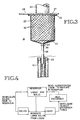
- FIG. 3 is a more detailed illustration of the solid particle flow apparatus.
- the separation chamber 24 is fitted within the upper reservoir 12 and is positioned below an outlet 27 of the recirculation conduit 20.
- the separation chamber is preferably attached to a cover 28 of the upper reservoir by bolts, screws, pins or other means of attachment 30.
- the separation chamber 24 includes a plurality of apertures 32 which are sized to separate solid particles from liquid.
- Each chamber aperture 32 is of a "critical size.”
- the critical size may vary from system to system but should be equal to or smaller than the apertures downstream of the separation chamber and upstream of the heat exchange tubes.
- the chamber apertures 32 should be of such dimensions as to separate from the liquid all solid particles which are large enough to block apertures downstream of the separation chamber and upstream of the heat exchange tubes, for example, the apertures in the distributors 22.
- the separation chamber 24 may be constructed from sheet steel into which holes, preferably round ones, have been punched or otherwise formed. It also may be constructed from steel screen or mesh material.
- the separation chamber is conical in shape, or at least a lower portion 33 of the separation chamber is conical in shape, such as is shown in Figure 3. This shape helps to funnel the solid particles down to an outlet 34 of the separation chamber 24 which is located at the bottom of the lower portion 33 of the separation chamber.
- the chamber outlet communicates with the bypass conduit 26.
- the bypass conduit is attached to the chamber outlet 34 by conventional attachment means 36.
- the bypass conduit extends from the separation chamber outlet into at least one of the heat exchange tubes 10.
- the bypass conduit is sized to fit within the heat exchange tube.
- the heat exchange tube into which the bypass conduit is fitted has no distributor in it.
- the apparatus may be incorporated into evaporators during original construction, or, may be retrofitted to existing evaporators.
- many evaporators have doors, or manholes, in the top of the upper reservoir 12 to allow operators to enter the upper reservoir to permit its cleaning and maintenance.
- the apparatus may be constructed outside the evaporator and then installed by an operator entering the upper reservoir through the existing doors. Not only does the apparatus improve the efficiency of the conventional evaporator, the apparatus is economical to construct and install as original equipment or as a retrofit on existing evaporators.
- the slurry or solution circulating in the evaporator undergoes concentration. It is circulated from the lower reservoir 14 to the upper reservoir 12 through the recirculation conduit 20.
- the separation chamber 24 receives the recirculated slurry or solution from the outlet 27 of the recirculation conduit.
- the slurry or solution undergoes physical separation, whereby solid particles which are larger than the critical size are separated from the liquid, and a substantial portion of the liquid component exits the separation chamber through the chamber apertures 32.
- the exiting liquid enters the upper reservoir exterior of the separation chamber and then enters the heat exchange tubes 10 where it is further concentrated. Solid particles which are larger than the critical size and will not pass through the chamber apertures 32 exit the separation chamber through the chamber outlet 34 into the bypass conduit 26. The solid particles then pass directly to one of the heat exchange tubes 10 into which the bypass conduit is fitted for travel to the lower reservoir 14.
- the separation chamber 24 also helps to reduce the size of the solid particles through turbulence and impact of the solid particles against the wall of the separation chamber. When the size of the solid particles is sufficiently reduced, the solid particles will no longer cause clogging problems in the evaporator.
- the present invention also includes a method for selectively controlling the flow of solid particles within the evaporator.
- the following discussion of the method of the present invention is better understood with reference to the flow chart shown in Figure 4.
- a slurry or solution undergoing concentration in the evaporator is held in the reservoir.
- the slurry or solution has a liquid component and solid particles, the solid particles usually being of varying sizes.
- the first step of the method of the present invention is to separate from the liquid component the solid particles which are larger than the critical size. Particles which are larger than the critical size and which, therefore, will not flow through downstream apertures will be removed from the slurry or solution before the slurry or solution continues downstream, i.e., enters the distributors of the evaporator.
- a second step in the method is to recirculate the separated solid particles back to the reservoir containing the slurry or solution.
- this step of recirculation is achieved by washing the solid particles through a conduit with the aid of some of the liquid from the slurry or solution.
- a third step in the method is to direct the separated liquid to the heat exchange tubes to the evaporator.
- the liquid may contain solid particles; however, they will all be of a size smaller than the critical size and hence will not create blockage problems in the distributors or heat exchange tubes. Within the heat exchange tubes, the liquid undergoes concentration.
- a final step in the method is to direct the concentrated liquid back to the reservoir containing the slurry or solution where it is again mixed with the solids which were removed in the first step.
- the method of the present invention provides for continual circulation of solid particles, and does not provide for a building up of solid particles at any point in the system, such as would a conventional filter.
- the solid particles are constantly separated from the liquid and recirculated, at least a portion of them will decrease in size as a result of the turbulence, and will pose less of a clogging problem.
Landscapes
- Engineering & Computer Science (AREA)
- Chemical & Material Sciences (AREA)
- Life Sciences & Earth Sciences (AREA)
- Organic Chemistry (AREA)
- Water Supply & Treatment (AREA)
- Environmental & Geological Engineering (AREA)
- Hydrology & Water Resources (AREA)
- Mechanical Engineering (AREA)
- Chemical Kinetics & Catalysis (AREA)
- General Engineering & Computer Science (AREA)
- Physics & Mathematics (AREA)
- Thermal Sciences (AREA)
- Vaporization, Distillation, Condensation, Sublimation, And Cold Traps (AREA)
- Physical Or Chemical Processes And Apparatus (AREA)
Claims (7)
- Evaporateur de concentration de bouillies et de solutions contenant des particules solides et un liquide, comprenant de multiples tubes d'échange de chaleur généralement verticaux (10), un réservoir inférieur (14) placé sous les tubes d'échange de chaleur (10), un réservoir supérieur (12) placé au-dessus des tubes d'échange de chaleur (10), et un conduit de recyclage (20) pour recycler la bouillie ou la solution du réservoir inférieur (14) vers le réservoir supérieur (12), caractérisé par un appareillage (24, 26) de commande sélective de la circulation des particules solides ayant une dimension plus grande qu'une dimension critique, la dimension critique étant une dimension prédéterminée au-dessus de la laquelle les particules solides provoquent un colmatage inadmissible de l'évaporateur, comprenant :
un moyen d'évacuation (24) pour évacuer de la bouillie ou de la solution des particules solides ayant une dimension plus grande que la dimension critique ; ledit moyen d'évacuation (24) faisant communiquer une partie importante du liquide avec le réservoir supérieur (12) à l'extérieur dudit moyen d'évacuation (24) pour le faire passer par les tubes d'échange de chaleur (10) vers le réservoir inférieur (14) ; et
un moyen de dérivation (26) raccordé audit moyen d'évacuation (24) et pouvant être placé de manière à canaliser à la sortie dudit moyen d'évacuation (24) les particules solides qui sont plus grandes que la dimension critique pour les diriger vers le réservoir inférieur (14) sans qu'elles entrent dans le réservoir supérieur (12) à l'extérieur dudit moyen d'évacuation (24). - Evaporateur selon la revendication 1, dans lequel ledit moyen d'évacuation comporte une chambre présentant des trous (32) ayant une dimension sensiblement égale à la dimension critique ou plus petite.
- Evaporateur selon la revendication 2, dans lequel ladite chambre comporte une entrée et une sortie (34) et peut être placée à l'intérieur du réservoir supérieur, et dans lequel l'entrée de la chambre est placée pour recevoir de la bouillie ou de la solution du conduit de recyclage (20).
- Evaporateur selon la revendication 3, dans lequel ladite sortie (34) de la chambre est placée sensiblement à la partie la plus basse de ladite chambre de séparation (24) pour faciliter le déplacement des particules solides séparées vers ladite sortie (34) de la chambre sous l'influence de la gravité.
- Evaporateur selon l'une quelconque des revendications 1 à 4, dans lequel ledit moyen de dérivation (26) comprend un conduit pouvant être placé de manière à faire circuler les particules solides séparées par un ou plusieurs des multiples tubes d'échange de chaleur (10) pour les diriger vers le réservoir inférieur (14) tout en empêchant les particules solides séparées d'entrer dans le reste des multiples tubes d'échange de chaleur (10).
- Evaporateur selon l'une quelconque des revendications 2 à 5, dans lequel ladite chambre de séparation (24) est dimensionnée de manière qu'elle se loge entre une paroi supérieure de l'évaporateur et les tubes d'échange de chaleur (10), ladite chambre de séparation (24) étant fixée de manière qu'elle soit supportée par une paroi supérieure (28) de l'évaporateur.
- Procédé de concentration de bouillies et de solutions contenant des particules solides et un liquide dans un évaporateur dans lequel la bouillie ou la solution circule d'un échangeur de chaleur (10) à un premier réservoir (14), caractérisé en ce que pour commander sélectivement et continuellement la circulation de particules solides ayant une dimension plus grande qu'une dimension critique, la dimension critique étant une dimension prédéterminée au-dessus de laquelle les particules solides provoquent un colmatage inadmissible de l'évaporateur, des particules solides ayant une dimension plus grande que la dimension critique sont séparées du liquide et canalisées vers le premier réservoir (14), le liquide duquel les particules solides ont été évacuées est canalisé vers l'échangeur de chaleur (10) pour une concentration du liquide, et le liquide concentré est canalisé vers le premier réservoir (14) pour le recombiner avec les particules solides séparées.
Applications Claiming Priority (2)
| Application Number | Priority Date | Filing Date | Title |
|---|---|---|---|
| US198325 | 1980-10-20 | ||
| US07/198,325 US5000821A (en) | 1988-05-25 | 1988-05-25 | Apparatus for controlling solid particle flow in an evaporator |
Publications (2)
| Publication Number | Publication Date |
|---|---|
| EP0343531A1 EP0343531A1 (fr) | 1989-11-29 |
| EP0343531B1 true EP0343531B1 (fr) | 1994-08-03 |
Family
ID=22732911
Family Applications (1)
| Application Number | Title | Priority Date | Filing Date |
|---|---|---|---|
| EP89109063A Expired - Lifetime EP0343531B1 (fr) | 1988-05-25 | 1989-05-19 | Evaporateur avec un dispositif pour contrôler le flux de particules solides |
Country Status (7)
| Country | Link |
|---|---|
| US (1) | US5000821A (fr) |
| EP (1) | EP0343531B1 (fr) |
| JP (1) | JP2685578B2 (fr) |
| AT (1) | ATE109555T1 (fr) |
| AU (1) | AU610976B2 (fr) |
| CA (1) | CA1316098C (fr) |
| DE (1) | DE68917207T2 (fr) |
Families Citing this family (10)
| Publication number | Priority date | Publication date | Assignee | Title |
|---|---|---|---|---|
| US5000821A (en) * | 1988-05-25 | 1991-03-19 | Resources Conservation Company | Apparatus for controlling solid particle flow in an evaporator |
| SE9303762L (sv) * | 1993-11-15 | 1995-05-16 | Eka Nobel Ab | Sätt att rena processvatten från massaframställning |
| SE9502198L (sv) * | 1995-06-16 | 1996-12-17 | Eka Chemicals Ab | Upplösning av inkruster vid indunstning av surt och alkaliskt avloppsvatten |
| FR2751736B1 (fr) * | 1996-07-29 | 1999-01-15 | Tami Ind | Dispositif pour fragmenter des elements heterogenes d'un milieu fluide destine a circuler a l'interieur d'un appareil echangeur et installation en faisant application |
| FR2763118B1 (fr) | 1997-05-09 | 1999-08-06 | Packinox Sa | Dispositif d'injection de fluides sous pression dans un echangeur thermique a plaques et procede de nettoyage d'un tel dispositif d'injection |
| DE60007811T2 (de) * | 1999-08-23 | 2004-11-25 | Nippon Shokubai Co., Ltd. | Verfahren zur Verhinderung von Verstopfungen in einem Plattenwärmetauscher |
| US7312101B2 (en) * | 2003-04-22 | 2007-12-25 | Micron Technology, Inc. | Packaged microelectronic devices and methods for packaging microelectronic devices |
| DE102012011290A1 (de) * | 2012-06-08 | 2013-12-12 | Bma Braunschweigische Maschinenbauanstalt Ag | Fallstromverdampfer |
| CN109350977A (zh) * | 2018-11-02 | 2019-02-19 | 清华大学 | 蒸汽减压装置及工作方法 |
| WO2020123050A1 (fr) * | 2018-12-13 | 2020-06-18 | Applied Materials, Inc. | Échangeur de chaleur à refroidissement à plusieurs étages |
Citations (3)
| Publication number | Priority date | Publication date | Assignee | Title |
|---|---|---|---|---|
| DE2254677B1 (de) * | 1972-11-08 | 1974-05-30 | Ludwig Taprogge Reinigungsanlagen Fuer Roehren-Waermeaustauscher, 4034 Angermund | Einrichtung zum Aussortieren von im Kühlwasserkreislauf eines Kondensators mitgefühlten abgeriebenen Reinigungskugel |
| DE3125503A1 (de) * | 1980-06-30 | 1982-03-25 | Hitachi, Ltd., Tokyo | Sortiervorrichtung |
| JPS5840497A (ja) * | 1981-09-04 | 1983-03-09 | Hitachi Ltd | 洗浄体選別器 |
Family Cites Families (37)
| Publication number | Priority date | Publication date | Assignee | Title |
|---|---|---|---|---|
| US548986A (en) * | 1895-10-29 | hewitt | ||
| US521974A (en) * | 1894-06-26 | Cooper | ||
| US351795A (en) * | 1886-11-02 | Vacuum evaporating apparatus | ||
| US470060A (en) * | 1892-03-01 | The norbis feters co | ||
| US774201A (en) * | 1902-10-06 | 1904-11-08 | Herbert Robischon | Catch-basin for sink-outlets. |
| US898147A (en) * | 1906-08-21 | 1908-09-08 | Erich Von Seemen | Evaporator. |
| US1028737A (en) * | 1911-08-22 | 1912-06-04 | Kestner Evaporator Company | Process of evaporation and apparatus therefor. |
| US1191108A (en) * | 1915-05-13 | 1916-07-11 | Kestner Evaporator Company | Evaporator. |
| US2182428A (en) * | 1935-11-11 | 1939-12-05 | Fladmark Erling | Method of recovering the solids from pulp mill waste liquors |
| US2199320A (en) * | 1936-09-30 | 1940-04-30 | Juge Sergius Von Le | Evaporator for production of high-grade distillate |
| US2512938A (en) * | 1945-07-20 | 1950-06-27 | Roy O Henszey | Evaporator and separator |
| US2583364A (en) * | 1949-07-01 | 1952-01-22 | Blaw Knox Co | Apparatus for supplying and distributing liquids |
| US2764233A (en) * | 1950-07-27 | 1956-09-25 | Minute Maid Corp | Apparatus for concentrating citrus juices or the like |
| US2800307A (en) * | 1954-06-04 | 1957-07-23 | Stratford Eng Corp | Apparatus for controlling temperature change of blends of fluids or fluids and finely divided solids |
| US2993884A (en) * | 1958-02-06 | 1961-07-25 | Ciba Ltd | Metal complexes of monoazo-dyestuffs |
| US3056831A (en) * | 1958-04-25 | 1962-10-02 | Stratford Eng Corp | Sulfur trioxide sulfonation method |
| US3192130A (en) * | 1960-02-08 | 1965-06-29 | Jr John E Pottharst | Forced circulation evaporator |
| US2998060A (en) * | 1960-08-03 | 1961-08-29 | Albert W Eckstrom | High temperature method and evaporator for concentrating solutions |
| US3177129A (en) * | 1961-07-03 | 1965-04-06 | Halcon International Inc | Distillation column and reboiler |
| US3292999A (en) * | 1963-04-29 | 1966-12-20 | Chicago Bridge & Iron Co | Crystallizer with baffled recirculation flow |
| SE303303B (fr) * | 1965-07-12 | 1968-08-26 | Alfa Laval Ab | |
| CH466221A (de) * | 1968-01-16 | 1968-12-15 | Sulzer Ag | Fallstromverdampfer, insbesondere für Rektifizierkolonnen |
| DE1692967B2 (de) * | 1968-03-15 | 1977-03-24 | Maschinenfabrik Buckau R. Wolf Ag, 4048 Grevenbroich | Fallstromverdampfer fuer die zuckerindustrie |
| DE2212816C3 (de) * | 1972-03-16 | 1974-12-12 | Wiegand Karlsruhe Gmbh, 7505 Ettlingen | Vorrichtung zur gleichmäßigen Verteilung einzudampfender Flüssigkeit in einem Fallstromverdampfer |
| US3819053A (en) * | 1972-10-02 | 1974-06-25 | Gen Electric | Waste treatment system |
| US3933576A (en) * | 1973-05-17 | 1976-01-20 | Whiting Corporation | Evaporation of radioactive wastes |
| US3880702A (en) * | 1973-06-29 | 1975-04-29 | Boris Alexandrovich Troshenkin | Film type evaporator |
| CA1013665A (en) * | 1974-01-02 | 1977-07-12 | Hooker Chemicals And Plastics Corp. | Evaporation apparatus |
| US3976430A (en) * | 1974-08-05 | 1976-08-24 | Hooker Chemicals & Plastics Corporation | Forced circulation cooling crystallizer |
| DE2725119C2 (de) * | 1977-06-03 | 1979-06-28 | Ulrich Dr.-Ing. 5100 Aachen Regehr | Separatorvorrichtung für Eindampfanlagen |
| US4248296A (en) * | 1979-08-07 | 1981-02-03 | Resources Conservation Company | Fluid distributor for condenser tubes |
| US4288285A (en) * | 1980-07-28 | 1981-09-08 | Evaporator Technology Corporation | Apparatus for forming a vortex |
| US4734269A (en) * | 1985-06-11 | 1988-03-29 | American Hospital Supply Corporation | Venous reservoir bag with integral high-efficiency bubble removal system |
| US4683025A (en) * | 1986-02-10 | 1987-07-28 | The Graver Company | Method and apparatus to convert a long tube vertical evaporator to a falling film evaporator |
| US4764254A (en) * | 1987-05-21 | 1988-08-16 | Rosenblad Corporation | Falling film liquor heater having a screen to prevent clogging of a liquid distributing tray |
| US4828717A (en) * | 1988-04-14 | 1989-05-09 | Arkay Corporation Of Wisconsin | Device and method for reducing volume of aqueous waste effluents |
| US5000821A (en) * | 1988-05-25 | 1991-03-19 | Resources Conservation Company | Apparatus for controlling solid particle flow in an evaporator |
-
1988
- 1988-05-25 US US07/198,325 patent/US5000821A/en not_active Expired - Lifetime
-
1989
- 1989-01-24 CA CA000589057A patent/CA1316098C/fr not_active Expired - Lifetime
- 1989-02-01 AU AU28977/89A patent/AU610976B2/en not_active Expired
- 1989-04-21 JP JP1103319A patent/JP2685578B2/ja not_active Expired - Lifetime
- 1989-05-19 EP EP89109063A patent/EP0343531B1/fr not_active Expired - Lifetime
- 1989-05-19 AT AT89109063T patent/ATE109555T1/de not_active IP Right Cessation
- 1989-05-19 DE DE68917207T patent/DE68917207T2/de not_active Expired - Lifetime
Patent Citations (3)
| Publication number | Priority date | Publication date | Assignee | Title |
|---|---|---|---|---|
| DE2254677B1 (de) * | 1972-11-08 | 1974-05-30 | Ludwig Taprogge Reinigungsanlagen Fuer Roehren-Waermeaustauscher, 4034 Angermund | Einrichtung zum Aussortieren von im Kühlwasserkreislauf eines Kondensators mitgefühlten abgeriebenen Reinigungskugel |
| DE3125503A1 (de) * | 1980-06-30 | 1982-03-25 | Hitachi, Ltd., Tokyo | Sortiervorrichtung |
| JPS5840497A (ja) * | 1981-09-04 | 1983-03-09 | Hitachi Ltd | 洗浄体選別器 |
Also Published As
| Publication number | Publication date |
|---|---|
| JP2685578B2 (ja) | 1997-12-03 |
| EP0343531A1 (fr) | 1989-11-29 |
| DE68917207D1 (de) | 1994-09-08 |
| AU2897789A (en) | 1989-11-30 |
| US5000821A (en) | 1991-03-19 |
| DE68917207T2 (de) | 1994-11-24 |
| CA1316098C (fr) | 1993-04-13 |
| ATE109555T1 (de) | 1994-08-15 |
| JPH01317501A (ja) | 1989-12-22 |
| AU610976B2 (en) | 1991-05-30 |
Similar Documents
| Publication | Publication Date | Title |
|---|---|---|
| US5116473A (en) | Apparatus for controlling solid particle flow in an evaporator | |
| US3731802A (en) | Liquid separator | |
| DE69016384T2 (de) | Hydrodynamischer Rauchgaswäscher. | |
| CA1139237A (fr) | Appareil de filtrage | |
| EP0343531B1 (fr) | Evaporateur avec un dispositif pour contrôler le flux de particules solides | |
| US4861472A (en) | Apparatus for filtration of a suspension | |
| SE429128B (sv) | Forfarande for separering av fororeningar i vattensuspensioner eller -emulsioner | |
| DE2229792A1 (de) | Verfahren und Vorrichtung zur Reinigung von Gasen | |
| EP0077852B1 (fr) | Refroidisseur de gaz pour générateur de gaz de synthèse | |
| DE69801308T2 (de) | Apparat und Methode zum Reinigen von Wasser | |
| US4399034A (en) | Liquid filtering apparatus | |
| KR101022636B1 (ko) | 특히 액체로부터 고체를 분리하기 위한 역류 필터 시스템 | |
| US20040134848A1 (en) | Method and apparatus for removing particulate contaminants from commercial laundry wastewater | |
| US4543188A (en) | Apparatus for removing foreign matters from condenser cooling water | |
| DE3321440C2 (fr) | ||
| US4632068A (en) | Modular sludge collection system for a nuclear steam generator | |
| US6187178B1 (en) | Separator with solids diverter | |
| US4902410A (en) | Interceptor for the continuous removal of solid matter from a mixture of solids and liquid | |
| US4533475A (en) | Method and apparatus for fluid filtration including particle precipitation | |
| DE60003422T2 (de) | Vorrichtung zur reinigung von flüssigkeitsgemischen und/oder zum waschen von gasen | |
| DE2704116A1 (de) | Verfahren und vorrichtung zum sammeln und ausscheiden von feststoffen aus schlamm-massen | |
| US6042775A (en) | Silver reclamation system | |
| CN113713509B (zh) | 一种高温汽水过滤单元及组合式高温汽水过滤装置 | |
| CN212548678U (zh) | 一种高温汽水过滤单元及组合式高温汽水过滤装置 | |
| JP2595441B2 (ja) | 凝集沈澱分離装置 |
Legal Events
| Date | Code | Title | Description |
|---|---|---|---|
| PUAI | Public reference made under article 153(3) epc to a published international application that has entered the european phase |
Free format text: ORIGINAL CODE: 0009012 |
|
| AK | Designated contracting states |
Kind code of ref document: A1 Designated state(s): AT BE CH DE ES FR GB GR IT LI LU NL SE |
|
| 17P | Request for examination filed |
Effective date: 19900213 |
|
| 17Q | First examination report despatched |
Effective date: 19901011 |
|
| GRAA | (expected) grant |
Free format text: ORIGINAL CODE: 0009210 |
|
| AK | Designated contracting states |
Kind code of ref document: B1 Designated state(s): AT BE CH DE ES FR GB GR IT LI LU NL SE |
|
| PG25 | Lapsed in a contracting state [announced via postgrant information from national office to epo] |
Ref country code: IT Free format text: LAPSE BECAUSE OF FAILURE TO SUBMIT A TRANSLATION OF THE DESCRIPTION OR TO PAY THE FEE WITHIN THE PRE;WARNING: LAPSES OF ITALIAN PATENTS WITH EFFECTIVE DATE BEFORE 2007 MAY HAVE OCCURRED AT ANY TIME BEFORE 2007. THE CORRECT EFFECTIVE DATE MAY BE DIFFERENT FROM THE ONE RECORDED.SCRIBED TIME-LIMIT Effective date: 19940803 Ref country code: LI Effective date: 19940803 Ref country code: BE Effective date: 19940803 Ref country code: AT Effective date: 19940803 Ref country code: CH Effective date: 19940803 Ref country code: NL Effective date: 19940803 Ref country code: ES Free format text: THE PATENT HAS BEEN ANNULLED BY A DECISION OF A NATIONAL AUTHORITY Effective date: 19940803 Ref country code: GR Free format text: LAPSE BECAUSE OF FAILURE TO SUBMIT A TRANSLATION OF THE DESCRIPTION OR TO PAY THE FEE WITHIN THE PRESCRIBED TIME-LIMIT Effective date: 19940803 |
|
| REF | Corresponds to: |
Ref document number: 109555 Country of ref document: AT Date of ref document: 19940815 Kind code of ref document: T |
|
| REF | Corresponds to: |
Ref document number: 68917207 Country of ref document: DE Date of ref document: 19940908 |
|
| ET | Fr: translation filed | ||
| REG | Reference to a national code |
Ref country code: CH Ref legal event code: PL |
|
| NLV1 | Nl: lapsed or annulled due to failure to fulfill the requirements of art. 29p and 29m of the patents act | ||
| EAL | Se: european patent in force in sweden |
Ref document number: 89109063.1 |
|
| PG25 | Lapsed in a contracting state [announced via postgrant information from national office to epo] |
Ref country code: LU Free format text: LAPSE BECAUSE OF NON-PAYMENT OF DUE FEES Effective date: 19950531 |
|
| PLBE | No opposition filed within time limit |
Free format text: ORIGINAL CODE: 0009261 |
|
| STAA | Information on the status of an ep patent application or granted ep patent |
Free format text: STATUS: NO OPPOSITION FILED WITHIN TIME LIMIT |
|
| 26N | No opposition filed | ||
| REG | Reference to a national code |
Ref country code: GB Ref legal event code: IF02 |
|
| PGFP | Annual fee paid to national office [announced via postgrant information from national office to epo] |
Ref country code: DE Payment date: 20080630 Year of fee payment: 20 Ref country code: SE Payment date: 20080529 Year of fee payment: 20 |
|
| PGFP | Annual fee paid to national office [announced via postgrant information from national office to epo] |
Ref country code: GB Payment date: 20080529 Year of fee payment: 20 |
|
| REG | Reference to a national code |
Ref country code: GB Ref legal event code: PE20 Expiry date: 20090518 |
|
| EUG | Se: european patent has lapsed | ||
| PG25 | Lapsed in a contracting state [announced via postgrant information from national office to epo] |
Ref country code: GB Free format text: LAPSE BECAUSE OF EXPIRATION OF PROTECTION Effective date: 20090518 |
|
| PGFP | Annual fee paid to national office [announced via postgrant information from national office to epo] |
Ref country code: FR Payment date: 20080519 Year of fee payment: 20 |
|
| P01 | Opt-out of the competence of the unified patent court (upc) registered |
Effective date: 20230521 |