EP0343365B1 - Installation de freinage pour véhicules - Google Patents
Installation de freinage pour véhicules Download PDFInfo
- Publication number
- EP0343365B1 EP0343365B1 EP89106787A EP89106787A EP0343365B1 EP 0343365 B1 EP0343365 B1 EP 0343365B1 EP 89106787 A EP89106787 A EP 89106787A EP 89106787 A EP89106787 A EP 89106787A EP 0343365 B1 EP0343365 B1 EP 0343365B1
- Authority
- EP
- European Patent Office
- Prior art keywords
- automotive vehicle
- vehicle braking
- braking unit
- brake
- power
- Prior art date
- Legal status (The legal status is an assumption and is not a legal conclusion. Google has not performed a legal analysis and makes no representation as to the accuracy of the status listed.)
- Expired - Lifetime
Links
Images

Classifications
-
- B—PERFORMING OPERATIONS; TRANSPORTING
- B60—VEHICLES IN GENERAL
- B60T—VEHICLE BRAKE CONTROL SYSTEMS OR PARTS THEREOF; BRAKE CONTROL SYSTEMS OR PARTS THEREOF, IN GENERAL; ARRANGEMENT OF BRAKING ELEMENTS ON VEHICLES IN GENERAL; PORTABLE DEVICES FOR PREVENTING UNWANTED MOVEMENT OF VEHICLES; VEHICLE MODIFICATIONS TO FACILITATE COOLING OF BRAKES
- B60T13/00—Transmitting braking action from initiating means to ultimate brake actuator with power assistance or drive; Brake systems incorporating such transmitting means, e.g. air-pressure brake systems
- B60T13/10—Transmitting braking action from initiating means to ultimate brake actuator with power assistance or drive; Brake systems incorporating such transmitting means, e.g. air-pressure brake systems with fluid assistance, drive, or release
- B60T13/24—Transmitting braking action from initiating means to ultimate brake actuator with power assistance or drive; Brake systems incorporating such transmitting means, e.g. air-pressure brake systems with fluid assistance, drive, or release the fluid being gaseous
- B60T13/46—Vacuum systems
- B60T13/52—Vacuum systems indirect, i.e. vacuum booster units
- B60T13/57—Vacuum systems indirect, i.e. vacuum booster units characterised by constructional features of control valves
-
- B—PERFORMING OPERATIONS; TRANSPORTING
- B60—VEHICLES IN GENERAL
- B60T—VEHICLE BRAKE CONTROL SYSTEMS OR PARTS THEREOF; BRAKE CONTROL SYSTEMS OR PARTS THEREOF, IN GENERAL; ARRANGEMENT OF BRAKING ELEMENTS ON VEHICLES IN GENERAL; PORTABLE DEVICES FOR PREVENTING UNWANTED MOVEMENT OF VEHICLES; VEHICLE MODIFICATIONS TO FACILITATE COOLING OF BRAKES
- B60T13/00—Transmitting braking action from initiating means to ultimate brake actuator with power assistance or drive; Brake systems incorporating such transmitting means, e.g. air-pressure brake systems
- B60T13/10—Transmitting braking action from initiating means to ultimate brake actuator with power assistance or drive; Brake systems incorporating such transmitting means, e.g. air-pressure brake systems with fluid assistance, drive, or release
- B60T13/66—Electrical control in fluid-pressure brake systems
- B60T13/72—Electrical control in fluid-pressure brake systems in vacuum systems or vacuum booster units
-
- B—PERFORMING OPERATIONS; TRANSPORTING
- B60—VEHICLES IN GENERAL
- B60T—VEHICLE BRAKE CONTROL SYSTEMS OR PARTS THEREOF; BRAKE CONTROL SYSTEMS OR PARTS THEREOF, IN GENERAL; ARRANGEMENT OF BRAKING ELEMENTS ON VEHICLES IN GENERAL; PORTABLE DEVICES FOR PREVENTING UNWANTED MOVEMENT OF VEHICLES; VEHICLE MODIFICATIONS TO FACILITATE COOLING OF BRAKES
- B60T8/00—Arrangements for adjusting wheel-braking force to meet varying vehicular or ground-surface conditions, e.g. limiting or varying distribution of braking force
- B60T8/32—Arrangements for adjusting wheel-braking force to meet varying vehicular or ground-surface conditions, e.g. limiting or varying distribution of braking force responsive to a speed condition, e.g. acceleration or deceleration
- B60T8/34—Arrangements for adjusting wheel-braking force to meet varying vehicular or ground-surface conditions, e.g. limiting or varying distribution of braking force responsive to a speed condition, e.g. acceleration or deceleration having a fluid pressure regulator responsive to a speed condition
- B60T8/44—Arrangements for adjusting wheel-braking force to meet varying vehicular or ground-surface conditions, e.g. limiting or varying distribution of braking force responsive to a speed condition, e.g. acceleration or deceleration having a fluid pressure regulator responsive to a speed condition co-operating with a power-assist booster means associated with a master cylinder for controlling the release and reapplication of brake pressure through an interaction with the power assist device, i.e. open systems
- B60T8/447—Reducing the boost of the power-assist booster means to reduce brake pressure
- B60T8/448—Reducing the boost of the power-assist booster means to reduce brake pressure the power-assist booster means being a vacuum or compressed air booster
-
- Y—GENERAL TAGGING OF NEW TECHNOLOGICAL DEVELOPMENTS; GENERAL TAGGING OF CROSS-SECTIONAL TECHNOLOGIES SPANNING OVER SEVERAL SECTIONS OF THE IPC; TECHNICAL SUBJECTS COVERED BY FORMER USPC CROSS-REFERENCE ART COLLECTIONS [XRACs] AND DIGESTS
- Y10—TECHNICAL SUBJECTS COVERED BY FORMER USPC
- Y10S—TECHNICAL SUBJECTS COVERED BY FORMER USPC CROSS-REFERENCE ART COLLECTIONS [XRACs] AND DIGESTS
- Y10S303/00—Fluid-pressure and analogous brake systems
- Y10S303/02—Brake control by pressure comparison
- Y10S303/03—Electrical pressure sensor
- Y10S303/04—Pressure signal used in electrical speed controlled braking circuit
Definitions
- the invention relates to a motor vehicle brake system with a vacuum brake booster which is operatively arranged between the brake pedal and master brake cylinder and has at least two working chambers separated from one another by a movable wall, the first of which can be connected to a vacuum source and the second can be ventilated via a control valve which can be actuated by means of a piston rod coupled to the brake pedal.
- wheel brake cylinders being connected to a primary and a secondary pressure chamber of the master brake cylinder via brake lines, with the sensors to be braked, which sensors detect the rotational behavior of the wheels in order to determine a blockage, and their output signals to a central one
- Control electronics can be fed, with their control signals for slip control, electromagnetically actuated pressure medium inlet and outlet valves inserted into the brake lines are.
- Such a brake system is known for example from DE-OS 36 27 000.
- the special feature of this known brake system which works with a hydraulic auxiliary pressure supply system, is that in order to be able to rapidly reduce the brake pressure generated by the master brake cylinder in a slip control case, the pistons of the master brake cylinder are provided with central control valves which open pressure medium connections between a pressure medium reservoir and the pressure chambers of the master brake cylinder in the brake release position and close these pressure medium connections in the brake position, the brake lines also being switched on via inflow lines into the check valves the motor-driven pumps of the auxiliary pressure supply system are connected, the suction connections of which are connected to the pressure medium reservoir via a suction line.
- the invention is based on a slip-controlled motor vehicle brake system according to GB-A-2 139 722, which has the features of the preamble of claim 1.
- the brake system is intended to be a simple anti-lock braking system.
- a conventional vacuum brake booster should also be able to be used.
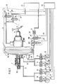
- Fig. 1 shows a motor vehicle brake system with a vacuum brake booster 1, which is connected via a piston rod 11 in a known manner to a brake pedal 12.
- a tandem master brake cylinder 2 On the side of the vacuum brake booster 1 facing away from the piston rod 11, a tandem master brake cylinder 2 is provided, which is connected to a brake fluid reservoir, not shown.
- a first and a second brake circuit 17 and 16 are connected to the pressure chambers 80, 90 of the tandem master cylinder 2.
- the first brake circuit 17 connects the wheel brake cylinders of the two wheel brakes 20 and 21, which are only shown schematically, to the tandem master brake cylinder 2 via two solenoid valves 18, 19, which are designed as 2/2-way valves. Each of the two solenoid valves 18, 19 is here assigned to one of the two wheel brakes 20 or 21.
- the second brake circuit 16 connects the wheel brake cylinders of the further two wheel brakes 22, 23, also shown only schematically, to the tandem master brake cylinder 2 via two further solenoid valves 14, 24, which are also designed as 2/2-way valves.
- a sensor 25, 26, 27 and 28 is assigned to the front and rear wheel brakes 20, 21, 22 and 23, which are connected to central control electronics 33 via corresponding signal lines 29, 30, 31 and 32.
- the sensors 25, 26, 27 and 28, which can be designed, for example, as inductive sensors, monitor the wheel turning behavior and deliver corresponding signals to the control electronics 33 via the signal lines 29, 30, 31 and 32.
- the control electronics 33 are connected via control lines 34, 35, 36, 37 to the solenoid valves 18, 19 and 14, 24 in order to actuate them in dependence on the sensor signals.
- Pneumatic lines 38, 43 connect pneumatic means - valve arrangements 39, 40 to the vacuum brake booster 1, which, depending on the control signals of the control electronics 33, enable evacuation or venting of working chambers of the vacuum brake booster 1, which are not described in detail.
- the first valve arrangement 39 is formed by two 2/2-way valves 391, 392, which are connected to the control electronics 37 by means of control lines 44, 45.
- the atmosphere-switching 2/2-way valve 392 is preferably designed as a normally closed solenoid valve, while as the vacuum-switching 2/2-way valve 391 a normally open solenoid valve is used, the input of which is connected to a vacuum source 42 via a check valve 41.
- a second vacuum-switching, normally closed 2/2-way valve 402 of the second valve arrangement 40 is also connected to the vacuum source 42 and can be excited by the central control electronics 33 via a third control line 47.
- the second valve arrangement 40 also comprises a second, 2/2-way valve 401, which switches the atmosphere and is designed as a normally open electromagnetic valve and is connected to the control electronics 33 via a fourth control line 46.
- a pressure sensor 15 is connected to one of the two working chambers of the vacuum brake booster 1, the output signal of which is supplied to the central control electronics 33 via a signal line 13.
- the vacuum brake booster 1 has two shell-shaped housing parts 48, 49 assembled with their open sides, which form an amplifier housing 10.
- the left in Fig. 2 provided with a pneumatic connection 55 housing part 48 is fixedly connected to the tandem master cylinder 2, while the right housing part 49 has a central guide piece 50 which keeps a control valve housing 51 of the vacuum brake booster 1 slidably and vacuum-tight.
- the control valve housing 51 has a rear control housing part 52 which extends out of the vacuum brake booster 1 in the direction of the brake pedal 12, and a front control housing part 53 which is arranged essentially inside the vacuum brake booster 1.
- the interior of the booster housing 10 is divided into a first working chamber 5 and a second working chamber 6 by a movable wall 7 arranged therein, consisting of a diaphragm plate 8 and a rolling diaphragm 9 lying thereon is ventilated.
- the valve arrangement 58 which is known per se, is operated by a piston rod 11 Connected valve piston 54 is actuated, which transmits the actuating force introduced via the brake pedal 12 via a transmission disk 59, a rubber-elastic reaction disk 60 and a pressure plate 61 to a force output member - push rod 62.
- a return spring 57 is provided, which is clamped between the front housing part 48 and the diaphragm plate 8.
- a flange 80 is fastened by means of screw connections 79 with the interposition of a seal 81 and has a pneumatic connection 56 to which the pneumatic line 43 leading from the second valve arrangement 40 is connected.
- the rear control housing part 52 is preferably provided with an axial extension 64, which is axially guided in a sealed manner in the flange 80 by means of a sealing ring 65.
- the fastening elements 75 for a flange 80 supporting a motor vehicle body wall delimits, with the rear control housing part 52, a pneumatic space 63 which can be ventilated or evacuated depending on the control signals of the central control electronics 33.
- the transmission area between the rear control housing part 52 and its axial extension 64 has radial openings 74.
- the valve arrangement 58 consisting of a first sealing seat 69 formed on the front control housing part 83, a second sealing seat 70 formed on the valve piston 54 and a poppet valve 87 biased in the closing direction by means of a valve spring 68 is actuated directly by means of an intermediate rod 77, the pedal-side end of which has a guide collar 66 which is guided in a bore 78 in the axial extension 64.
- the sealing of the guide collar 66 is ensured by a sealing sleeve 67 sliding on the wall of the bore 78, the piston rod 11, which is coupled to the brake pedal 12, is mounted on the pedal-side end of the intermediate rod 77.
- the poppet valve 87 is guided within the control valve housing 51 by means of a guide element 72 which is supported on the rear control housing part 52 and on which a compression spring 73 is supported, which prestresses the outer edge of the poppet valve 87 in the direction of the front control housing part 53. Finally, a piston return spring 71 is arranged between the valve piston 54 and the front control housing part 53 and determines the response force of the vacuum brake booster 1.
- the control group shown in Fig. 3 differs from that shown in Fig. 2 mainly in that the control valve housing 51 is formed in one piece, the first sealing seat 69 is arranged in the release position of the vacuum brake booster 1 at a distance from the poppet valve 87, which is a free travel of the device.
- the ventilable or evacuable space 63 is outwardly by means of a bellows 82 attached to the flange 86 sealed, whose symmetrically opposite radial fastening region 83 cooperate with the fastening elements 75 in the sense that the fastening elements 75 extend through through openings 84 formed in the fastening regions 83 in order to be screwed to the body wall during assembly.
- the bellows 82 has at its end facing away from the flange 80 an annular bead 85 which is buttoned in a radial groove 86 formed in the piston rod 11.
- the actuation and release of the brakes thus works like a known vacuum brake booster.
- the driver is directly informed of the occurrence of a slip control phase by pulsing the brake pedal.
Landscapes
- Engineering & Computer Science (AREA)
- Transportation (AREA)
- Mechanical Engineering (AREA)
- Physics & Mathematics (AREA)
- Fluid Mechanics (AREA)
- Braking Systems And Boosters (AREA)
- Regulating Braking Force (AREA)
Claims (15)
- Système de freinage pour véhicule automobile, comprenant, d'une part, un amplificateur d'effort de freinage à dépression (1) disposé, de façon à coopérer avec eux, entre une pédale de frein (12) et un maître-cylindre de frein (2) et comportant au moins deux chambres de travail (5, 6) qui sont séparées l'une de l'autre par une paroi mobile (7) et dont la première est agencée de façon à pouvoir être reliée à une source de dépression (42) et la seconde est agencée de façon à pouvoir être mise à l'atmosphère par l'intermédiaire d'une valve de commande (87) agencée de façon à pouvoir être actionnée au moyen d'une tige de piston (11) accouplée à la pédale de frein (12), en vue de produire une force d'amplification proportionnelle à la force exercée sur la pédale de frein, tandis que des cylindres de freins de roues (20, 21, 22, 23) sont raccordés à une chambre de pression primaire et une chambre de pression secondaire du maître-cylindre de frein (2) par l'intermédiaire de conduites de freinage (16,17), et, d'autre part, des capteurs (25, 26, 27, 28), associés aux roues à freiner, qui relèvent le comportement des roues en rotation, en vue d'établir l'existence d'un blocage, et dont des signaux de sortie peuvent être envoyés à un circuit électronique central de régulation (33), des signaux de commande de ce dernier permettant de commander des valves d'entrée et de sortie d'agent de pression (18, 19, 14, 24), à commande électromagnétique, insérées dans les conduites de freinage (16, 17) en vue de la régulation du glissement, tandis qu'il est prévu des moyens pneumatiques (39, 40) qui, dans un cas de régulation de glissement, permettent une mise à l'atmosphère de la première chambre de travail (5) et/ou une mise en dépression de la seconde chambre de travail (6), afin de rendre la force d'amplification de l'amplificateur d'effort de freinage à dépression (1) active ou inactive dans une direction opposée à la direction d'actionnement du maître-cylindre de frein (2), caractérisé en ce que les moyens pneumatiques (40) sont raccordés à la seconde chambre de travail (6) au moyen d'une bride (80), prévue sur le boîtier d'amplificateur (10), qui est pourvue d'un raccord pneumatique (56) et qui délimite avec le boîtier d'amplificateur (10), ainsi qu'avec un boîtier de valve de commande (51), une chambre (63) pouvant être mise à l'atmosphère ou être mise en dépression.
- Système de freinage, pour véhicule automobile, suivant la revendication 1, caractérisé en ce que les moyens pneumatiques (39, 40) sont constitués chacun de deux valves à 2 voies/2 positions (391, 392 ou 401,402) qui sont agencées de façon à pouvoir être mises sous tension par des signaux de commande du circuit électronique central de régulation (33).
- Système de freinage, pour véhicule automobile, suivant la revendication 2, caractérisé en ce que les valves à 2 voies/2 positions (391, 392, 401, 402) sont réalisées sous la forme de valves électromagnétiques ouvertes en l'absence de courant (391, 402) et de valves électromagnétiques fermées en l'absence de courant (392, 402).
- Système de freinage, pour véhicule automobile, suivant la revendication 1, caractérisé en ce que les moyens pneumatiques (39, 40) sont constitués chacun d'une valve électromagnétique à 3 voies/2 positions raccordées chacune à l'une des deux chambres de travail (5 ou 6).
- Système de freinage, pour véhicule automobile, suivant la revendication 1, caractérisé en ce que la bride (80) porte des moyens (75) de fixation sur une paroi de carrosserie.
- Système de freinage, pour véhicule automobile, suivant la revendication 1 ou 5, caractérisé en ce que le boîtier de valve de commande (51) comporte un prolongement axial (64) qui est guidé de manière étanche dans la bride (80).
- Système de freinage, pour véhicule automobile, suivant la revendication 6, caractérisé en ce que le prolongement axial (64) comporte un alésage (78) dans lequel est guidé, de façon à pouvoir y être déplacé en translation de manière étanche, un bourrelet de guidage (66) d'une tige intermédiaire (77) qui actionne directement la valve de commande (58) et qui est reliée à la tige de piston (11) de façon à coopérer avec cette dernière.
- Système de freinage, pour véhicule automobile, suivant la revendication 6 ou 7, caractérisé en ce que le prolongement axial (64) est réalisé d'une pièce avec le boîtier de valve de commande (51, 52), tandis que, dans la zone de raccordement entre le boîtier de valve de commande (52) et le prolongement (64), il est prévu des passages (74) qui permettent que la chambre intérieure (76) de la valve de commande (58) soit soumise à l'action pneumatique de la pression régnant dans la chambre (63).
- Système de freinage, pour véhicule automobile, suivant la revendication 7, caractérisé en ce que l'étanchéité du bourrelet de guidage (66) vis-à-vis de la paroi de l'alésage (78) est assurée au moyen d'une coupelle d'étanchéité (67).
- Système de freinage, pour véhicule automobile, suivant la revendication 1 ou 5, caractérisé en ce que la bride (80) est fixée sur le boîtier d'amplificateur (10), avec interposition d'une garniture d'étanchéité (81), au moyen de jonctions par vissage (79).
- Système de freinage, pour véhicule automobile, suivant la revendication 1 ou 5, caractérisé en ce que la chambre (63) est séparée de l'atmosphère environnante par un soufflet (82) qui s'étend entre la bride (80) et la tige de piston (11).
- Système de freinage, pour véhicule automobile, suivant la revendication 11, caractérisé en ce que le soufflet (82) comprend au moins deux zones radiales de fixation (83) qui sont réalisées d'une manière symétriquement opposée et qui coopèrent avec les éléments de fixation (75) montés sur la bride (80).
- Système de freinage, pour véhicule automobile, suivant la revendication 12, caractérisé en ce que les zones de fixation (83) comportent des ouvertures (84) pour le passage des éléments de fixation (75).
- Système de freinage, pour véhicule automobile, suivant l'une des revendications 11 à 13, caractérisé en ce qu'à son extrémité située à l'opposé de la bride (80), le soufflet (82) comporte un bourrelet tubulaire (85) qui est enclenché dans une gorge radiale (86) ménagée dans la tige de piston (11).
- Système de freinage, pour véhicule automobile, suivant l'une des revendications précédentes, caractérisé en ce qu'un capteur de pression (15), dont le signal de sortie peut être envoyé au circuit électronique central de régulation (33), est raccordé à l'une des deux chambres de travail (5, 6).
Applications Claiming Priority (2)
| Application Number | Priority Date | Filing Date | Title |
|---|---|---|---|
| DE3817785A DE3817785A1 (de) | 1988-05-26 | 1988-05-26 | Kraftfahrzeugbremsanlage |
| DE3817785 | 1988-05-26 |
Publications (3)
| Publication Number | Publication Date |
|---|---|
| EP0343365A2 EP0343365A2 (fr) | 1989-11-29 |
| EP0343365A3 EP0343365A3 (en) | 1990-06-13 |
| EP0343365B1 true EP0343365B1 (fr) | 1993-01-20 |
Family
ID=6355103
Family Applications (1)
| Application Number | Title | Priority Date | Filing Date |
|---|---|---|---|
| EP89106787A Expired - Lifetime EP0343365B1 (fr) | 1988-05-26 | 1989-04-15 | Installation de freinage pour véhicules |
Country Status (4)
| Country | Link |
|---|---|
| US (1) | US4966420A (fr) |
| EP (1) | EP0343365B1 (fr) |
| JP (1) | JPH0220461A (fr) |
| DE (2) | DE3817785A1 (fr) |
Families Citing this family (18)
| Publication number | Priority date | Publication date | Assignee | Title |
|---|---|---|---|---|
| EP0386179B1 (fr) * | 1988-07-01 | 1992-10-21 | ALFRED TEVES GmbH | Circuit de freinage de vehicule a moteur a systeme anti-blocage |
| DE3910285C2 (de) * | 1989-03-30 | 1996-12-19 | Teves Gmbh Alfred | Hydraulische Bremsanlage für Kraftfahrzeuge mit einer Einrichtung zur Regelung des Antriebsschlupfes |
| DE3933636A1 (de) * | 1989-06-13 | 1991-04-11 | Teves Gmbh Alfred | Betaetigungseinheit fuer eine blockiergeschuetzte kraftfahrzeugbremsanlage |
| DE3920766C3 (de) * | 1989-06-24 | 2002-09-19 | Continental Teves Ag & Co Ohg | Unterdruckbremskraftverstärker für eine schlupfgeregelte Bremsanlage |
| DE3931469A1 (de) * | 1989-09-21 | 1991-04-04 | Teves Gmbh Alfred | Blockiergeschuetzte hydraulische bremsanlage |
| DE3943002A1 (de) * | 1989-12-27 | 1991-07-04 | Lucas Ind Plc | Fahrzeugbremsanlage |
| DE4004065A1 (de) * | 1990-02-10 | 1991-08-14 | Teves Gmbh Alfred | Blockiergeschuetzte kraftfahrzeugbremsanlage und verfahren zum betreiben einer solchen anlage |
| JPH0680064A (ja) * | 1992-07-13 | 1994-03-22 | Sumitomo Electric Ind Ltd | 液圧制御装置 |
| FR2702437B1 (fr) * | 1993-03-10 | 1995-04-28 | Alliedsignal Europ Services | Dispositif de freinage assisté à commande automatique simplifiée. |
| US5312173A (en) * | 1993-05-28 | 1994-05-17 | Alliedsignal Inc. | Control valve actuator |
| DE4401082A1 (de) * | 1994-01-15 | 1995-07-20 | Daimler Benz Ag | Verfahren zum Vermindern des Ruckens eines Kraftfahrzeugs bei zum Stillstand führenden Bremsvorgängen |
| DE4436297C2 (de) * | 1994-10-11 | 1998-10-08 | Lucas Ind Plc | Elektronisch gesteuerter Bremskraftverstärker und Verfahren zu dessen Betrieb |
| US5484193A (en) * | 1994-10-21 | 1996-01-16 | Kelsey-Hayes | Single channel best effort anti-lock brake system |
| DE19541101A1 (de) * | 1995-11-06 | 1997-05-07 | Teves Gmbh Alfred | Verfahren zum Betrieb eines pneumatischen Bremskraftverstärkers |
| AU708569B3 (en) * | 1997-10-30 | 1999-08-05 | Kalam, Professor A. | Induction of power (in motor) from a stationary object (stator) to a rotary object (rotor) with automatic and sensorless speed and position detection |
| US6073535A (en) * | 1998-08-07 | 2000-06-13 | Robert Bosch Corporation | Guard for a valve body of a brake booster |
| US6386648B1 (en) * | 2000-10-27 | 2002-05-14 | Robert Bosch Corporation | Master cylinder and brake booster for a brake system |
| DE102008010704A1 (de) | 2008-02-22 | 2009-08-27 | Lucas Automotive Gmbh | Technik zur elektronischen Bremskraftverteilung bei einer mit einer hydraulischen Bremskraftverstärkung ausgerüsteten Fahrzeugbremsanlage |
Family Cites Families (10)
| Publication number | Priority date | Publication date | Assignee | Title |
|---|---|---|---|---|
| DE1780667A1 (de) * | 1967-04-08 | 1973-07-19 | Teldix Gmbh | Antiblockierregelsystem fuer eine kolbengesteuerte hydraulische bremsanlage |
| US3498682A (en) * | 1967-09-05 | 1970-03-03 | Eaton Yale & Towne | Braking system |
| JPS4820353B1 (fr) * | 1968-06-22 | 1973-06-20 | ||
| US3559532A (en) * | 1968-10-23 | 1971-02-02 | Stanley I Macduff | Travel servomotor |
| GB1415192A (en) * | 1972-03-18 | 1975-11-26 | Lucas Industries Ltd | Braking systems for vehicles |
| DE3317629A1 (de) * | 1983-05-14 | 1984-11-15 | Alfred Teves Gmbh, 6000 Frankfurt | Verfahren zur steuerung einer schlupfgeregelten bremsanlage und vorrichtung zur durchfuehrung des verfahrens |
| DE3428869A1 (de) * | 1984-08-04 | 1986-02-13 | Alfred Teves Gmbh, 6000 Frankfurt | Bremsschlupfgeregelte bremsanlage |
| DE3627000C2 (de) * | 1986-08-08 | 1998-05-20 | Teves Gmbh Alfred | Bremsanlage mit Schlupfregelung |
| DE3638510C2 (de) * | 1986-11-11 | 1995-04-13 | Teves Gmbh Alfred | Bremsanlage mit Schlupfregelung |
| DE3641105A1 (de) * | 1986-12-02 | 1988-06-16 | Teves Gmbh Alfred | Kraftfahrzeugbremsvorrichtung |
-
1988
- 1988-05-26 DE DE3817785A patent/DE3817785A1/de not_active Withdrawn
-
1989
- 1989-04-15 EP EP89106787A patent/EP0343365B1/fr not_active Expired - Lifetime
- 1989-04-15 DE DE8989106787T patent/DE58903318D1/de not_active Expired - Fee Related
- 1989-05-15 US US07/351,978 patent/US4966420A/en not_active Expired - Fee Related
- 1989-05-25 JP JP1132536A patent/JPH0220461A/ja active Pending
Also Published As
| Publication number | Publication date |
|---|---|
| JPH0220461A (ja) | 1990-01-24 |
| DE3817785A1 (de) | 1989-12-07 |
| US4966420A (en) | 1990-10-30 |
| DE58903318D1 (de) | 1993-03-04 |
| EP0343365A2 (fr) | 1989-11-29 |
| EP0343365A3 (en) | 1990-06-13 |
Similar Documents
| Publication | Publication Date | Title |
|---|---|---|
| EP0343365B1 (fr) | Installation de freinage pour véhicules | |
| DE3920766C2 (de) | Unterdruckbremskraftverstärker für eine schlupfgeregelte Bremsanlage | |
| EP0435113B1 (fr) | Installation de freinage de véhicule | |
| DE4208496C1 (fr) | ||
| DE3641105A1 (de) | Kraftfahrzeugbremsvorrichtung | |
| EP0758966A1 (fr) | Systeme d'actionnement de frein regulable electroniquement | |
| WO1994011226A1 (fr) | Systeme d'assistance de freinage a depression | |
| DE4410699C2 (de) | Hydraulische Bremsanlage für Kraftfahrzeuge | |
| DE68907544T2 (de) | Kraftfahrzeugbremssysteme. | |
| EP1853469A1 (fr) | Systeme de freinage pour vehicules automobiles | |
| EP0722397B1 (fr) | Systeme de freinage pour vehicules automobiles | |
| DE3838848A1 (de) | Unterdruck-bremskraftverstaerker | |
| EP1051316A1 (fr) | Dispositif de transmission de force de freinage, notamment pour vehicules a moteur | |
| DE69202921T2 (de) | Pneumatischer Servomotor. | |
| DE19624376A1 (de) | Bremsanlage für Kraftfahrzeuge | |
| EP0386179B1 (fr) | Circuit de freinage de vehicule a moteur a systeme anti-blocage | |
| DE4024384A1 (de) | Blockiergeschuetzte kraftfahrzeugbremsanlage | |
| DE4028925A1 (de) | Betaetigungseinheit fuer hydraulische bremsanlagen | |
| DE3822260A1 (de) | Blockiergeschuetzte kraftfahrzeugbremsanlage | |
| EP0360013B1 (fr) | Installation de freinage à anti-blocage pour véhicules automobiles | |
| DE3822261A1 (de) | Bremsbetaetigungseinheit fuer kraftfahrzeuge | |
| DE19727654B4 (de) | Hydraulisches Ventil | |
| DE3916640A1 (de) | Betaetigungseinheit fuer eine blockiergeschuetzte kraftfahrzeugbremsanlage | |
| DE4123637A1 (de) | Blockiergeschuetzte kraftfahrzeugbremsanlage | |
| DE3908062A1 (de) | Blockiergeschuetzte kraftfahrzeugbremsanlage |
Legal Events
| Date | Code | Title | Description |
|---|---|---|---|
| PUAI | Public reference made under article 153(3) epc to a published international application that has entered the european phase |
Free format text: ORIGINAL CODE: 0009012 |
|
| 17P | Request for examination filed |
Effective date: 19890415 |
|
| AK | Designated contracting states |
Kind code of ref document: A2 Designated state(s): DE ES FR GB IT |
|
| PUAL | Search report despatched |
Free format text: ORIGINAL CODE: 0009013 |
|
| AK | Designated contracting states |
Kind code of ref document: A3 Designated state(s): DE ES FR GB IT |
|
| 17Q | First examination report despatched |
Effective date: 19910708 |
|
| ITF | It: translation for a ep patent filed | ||
| GRAA | (expected) grant |
Free format text: ORIGINAL CODE: 0009210 |
|
| AK | Designated contracting states |
Kind code of ref document: B1 Designated state(s): DE ES FR GB IT |
|
| PG25 | Lapsed in a contracting state [announced via postgrant information from national office to epo] |
Ref country code: GB Effective date: 19930120 Ref country code: FR Effective date: 19930120 Ref country code: ES Free format text: THE PATENT HAS BEEN ANNULLED BY A DECISION OF A NATIONAL AUTHORITY Effective date: 19930120 |
|
| REF | Corresponds to: |
Ref document number: 58903318 Country of ref document: DE Date of ref document: 19930304 |
|
| EN | Fr: translation not filed | ||
| GBV | Gb: ep patent (uk) treated as always having been void in accordance with gb section 77(7)/1977 [no translation filed] |
Effective date: 19930120 |
|
| PLBE | No opposition filed within time limit |
Free format text: ORIGINAL CODE: 0009261 |
|
| STAA | Information on the status of an ep patent application or granted ep patent |
Free format text: STATUS: NO OPPOSITION FILED WITHIN TIME LIMIT |
|
| PG25 | Lapsed in a contracting state [announced via postgrant information from national office to epo] |
Ref country code: DE Effective date: 19940101 |
|
| 26N | No opposition filed | ||
| PG25 | Lapsed in a contracting state [announced via postgrant information from national office to epo] |
Ref country code: IT Free format text: LAPSE BECAUSE OF NON-PAYMENT OF DUE FEES;WARNING: LAPSES OF ITALIAN PATENTS WITH EFFECTIVE DATE BEFORE 2007 MAY HAVE OCCURRED AT ANY TIME BEFORE 2007. THE CORRECT EFFECTIVE DATE MAY BE DIFFERENT FROM THE ONE RECORDED. Effective date: 20050415 |