EP0343077B1 - Autonomer Modul für die Intensivpflege und Reanimation - Google Patents
Autonomer Modul für die Intensivpflege und Reanimation Download PDFInfo
- Publication number
- EP0343077B1 EP0343077B1 EP89401376A EP89401376A EP0343077B1 EP 0343077 B1 EP0343077 B1 EP 0343077B1 EP 89401376 A EP89401376 A EP 89401376A EP 89401376 A EP89401376 A EP 89401376A EP 0343077 B1 EP0343077 B1 EP 0343077B1
- Authority
- EP
- European Patent Office
- Prior art keywords
- leg
- point
- module according
- ground
- folding
- Prior art date
- Legal status (The legal status is an assumption and is not a legal conclusion. Google has not performed a legal analysis and makes no representation as to the accuracy of the status listed.)
- Expired - Lifetime
Links
- 230000000712 assembly Effects 0.000 claims description 2
- 238000000429 assembly Methods 0.000 claims description 2
- 230000002427 irreversible effect Effects 0.000 claims description 2
- 238000005096 rolling process Methods 0.000 description 12
- 210000000056 organ Anatomy 0.000 description 7
- 230000008901 benefit Effects 0.000 description 5
- 101100536354 Drosophila melanogaster tant gene Proteins 0.000 description 2
- 230000000694 effects Effects 0.000 description 2
- 230000000747 cardiac effect Effects 0.000 description 1
- 238000000605 extraction Methods 0.000 description 1
- 230000005484 gravity Effects 0.000 description 1
- 229910001234 light alloy Inorganic materials 0.000 description 1
- 239000007788 liquid Substances 0.000 description 1
- 238000004519 manufacturing process Methods 0.000 description 1
- 230000001575 pathological effect Effects 0.000 description 1
- 230000000241 respiratory effect Effects 0.000 description 1
- 238000000926 separation method Methods 0.000 description 1
- 230000035939 shock Effects 0.000 description 1
Images


Classifications
-
- A—HUMAN NECESSITIES
- A61—MEDICAL OR VETERINARY SCIENCE; HYGIENE
- A61G—TRANSPORT, PERSONAL CONVEYANCES, OR ACCOMMODATION SPECIALLY ADAPTED FOR PATIENTS OR DISABLED PERSONS; OPERATING TABLES OR CHAIRS; CHAIRS FOR DENTISTRY; FUNERAL DEVICES
- A61G1/00—Stretchers
- A61G1/04—Parts, details or accessories, e.g. head-, foot-, or like rests specially adapted for stretchers
- A61G1/052—Struts, spars or legs
- A61G1/056—Swivelling legs
- A61G1/0562—Swivelling legs independently foldable, i.e. at least part of the leg folding movement is not simultaneous
-
- A—HUMAN NECESSITIES
- A61—MEDICAL OR VETERINARY SCIENCE; HYGIENE
- A61G—TRANSPORT, PERSONAL CONVEYANCES, OR ACCOMMODATION SPECIALLY ADAPTED FOR PATIENTS OR DISABLED PERSONS; OPERATING TABLES OR CHAIRS; CHAIRS FOR DENTISTRY; FUNERAL DEVICES
- A61G1/00—Stretchers
- A61G1/02—Stretchers with wheels
- A61G1/0206—Stretchers with wheels characterised by the number of supporting wheels if stretcher is extended
- A61G1/0212—2 pairs having wheels within a pair on the same position in longitudinal direction, e.g. on the same axis
-
- A—HUMAN NECESSITIES
- A61—MEDICAL OR VETERINARY SCIENCE; HYGIENE
- A61G—TRANSPORT, PERSONAL CONVEYANCES, OR ACCOMMODATION SPECIALLY ADAPTED FOR PATIENTS OR DISABLED PERSONS; OPERATING TABLES OR CHAIRS; CHAIRS FOR DENTISTRY; FUNERAL DEVICES
- A61G1/00—Stretchers
- A61G1/02—Stretchers with wheels
- A61G1/0206—Stretchers with wheels characterised by the number of supporting wheels if stretcher is extended
- A61G1/0225—Stretchers with wheels characterised by the number of supporting wheels if stretcher is extended other configuration, e.g. odd number of wheels
-
- A—HUMAN NECESSITIES
- A61—MEDICAL OR VETERINARY SCIENCE; HYGIENE
- A61G—TRANSPORT, PERSONAL CONVEYANCES, OR ACCOMMODATION SPECIALLY ADAPTED FOR PATIENTS OR DISABLED PERSONS; OPERATING TABLES OR CHAIRS; CHAIRS FOR DENTISTRY; FUNERAL DEVICES
- A61G1/00—Stretchers
- A61G1/02—Stretchers with wheels
- A61G1/0237—Stretchers with wheels having at least one swivelling wheel, e.g. castors
-
- A—HUMAN NECESSITIES
- A61—MEDICAL OR VETERINARY SCIENCE; HYGIENE
- A61G—TRANSPORT, PERSONAL CONVEYANCES, OR ACCOMMODATION SPECIALLY ADAPTED FOR PATIENTS OR DISABLED PERSONS; OPERATING TABLES OR CHAIRS; CHAIRS FOR DENTISTRY; FUNERAL DEVICES
- A61G1/00—Stretchers
- A61G1/02—Stretchers with wheels
- A61G1/025—Stretchers with wheels having auxiliary wheels, e.g. wheels not touching the ground in extended position
- A61G1/0262—Stretchers with wheels having auxiliary wheels, e.g. wheels not touching the ground in extended position having loading wheels situated in the front during loading
-
- A—HUMAN NECESSITIES
- A61—MEDICAL OR VETERINARY SCIENCE; HYGIENE
- A61G—TRANSPORT, PERSONAL CONVEYANCES, OR ACCOMMODATION SPECIALLY ADAPTED FOR PATIENTS OR DISABLED PERSONS; OPERATING TABLES OR CHAIRS; CHAIRS FOR DENTISTRY; FUNERAL DEVICES
- A61G1/00—Stretchers
- A61G1/02—Stretchers with wheels
- A61G1/0293—Stretchers with wheels stretcher supports with wheels, e.g. used for stretchers without wheels
-
- A—HUMAN NECESSITIES
- A61—MEDICAL OR VETERINARY SCIENCE; HYGIENE
- A61G—TRANSPORT, PERSONAL CONVEYANCES, OR ACCOMMODATION SPECIALLY ADAPTED FOR PATIENTS OR DISABLED PERSONS; OPERATING TABLES OR CHAIRS; CHAIRS FOR DENTISTRY; FUNERAL DEVICES
- A61G2210/00—Devices for specific treatment or diagnosis
- A61G2210/30—Devices for specific treatment or diagnosis for intensive care
Definitions
- the present invention relates to an autonomous intensive care and resuscitation module usable mainly during the transport of the sick and injured to a care center.
- the transportation of the sick and injured to the health center requires the use of specially equipped vehicles with all the equipment necessary for resuscitation and medical assistance.
- the operating cost of these vehicles, particularly in the case of air transport vehicles, is very high, this due to their specific use on the one hand, and on the other hand to the high degree of technicality of the medical equipment with which they are equipped. .
- This chassis is made up of articulated cross rods secured to a lower frame provided with rolling members and an upper frame detachably carrying the stretcher.
- a jack is added to the cross rods to, by closing or opening the angle they form, adjust the height of the stretcher.
- the lower frame is a nuisance for the rescuer, and it is not possible with the configuration given to the chassis to tilt the stretcher according to the appropriate position required for an injured person in pathological shock.
- FR-A 2 506 153 Also known from FR-A 2 506 153 is a stretcher and its ambulance support trolley. This stretcher and this support chase are not designed to receive medical assistance equipment so that they cannot be assimilated to an autonomous intensive care module.
- the support frame comprises a cover provided with legs terminated by sets of wheels.
- the legs are articulated to the support frame.
- the legs can only occupy two stable positions, namely: a fully extended position and a fully folded position so that it is not possible with this configuration to adjust the height of the stretcher.
- these legs are not associated with motor members in particular to ensure their folding during the introduction into the ambulance and this folding movement is only ensured by cooperation with a roller during the introduction into the ambulance .
- the change in position of the legs is accompanied by a decentering of the support polygon relative to the stretcher.
- the object of the present invention is to overcome the drawbacks mentioned above.
- the independent intensive care and resuscitation module comprising a removable tray for receiving the sick and injured, medical assistance and resuscitation equipment and a base provided with support bodies on the ground, the said module comprising a beam which supports the various equipment and the platform and which is supported above the ground in an adjustable manner in height and in inclination by the base which is constituted by at least two legs associated with actuating and guiding means which imprint them simultaneously or independently of each other a movement of folding and deployment under the beam
- the said module is characterized in that the movement of deployment and folding of each leg is formed by the combination of a translational movement with a rotational movement, that during folding, the rotational movement takes place under and towards the beam and towards the end of the latter that the leg in the deployed position supports while the translational movement takes place under the beam and towards the other end and that during deployment the translational movement takes place under the beam and towards the other end and that during deployment the translational movement takes place under the beam in the direction of the end and that the jamb in the deployed position then supports that the rotation
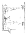
- the independent intensive care and resuscitation module comprises a hollow central beam 1, made of light alloy on which is removably disposed a plate 2 for receiving the wounded or sick, this plate possibly being a hard surface.
- the beam is laterally equipped with the equipment necessary for medical assistance and resuscitation and is supported above the ground of my adjustable in height and / or in inclination by a folding base 3 which can be deployed under it so as to be able to bring it up to the floor of the transport vehicle, place the corresponding end on this floor and then proceed with the introduction complete of the module and this in conjunction with the folding of the base and also so that the reverse operation can be carried out.
- the module is equipped with omni-directional rolling members 4 for coming to bear on the floor of the transport vehicle, during the loading or unloading operation of the module.
- these rolling members are mounted on a structure 5 which can be partially extracted from the beam or fully retracted by translational movement along an axis parallel to the longitudinal median axis of the beam. This structure is actuated by a drive member 6.
- the running gear and the structure which carries it can be arranged in front of the beam to facilitate on the one hand, the loading of the module and on the other hand, to separate as far as possible from the body of the vehicle the legs of so that the latter cannot come into contact with the vehicle during folding or deployment. Thereafter, the structure and the rolling members 4 may be brought back into the beam 1 for reasons of space.
- the structure 5 is constituted by a horizontal wall provided with two vertical lateral wings by the intermediary diary of which it is integral with guiding members in translation constituted for example by slides 5A. These guide rails are parallel to the longitudinal median axis of the beam.
- the rolling members are fixed to this wall by screws or any other means. These organs extend entirely under this wall.
- the actuating motor member is for example constituted by a hydraulic cylinder fixed on the one hand, to the beam by means of a yoke, and on the other hand, to the structure 5 always by means of a screed.
- This hydraulic cylinder is connected to an appropriate hydraulic circuit, housed in the beam comprising hydraulic distributors associated with manual controls. By means of one of these commands and of the associated distributor, it is possible to cause the deployment or the retraction of the rod of the jack 6 and to cause the extraction or the retraction of or in the beam of the rolling members 5A and structure 5.
- the mid-length beam is equipped with two lateral support members on the ground each constituted by a roller 9.
- the base 3 of the module comprises at least two legs 7 which each carry at the lower end a member 8 for supporting the ground preferably comprising 8A rollers, omnidirectional and which each cooperate with actuation and guide means which either maintain them in position where either a deployment or folding movement is formed by the combination of a translational movement and a rotational movement.
- Each leg moves in a vertical plane parallel to the median longitudinal axis of the beam.
- the folding movement of the legs is carried out so that the support members on the ground are each arranged in the vicinity of the corresponding end of the beam, or in withdrawal, when said legs are fully folded.
- the module preferably rests on the ground always by means of the support members 8, but according to another embodiment, it can rest on the ground by means of the beam 1. In this case, the members 8 can be completely erased in the beam.
- the two legs are kinematically independent from each other, which makes it possible to deploy or fold them independently of one another.
- the legs can be maintained in a fixed position regardless of the position of the other leg which can be, at this time, mobile or even stationary. This characteristic offers several advantages, in particular that of being able to arrange the beam 1 and the plate 2 which it carries in an incline or a slope.
- the movement of the front jamb will take place until the rollers of the member 8 reach the vehicle floor so as to be able to come to bear on the latter by movement of introduction of the module.
- the introduction of the module will continue until the rollers 9 come to bear on the floor, after which the folding movement of the rear leg can be operated.
- the projection of the center of gravity of the module is contained in the support polygon defined by the middle rollers and the front rollers or else, if this projection is outside, is located in the immediate vicinity of this polygon.
- the module After complete folding of the rear leg, the module can be fully inserted into the vehicle and locked in position by lashing.
- the two assemblies each formed by a leg and by its actuating and guiding means are respectively arranged under and in the beam and preferably, on either side of a vertical median plane containing the longitudinal axis of the beam, so that during folding, the two legs can on the one hand penetrate partly into the beam to reduce the ground clearance and on the other hand, cannot come and collide.
- This arrangement also allows the production of a module of small length compatible with the dimensions of the transport volume of the transport vehicle.
- the trajectory of the lower end of each leg during folding and deployment is located on or below the straight line D normal to the beam and passing through said end considering the fully deployed jamb.
- the ground support members 8 can be kept apart from the vehicle body during deployment and folding. It should be noted that in the intermediate position, the lower end of the jamb is very little removed from this line D. For this reason, the support polygon defined by the support members 8 deforms very little during the folding or deployment of the legs 7, which makes it possible to obtain a constant degree of stability whatever the position of these legs.
- the second point of articulation 12 of the leg is located midway between the first point 10 and the lower end of the leg and the center of the arc of circumference along which this second point evolves is located in below the aforementioned straight line, and below the axis AA ′ along which the translational movement of the first articulation point takes place.
- point 11 is located at the intersection of the line D with the axis along which the first point evolves.
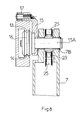
- the translational guide members comprise an upper rail 13 and a lower rail 14 both parallel to the median longitudinal axis of the beam 1, both arranged at a distance from one another along the same vertical plane with which cooperate in translational guidance a carriage 15 which receives the first articulation point 10.
- the carriage 15 is equipped with a rolling member 16 mounted idly on an axis.
- This rolling member is introduced in the interval between the rails 13 and 14 and is supported on one or the other rail depending on whether the support member 8 is supported or not on the ground.
- the carriage 15 is equipped with a guide mount 17 constituted by two juxtaposed rollers which both cooperate in rolling with an upper guide surface 18 formed on the upper rail 13.
- To the carriage 15 is fixed an axis 15A which extends perpendicular to the plane of evolution of the leg. This axis 15A engages in two bearings 7B made at the end of the leg.
- the axis 15A and the bearings 7B constitute the articulation point 10.
- the member 19 for guiding in rotation is constituted for example by an arm articulated by one of its ends to the leg 7 along the second articulation point 12. This arm is also articulated to the beam 1 according to point 11. Preferably, the arm 19 is extended beyond point 11 to cooperate with the drive means 26.
- this motor means 26 is constituted by a double-acting hydraulic cylinder mounted in the beam 1 fixed to the latter by its body, by means of a joint and fixed by its rod, by means of a joint in end of an extension 19A of the arm 19.
- This hydraulic jack is connected to the hydraulic circuit of the module and is associated with at least one distributor actuable from a manual or electric control.
- the motor means used is irreversible in the sense that an external action exerted on the latter cannot cause the movement of its motor elements, this in order to avoid the folding of the legs under the effect only of the weight of the module and the deployment of these under the effect of their own weight.
- this characteristic allows the legs to be kept in the intermediate position.
- the members 8 for supporting the ground are mounted in an articulated manner at the end of their leg along an axis normal to the plane of evolution of said leg and are integral with actuation means which imprint them with respect to a mark attached to their jamb a movement tilting joint deployment and folding movements of said leg, this tilting movement being performed so that the support member 8 relative to a mark attached to the beam is animated with a translational movement joint with the movement of deployment and folding of the jamb which carries it.
- the ground support members are always moved parallel to themselves.
- the support member 8 of each leg comprises a structure 20 which carries the rollers 8A, for example four or two in number.
- a pin 21 which engages in two end bearings 22 formed in the jamb 7 at its lower end.
- the first pinion 23 and the second pinion 24 are wedged respectively on the axis 15A and on the axis 21.
- each support member 8 is constituted by a rigid rod 27 housed in the leg associated with this member and fixed in an articulated manner, on the one hand by its lower end , to the structure of the support member 8 and on the other hand, by its upper end to the carriage 15 or to a lug fixed to the latter.
- This rod with the jamb defines a deformable parallelogram.
- the module as described is provided with fully autonomous energy sources.
- the hydraulic circuit of the module will be equipped with a hydraulic pump of the suction and discharge type associated with a reserve of liquid and actuated by an electric motor supplied from one or more electric batteries.
- These various organs will be housed in compartments formed in the beam.
- This module has the advantage of being light in weight and of reduced bulk, once its legs folded, which allows it to be transported by air means, for example by helicopters.
- the module can be transported by hand to the site of the accident, which provides the injured with an optimal technical environment while awaiting the means of transport.
- the wheels 8A of the module according to the invention may be removable so that they can be replaced by wheels of larger diameter, which makes it easier to move the module over rough terrain.
Landscapes
- Health & Medical Sciences (AREA)
- Life Sciences & Earth Sciences (AREA)
- Animal Behavior & Ethology (AREA)
- General Health & Medical Sciences (AREA)
- Public Health (AREA)
- Veterinary Medicine (AREA)
- Percussion Or Vibration Massage (AREA)
- Manipulator (AREA)
- Catching Or Destruction (AREA)
- Management, Administration, Business Operations System, And Electronic Commerce (AREA)
- Control Of Position, Course, Altitude, Or Attitude Of Moving Bodies (AREA)
- Invalid Beds And Related Equipment (AREA)
Claims (11)
- Autonomer Modul für die Intensivpflege und Reanimation, bestehend aus einer abnehmbaren Trage (2) zur Aufnahme von Kranken und Verletzten, aus medizinischen Behandlungs- und Reanimationsgerätschaften sowie einem mit Bodenstützelementen (4) ausgestatteten Untergestell (3), wobei der Modul aus einem Trägerelement (1) besteht, das die verschiedenen Gerätschaften und die Trage trägt und dessen Höhe und Neigung beim Stand auf dem Boden durch das Untergestell (3) regulierbar sind, welches aus mindestens zwei Stützgliedern (7) besteht, die durch Bewegungs- und Führungseinrichtungen so miteinander verbunden sind, daß deren Zusammenklappen und Aufklappen unter dem Trägerelement (1) gleichzeitig und unabhängig voneinander möglich ist, dadurch gekennzeichnet, daß das Zusammenklappen und Aufklappen der einzelnen Stützglieder (7) durch die Kombination von Parallelverschiebung und Rotationsbewegung erfolgt, daß beim Zusammenklappen die Rotationsbewegung unter dem und in Richtung auf das Trägerelement sowie in Richtung auf das äußere Ende desselben, das vom Stützglied in ausgeklappter Position gestützt wird, erfolgt, während die Parallelverschiebung unter dem Trägerelement und in Richtung auf das andere äußere Ende erfolgt, und daß beim Aufklappen die Parallelverschiebung unter dem Trägerelement und in Richtung auf das andere äußere Ende stattfindet, und daß beim Aufklappen eine Parallelverschiebung unter dem Trägerelement in Richtung auf das äußere Ende erfolgt, das vom ausgeklappten Stützglied getragen wird, während die Rotationsbewegung unter dem Trägerelement und im Abstand zu Letzterem stattfindet, und daß die Bewegungsbahn des unteren Endes eines jeden Stützgliedes (7), insbesondere während des Zusammenklappens auf einer Senkrechten zum Trägerelement und über dieses äußere Ende bei vollständigen Aufklappen des Stützgliedes verläuft.
- Autonomer Modul nach Anspruch 1, dadurch gekennzeichnet, daß die Stützglieder (7) und deren Bewegungseinrichtungen in zusammengeklappter Position teilweise oder vollständig im Trägerelement untergebracht sind, so daß die Bodenfreiheit reduziert wird.
- Autonomer Modul nach Anspruch 1, dadurch gekennzeichnet, daß die Bewegungs- und Führungseinrichtungen bestehen aus:- Führungselementen für Parallelverschiebung, die einer zur Längsachse des Trägerelementes parallel verlaufenden Achse folgen und die über einen ersten Anlenkpunkt (10) mit dem oberen Teil des Stützgliedes zusammenwirken;- einem Führungselement für Rotationsbewegung (19), das einen Kreisbogen um einen Punkt (11) beschreibt, der sich am äußeren Ende des Trägerelementes befindet oder in Bezug auf dasselbe leicht zurückgesetzt ist, und das über einen zweiten Anlenkpunkt (12) mit dem Stützglied zusammenwirkt, wobei sich dieser zweite Anlenkpunkt (12) zwischen dem ersten Anlenkpunkt und dem unteren Ende des Stützgliedes befindet;- einem Antriebselement (26), das zur Betätigung der Gesamteinheit sowohl die Führungselemente für die Rotation als auch die Führungselemente für die Parallelverschiebung unmittelbar antreibt.
- Autonomer Modul nach Anspruch 3, dadurch gekennzeichnet, daß die Antriebselemente (26) irreversibel (in einer Richtung wirkend) ausgebildet sind.
- Autonomer Modul nach Anspruch 1, dadurch gekennzeichnet, daß die beiden Vorrichtungen, die sich jeweils aus einem Stützglied (7) und dessen Bewegungs- und Führungselementen zusammensetzen, unter sowie im Trägerelement und zu beiden Seiten einer vertikalen Symmetrieebene, auf der sich die Längsachse des Trägerelementes befindet, angebracht sind.
- Autonomer Modul nach Anspruch 1, dadurch gekennzeichnet, daß sich der zweite Anlenkpunkt (12) des Stützgliedes (7) in der Mitte zwischen dem ersten Anlenkpunkt und dem unteren Ende des Stützgliedes befindet, und der Mittelpunkt (11) des Kreisbogens, den der zweite Anlenkpunkt beschreibt, sich über der genannten Vertikalen unterhalb der Achse, auf der sich die Parallelverschiebung des ersten Anlenkpunktes vollzieht, befindet.
- Autonomer Modul nach Anspruch 1, dadurch gekennzeichnet, daß die Bodenstützelemente (8) an den Enden der Stützglieder (7) beweglich angebracht und mit Bewegungselementen versehen sind, die ihnen in Bezug auf eine an deren Stützgliedern (7) vorgesehene Markierung eine Kippbewegung in Verbindung mit der Zusammen- und Aufklappbewegung der genannten Stützglieder ermöglichen.
- Autonomer Modul nach Anspruch 1 und 7, dadurch gekennzeichnet, daß sich das Stützelement in Bezug auf eine am Trägerelement angebrachte Markierung beim Zusammen- und Aufklappen des mit ihm verbundenen Stützgliedes durch eine Parallelverschiebung bewegt.
- Modul nach Anspruch 7 und 8, dadurch gekennzeichnet, daß sich die einzelnen Bewegungselemente der Bodenstützelemente in den Stützgliedern, die durch sie bewegt werden, befinden.
- Modul nach Anspruch 7 und 8, dadurch gekennzeichnet, daß die Bewegungselemente der Bodenstützelemente (8), die bei ihrer Kippbewegung mit dem entsprechenden Stützglied zusammenwirken, sich zusammensetzen aus:- einem auf der gleichen Achse wie der erste Anlenkpunkt (10) angebrachten ersten Zahnrad (23), das sowohl bei Rotationsbewegung als auch bei Parallelverschiebung am Fahrgestell (15) befestigt ist;- einem zweiten, mit dem vorgenannten identischen Zahnrad (24), das koaxial zur Anlenkachse (21) der Baugruppe des Stützelementes (8) angeordnet ist und sowohl bei Rotationsbewegung als auch bei Parallelverschiebung mit dieser Baugruppe verbunden ist;- einer Endloskette (25), in die das erste und zweite Zahnrad eingreifen.
- Modul nach Anspruch 7 und 8, dadurch gekennzeichnet, daß die einzelnen Bewegungselemente der Bodenstützelemente, die bei ihrer Kippbewegung mit den Stützelementen zusammmenwirken, ein starres Gestänge (27) bilden, das sich in dem mit diesem Element verbundenen Stützglied befindet und an seinem unteren Ende an der Struktur des Stützelementes (8) und an seinem oberen Ende am Fahrgestell (15) beweglich angebracht ist, wobei dieses Gestänge mit dem Stützelement ein deformierbares Parallelogramm bildet.
Priority Applications (1)
| Application Number | Priority Date | Filing Date | Title |
|---|---|---|---|
| AT89401376T ATE83913T1 (de) | 1988-05-19 | 1989-05-19 | Autonomer modul fuer die intensivpflege und reanimation. |
Applications Claiming Priority (2)
| Application Number | Priority Date | Filing Date | Title |
|---|---|---|---|
| FR8807046A FR2631548B1 (fr) | 1988-05-19 | 1988-05-19 | Module autonome de soins intensifs et de reanimation |
| FR8807046 | 1988-05-19 |
Publications (2)
| Publication Number | Publication Date |
|---|---|
| EP0343077A1 EP0343077A1 (de) | 1989-11-23 |
| EP0343077B1 true EP0343077B1 (de) | 1992-12-30 |
Family
ID=9366669
Family Applications (1)
| Application Number | Title | Priority Date | Filing Date |
|---|---|---|---|
| EP89401376A Expired - Lifetime EP0343077B1 (de) | 1988-05-19 | 1989-05-19 | Autonomer Modul für die Intensivpflege und Reanimation |
Country Status (6)
| Country | Link |
|---|---|
| US (1) | US5084922A (de) |
| EP (1) | EP0343077B1 (de) |
| AT (1) | ATE83913T1 (de) |
| DE (1) | DE68904115T2 (de) |
| ES (1) | ES2038424T3 (de) |
| FR (1) | FR2631548B1 (de) |
Families Citing this family (71)
| Publication number | Priority date | Publication date | Assignee | Title |
|---|---|---|---|---|
| US5337845A (en) * | 1990-05-16 | 1994-08-16 | Hill-Rom Company, Inc. | Ventilator, care cart and motorized transport each capable of nesting within and docking with a hospital bed base |
| US5317769A (en) * | 1992-11-10 | 1994-06-07 | Hill-Rom Company, Inc. | Hospital bed |
| US5509810A (en) * | 1993-02-04 | 1996-04-23 | Rofeh Simulations Limited | Interactive neonatal resuscitation training simulator and method |
| US5538386A (en) * | 1994-06-10 | 1996-07-23 | Scheibel; Craig C. | Self-loading material or equipment transporter |
| AU681309B2 (en) * | 1994-08-05 | 1997-08-21 | Watt, Wendy Sue | Portable intensive care unit |
| AUPM731694A0 (en) * | 1994-08-05 | 1994-09-01 | Buchanan Aircraft Corporation Limited | A stretcher style mobile intensive care unit |
| US5503424A (en) * | 1994-12-22 | 1996-04-02 | Agopian; Serge | Collapsible utility cart apparatus |
| US5570483A (en) * | 1995-05-12 | 1996-11-05 | Williamson; Theodore A. | Medical patient transport and care apparatus |
| US5755478A (en) * | 1995-06-06 | 1998-05-26 | Northrop Grumman Corporation | Mobile self-contained trauma care system |
| US5632106A (en) * | 1995-08-08 | 1997-05-27 | Lmc Operating Corp. | Tiller with adjustable depth cutter and snow comb entry angle |
| US5806111A (en) | 1996-04-12 | 1998-09-15 | Hill-Rom, Inc. | Stretcher controls |
| US6234172B1 (en) | 1996-06-21 | 2001-05-22 | Integrated Medical Systems, Inc. | Control and display configuration layout |
| US6273089B1 (en) | 1996-06-21 | 2001-08-14 | Integrated Medical Systems, Inc. | Automatic mechanical lock down for transportable life support system |
| US5975081A (en) | 1996-06-21 | 1999-11-02 | Northrop Grumman Corporation | Self-contained transportable life support system |
| GB9901221D0 (en) * | 1998-12-04 | 1999-03-10 | Huntleigh Technology Plc | Bed |
| US6001057A (en) * | 1998-03-26 | 1999-12-14 | Northrop Grumman Corporation | Self-contained isolation and enviromental protection system |
| US6330926B1 (en) | 1999-09-15 | 2001-12-18 | Hill-Rom Services, Inc. | Stretcher having a motorized wheel |
| FR2800602B1 (fr) * | 1999-11-05 | 2002-10-11 | Ambulances Paris Est | Chariot porte brancard de reanimation de grande autonomie energetique tous chemins tous vehicules |
| US6405393B2 (en) * | 2000-05-01 | 2002-06-18 | Michael W. Megown | Height and angle adjustable bed having a rolling base |
| US7014000B2 (en) | 2000-05-11 | 2006-03-21 | Hill-Rom Services, Inc. | Braking apparatus for a patient support |
| AU2001259757A1 (en) | 2000-05-11 | 2001-11-20 | Hill-Rom Services, Inc. | Motorized traction device for a patient support |
| AUPR094900A0 (en) * | 2000-10-23 | 2000-11-16 | Neil Mansell Transport Pty Ltd | Variable height folding undercarriage |
| AU2002210271B2 (en) * | 2000-10-23 | 2005-11-10 | Watt, Norman Ross | Variable height folding undercarriage for a stretcher |
| US6575491B2 (en) * | 2001-04-11 | 2003-06-10 | Timothy J. Miller | Versatile cart for transporting packages to a vehicle |
| US7018157B2 (en) * | 2001-09-20 | 2006-03-28 | Hill-Rom Services, Inc. | Powered transport apparatus for a bed |
| WO2003024381A1 (en) | 2001-09-20 | 2003-03-27 | Hill-Rom Services, Inc. | Combination bed mover and patient transfer apparatus |
| DE10238390A1 (de) | 2002-08-16 | 2004-02-26 | Stern, René | Medizinisches Versorgungs- und Transportmodul |
| USD505365S1 (en) | 2002-10-10 | 2005-05-24 | M.C. Healthcare Products Inc. | Adjustable bed carriage |
| US7134155B2 (en) * | 2002-10-25 | 2006-11-14 | M.C. Healthcare Products Inc. | Adjustable bed carriage |
| US6941600B2 (en) * | 2002-10-25 | 2005-09-13 | M.C. Healthcare Products Inc. | Adjustable bed carriage |
| CA2424605A1 (en) * | 2003-04-04 | 2004-10-04 | M.C.Healthcare Products Inc. | Directional lock |
| US7013510B1 (en) * | 2004-04-14 | 2006-03-21 | Raye's, Inc. | Low profile hospital bed |
| BRPI0512067B8 (pt) * | 2004-06-14 | 2021-06-22 | Ferno Washington | maca de ambulância com elevador acionado hidraulicamente |
| US7521891B2 (en) * | 2004-06-14 | 2009-04-21 | Fernon-Washington, Inc. | Charging system for recharging a battery of powered lift ambulance cot with an electrical system of an emergency vehicle |
| WO2006036980A1 (en) * | 2004-09-24 | 2006-04-06 | Stryker Corporation | Ambulance cot and hydraulic elevating mechanism therefor |
| US7398571B2 (en) * | 2004-09-24 | 2008-07-15 | Stryker Corporation | Ambulance cot and hydraulic elevating mechanism therefor |
| US7810822B2 (en) | 2006-01-19 | 2010-10-12 | Hill-Rom Services, Inc. | Stretcher having hand actuated caster braking apparatus |
| US7882582B2 (en) * | 2006-10-13 | 2011-02-08 | Hill-Rom Services, Inc. | User interface and control system for powered transport device of a patient support apparatus |
| US7886377B2 (en) * | 2006-10-13 | 2011-02-15 | Hill-Rom Services, Inc. | Push handle with rotatable user interface |
| US7748623B2 (en) * | 2006-11-08 | 2010-07-06 | Battelle Memorial Institute | Container screener |
| US7865983B2 (en) * | 2007-04-26 | 2011-01-11 | Hill-Rom Services, Inc. | Patient care equipment support transfer system |
| US20090124864A1 (en) * | 2007-11-09 | 2009-05-14 | Steven Bruce Alexander | Information and pneumatic architecture for a patient care and treatment device |
| US8033281B2 (en) * | 2007-11-09 | 2011-10-11 | Todd Douglas Kneale | Modular transportable life support device |
| US7818840B2 (en) | 2007-11-09 | 2010-10-26 | Integrated Medical Systems, Inc. | Foldable, portable trauma treatment and monitoring patient platform |
| US7789187B2 (en) * | 2008-01-29 | 2010-09-07 | Hill-Rom Services, Inc. | Push handle with pivotable handle post |
| US7953537B2 (en) * | 2008-02-29 | 2011-05-31 | Hill-Rom Services, Inc. | Algorithm for power drive speed control |
| BRMU8800231U2 (pt) * | 2008-03-05 | 2009-10-27 | Gleid Elaine Dobrachinski | carrinhos de supermercado para bagageiros de veìculos |
| US8757308B2 (en) * | 2009-09-10 | 2014-06-24 | Hill-Rom Services Inc. | Powered transport system and control methods |
| KR101845244B1 (ko) * | 2010-01-13 | 2018-04-04 | 페르노-와싱턴, 인코포레이티드. | 간이침대용 유압 액추에이터 |
| US9510982B2 (en) | 2010-01-13 | 2016-12-06 | Ferno-Washington, Inc. | Powered roll-in cots |
| DE102010027207B4 (de) * | 2010-07-06 | 2013-07-04 | Björn Steiger Stiftung -Stiftung bürgerlichen Rechts- | Patiententransportsystem und Kraftfahrzeug |
| FR2971220B1 (fr) * | 2011-02-09 | 2013-03-15 | Peugeot Citroen Automobiles Sa | Systeme de transport de charge a deploiement et pliage optimise |
| CN102389354B (zh) | 2011-09-09 | 2013-01-23 | 宁波康麦隆医疗器械有限公司 | 升降式病床 |
| AU2013292365B2 (en) | 2012-07-20 | 2017-05-25 | Ferno-Washington, Inc. | Automated systems for powered cots |
| US9707143B2 (en) | 2012-08-11 | 2017-07-18 | Hill-Rom Services, Inc. | Person support apparatus power drive system |
| CN102895081A (zh) * | 2012-09-27 | 2013-01-30 | 宁波康麦隆医疗器械有限公司 | 升降式病床 |
| CN107961125A (zh) | 2012-12-04 | 2018-04-27 | 费诺-华盛顿公司 | 救护床床垫 |
| JP6636333B2 (ja) | 2013-02-27 | 2020-01-29 | ファーノ−ワシントン・インコーポレーテッド | 車輪整列機構を有する動力式ロールイン型簡易寝台 |
| USD729132S1 (en) | 2013-06-17 | 2015-05-12 | Ferno-Washington, Inc. | Legs and frame of a patient transport device |
| WO2015073792A2 (en) | 2013-11-15 | 2015-05-21 | Ferno-Washington, Inc. | Self-actuating cots |
| US9603764B2 (en) | 2014-02-11 | 2017-03-28 | Medline Industries, Inc. | Method and apparatus for a locking caster |
| PL3125845T3 (pl) * | 2014-04-04 | 2018-12-31 | Ferno-Washington, Inc. | Sposoby i układy dla automatycznie przegubowo składanych noszy |
| AU2015252359B2 (en) | 2014-05-02 | 2020-07-02 | Opex Corporation | Document imaging system and method for imaging documents |
| US20150319330A1 (en) | 2014-05-02 | 2015-11-05 | Opex Corporation | Document imaging system and method for imaging document |
| US9126610B1 (en) * | 2014-05-16 | 2015-09-08 | Sagi Abiri | Collapsible shopping cart apparatus |
| CN106859862B (zh) * | 2017-03-07 | 2018-08-21 | 中南大学湘雅三医院 | 一种便携式急诊担架 |
| US10757274B2 (en) | 2018-02-23 | 2020-08-25 | Opex Corporation | Document imaging system and method for imaging documents |
| WO2020227113A1 (en) | 2019-05-03 | 2020-11-12 | Opex Corporation | Document imaging system and method for imaging documents |
| DE112020007459A5 (de) * | 2020-07-24 | 2023-05-04 | Hermann Bock Gmbh | Bettgestell für ein Kranken- und/oder Pflegebett |
| WO2022017624A1 (de) * | 2020-07-24 | 2022-01-27 | Hermann Bock Gmbh | Bettgestell für ein kranken- und/oder pflegebett |
| US12434751B2 (en) * | 2021-10-13 | 2025-10-07 | David Devis | Collapsible cart and method of use thereof |
Family Cites Families (8)
| Publication number | Priority date | Publication date | Assignee | Title |
|---|---|---|---|---|
| US3644944A (en) * | 1970-05-20 | 1972-02-29 | Ferno Washington | Ambulance cot construction |
| US3980334A (en) * | 1975-01-31 | 1976-09-14 | Burt Weil | All level cart with swivel casters |
| DE2538411C3 (de) * | 1975-08-29 | 1980-07-24 | Binz Gmbh & Co, 7073 Lorch | Tragenlagerungsgestell mit anhebbarer, abgefederter Tragenbuhne |
| US4052097A (en) * | 1976-04-19 | 1977-10-04 | Burt Weil | Cart for high deck ambulances |
| DE2753911C2 (de) * | 1977-12-03 | 1979-09-06 | Helmut Dr. Hess | Thermo-Rettungskapsel |
| FR2506153A1 (fr) * | 1981-05-25 | 1982-11-26 | Petit Sa | Brancard et son chariot support pour ambulance |
| DE8530826U1 (de) * | 1985-10-31 | 1986-01-16 | Brücher, Burkhart, 4000 Düsseldorf | Krankentrage |
| DE3631409A1 (de) * | 1986-09-16 | 1988-03-24 | Utila Geraetebau | Krankentrage mit fahrgestell |
-
1988
- 1988-05-19 FR FR8807046A patent/FR2631548B1/fr not_active Expired - Fee Related
-
1989
- 1989-05-19 AT AT89401376T patent/ATE83913T1/de not_active IP Right Cessation
- 1989-05-19 EP EP89401376A patent/EP0343077B1/de not_active Expired - Lifetime
- 1989-05-19 DE DE8989401376T patent/DE68904115T2/de not_active Expired - Fee Related
- 1989-05-19 US US07/354,992 patent/US5084922A/en not_active Expired - Fee Related
- 1989-05-19 ES ES198989401376T patent/ES2038424T3/es not_active Expired - Lifetime
Also Published As
| Publication number | Publication date |
|---|---|
| DE68904115D1 (de) | 1993-02-11 |
| FR2631548B1 (fr) | 1991-02-22 |
| ATE83913T1 (de) | 1993-01-15 |
| FR2631548A1 (fr) | 1989-11-24 |
| US5084922A (en) | 1992-02-04 |
| EP0343077A1 (de) | 1989-11-23 |
| DE68904115T2 (de) | 1993-07-22 |
| ES2038424T3 (es) | 1993-07-16 |
Similar Documents
| Publication | Publication Date | Title |
|---|---|---|
| EP0343077B1 (de) | Autonomer Modul für die Intensivpflege und Reanimation | |
| EP0007262A1 (de) | Vorrichtung zum Umladen eines Invaliden von einem Rollstuhl in ein Fahrzeug und umgekehrt | |
| EP0699067A1 (de) | Hebevorrichtung für aufstehhilfen von rollstühlen und rollstuhlmit einer solchen vorrichtung | |
| EP2004124A1 (de) | Stuhl mit mehreren stellungen für körperbehinderte benutzer | |
| FR2540061A1 (fr) | Engin roulant tel notamment que siege pour handicape | |
| WO2002011618A1 (fr) | Table d'operation, destinee notamment a des interventions chirurgicales | |
| FR2481110A1 (fr) | Dispositif de support et deplacement de brancard pour vehicule de secours, notamment pour ambulance | |
| EP0720467B1 (de) | Variables geometrisches medizinisches bett | |
| EP0495862B1 (de) | Krankenhubeinrichtung | |
| FR2621244A1 (fr) | Appareil elevateur pour personne handicapee | |
| FR2928125A1 (fr) | Wagon de manutention de charges lourdes, notamment de rails, et utilisation d'un tel wagon en presence d'une catenaire | |
| FR2745768A1 (fr) | Plate-forme repliable et vehicule terrestre ainsi equipe | |
| FR2695553A1 (fr) | Moyens de manÓoeuvre pour béquilles de brancard repliables. | |
| BE1026784B1 (fr) | Table elevatrice | |
| CH577312A5 (en) | Hospital bed with centre tilt castor - has frame with lengthwise box sections joined by flat floor and pivoting feet | |
| KR200406016Y1 (ko) | 휴대용 접철 휠체어 | |
| CA3018671A1 (fr) | Lit medicalise | |
| FR2780639A1 (fr) | Lit de soins a elements telescopiques en forme de tiges | |
| EP0900692B1 (de) | Einheit aus abnehmbarer Karosseriebaugruppe und Trägerfahrzeug, Methode zum Kuppeln einer derartigen Einheit, sowie mit einer solchen Einheit ausgerüstetes Fahrzeug | |
| FR2589341A1 (fr) | Dispositif permettant a une personne handicapee en position assise sur un fauteuil de se degager du siege dudit fauteuil | |
| FR2610137A1 (fr) | Systeme de decontamination des tuyauteries primaires et de la boite a eau d'un generateur de vapeur de centrale nucleaire | |
| FR3140262A3 (fr) | Dispositif chariot de translation | |
| EP0226682A1 (de) | Fahrgestell für den Krankentransport | |
| FR2913880A1 (fr) | Appareil orthopedique articule lie a une base mobile | |
| FR2771711A1 (fr) | Dispositif de support pour sacs |
Legal Events
| Date | Code | Title | Description |
|---|---|---|---|
| PUAI | Public reference made under article 153(3) epc to a published international application that has entered the european phase |
Free format text: ORIGINAL CODE: 0009012 |
|
| AK | Designated contracting states |
Kind code of ref document: A1 Designated state(s): AT BE CH DE ES FR GB GR IT LI LU NL SE |
|
| 17P | Request for examination filed |
Effective date: 19900227 |
|
| 17Q | First examination report despatched |
Effective date: 19910422 |
|
| GRAA | (expected) grant |
Free format text: ORIGINAL CODE: 0009210 |
|
| AK | Designated contracting states |
Kind code of ref document: B1 Designated state(s): AT BE CH DE ES FR GB GR IT LI LU NL SE |
|
| PG25 | Lapsed in a contracting state [announced via postgrant information from national office to epo] |
Ref country code: SE Effective date: 19921230 Ref country code: GR Free format text: LAPSE BECAUSE OF FAILURE TO SUBMIT A TRANSLATION OF THE DESCRIPTION OR TO PAY THE FEE WITHIN THE PRESCRIBED TIME-LIMIT Effective date: 19921230 Ref country code: AT Effective date: 19921230 |
|
| REF | Corresponds to: |
Ref document number: 83913 Country of ref document: AT Date of ref document: 19930115 Kind code of ref document: T |
|
| REF | Corresponds to: |
Ref document number: 68904115 Country of ref document: DE Date of ref document: 19930211 |
|
| ITF | It: translation for a ep patent filed | ||
| GBT | Gb: translation of ep patent filed (gb section 77(6)(a)/1977) |
Effective date: 19930405 |
|
| REG | Reference to a national code |
Ref country code: ES Ref legal event code: FG2A Ref document number: 2038424 Country of ref document: ES Kind code of ref document: T3 |
|
| PLBE | No opposition filed within time limit |
Free format text: ORIGINAL CODE: 0009261 |
|
| STAA | Information on the status of an ep patent application or granted ep patent |
Free format text: STATUS: NO OPPOSITION FILED WITHIN TIME LIMIT |
|
| 26N | No opposition filed | ||
| EPTA | Lu: last paid annual fee | ||
| PGFP | Annual fee paid to national office [announced via postgrant information from national office to epo] |
Ref country code: NL Payment date: 19940531 Year of fee payment: 6 |
|
| PGFP | Annual fee paid to national office [announced via postgrant information from national office to epo] |
Ref country code: LU Payment date: 19941101 Year of fee payment: 6 |
|
| PGFP | Annual fee paid to national office [announced via postgrant information from national office to epo] |
Ref country code: GB Payment date: 19941118 Year of fee payment: 6 |
|
| PGFP | Annual fee paid to national office [announced via postgrant information from national office to epo] |
Ref country code: CH Payment date: 19941129 Year of fee payment: 6 |
|
| PGFP | Annual fee paid to national office [announced via postgrant information from national office to epo] |
Ref country code: BE Payment date: 19941130 Year of fee payment: 6 |
|
| PG25 | Lapsed in a contracting state [announced via postgrant information from national office to epo] |
Ref country code: LU Free format text: LAPSE BECAUSE OF NON-PAYMENT OF DUE FEES Effective date: 19950519 Ref country code: GB Effective date: 19950519 |
|
| PG25 | Lapsed in a contracting state [announced via postgrant information from national office to epo] |
Ref country code: LI Effective date: 19950531 Ref country code: CH Effective date: 19950531 Ref country code: BE Effective date: 19950531 |
|
| BERE | Be: lapsed |
Owner name: SOC. LOUIT S.A. Effective date: 19950531 |
|
| PGFP | Annual fee paid to national office [announced via postgrant information from national office to epo] |
Ref country code: ES Payment date: 19951130 Year of fee payment: 7 |
|
| PG25 | Lapsed in a contracting state [announced via postgrant information from national office to epo] |
Ref country code: NL Effective date: 19951201 |
|
| PGFP | Annual fee paid to national office [announced via postgrant information from national office to epo] |
Ref country code: FR Payment date: 19951206 Year of fee payment: 7 |
|
| PGFP | Annual fee paid to national office [announced via postgrant information from national office to epo] |
Ref country code: DE Payment date: 19951229 Year of fee payment: 7 |
|
| GBPC | Gb: european patent ceased through non-payment of renewal fee |
Effective date: 19950519 |
|
| REG | Reference to a national code |
Ref country code: CH Ref legal event code: PL |
|
| NLV4 | Nl: lapsed or anulled due to non-payment of the annual fee |
Effective date: 19951201 |
|
| PG25 | Lapsed in a contracting state [announced via postgrant information from national office to epo] |
Ref country code: FR Effective date: 19960229 |
|
| REG | Reference to a national code |
Ref country code: FR Ref legal event code: ST |
|
| REG | Reference to a national code |
Ref country code: FR Ref legal event code: ST |
|
| PG25 | Lapsed in a contracting state [announced via postgrant information from national office to epo] |
Ref country code: ES Free format text: LAPSE BECAUSE OF NON-PAYMENT OF DUE FEES Effective date: 19960520 |
|
| PG25 | Lapsed in a contracting state [announced via postgrant information from national office to epo] |
Ref country code: DE Effective date: 19970201 |
|
| REG | Reference to a national code |
Ref country code: ES Ref legal event code: FD2A Effective date: 19990201 |
|
| PG25 | Lapsed in a contracting state [announced via postgrant information from national office to epo] |
Ref country code: IT Free format text: LAPSE BECAUSE OF NON-PAYMENT OF DUE FEES;WARNING: LAPSES OF ITALIAN PATENTS WITH EFFECTIVE DATE BEFORE 2007 MAY HAVE OCCURRED AT ANY TIME BEFORE 2007. THE CORRECT EFFECTIVE DATE MAY BE DIFFERENT FROM THE ONE RECORDED. Effective date: 20050519 |