EP0342908A2 - Luftreifen - Google Patents
Luftreifen Download PDFInfo
- Publication number
- EP0342908A2 EP0342908A2 EP89304904A EP89304904A EP0342908A2 EP 0342908 A2 EP0342908 A2 EP 0342908A2 EP 89304904 A EP89304904 A EP 89304904A EP 89304904 A EP89304904 A EP 89304904A EP 0342908 A2 EP0342908 A2 EP 0342908A2
- Authority
- EP
- European Patent Office
- Prior art keywords
- groove
- bridge
- tyre
- lateral
- tread
- Prior art date
- Legal status (The legal status is an assumption and is not a legal conclusion. Google has not performed a legal analysis and makes no representation as to the accuracy of the status listed.)
- Granted
Links
Images


Classifications
-
- B—PERFORMING OPERATIONS; TRANSPORTING
- B60—VEHICLES IN GENERAL
- B60C—VEHICLE TYRES; TYRE INFLATION; TYRE CHANGING; CONNECTING VALVES TO INFLATABLE ELASTIC BODIES IN GENERAL; DEVICES OR ARRANGEMENTS RELATED TO TYRES
- B60C11/00—Tyre tread bands; Tread patterns; Anti-skid inserts
- B60C11/03—Tread patterns
- B60C11/13—Tread patterns characterised by the groove cross-section, e.g. for buttressing or preventing stone-trapping
- B60C11/1369—Tie bars for linking block elements and bridging the groove
-
- B—PERFORMING OPERATIONS; TRANSPORTING
- B60—VEHICLES IN GENERAL
- B60C—VEHICLE TYRES; TYRE INFLATION; TYRE CHANGING; CONNECTING VALVES TO INFLATABLE ELASTIC BODIES IN GENERAL; DEVICES OR ARRANGEMENTS RELATED TO TYRES
- B60C11/00—Tyre tread bands; Tread patterns; Anti-skid inserts
- B60C11/01—Shape of the shoulders between tread and sidewall, e.g. rounded, stepped or cantilevered
-
- B—PERFORMING OPERATIONS; TRANSPORTING
- B60—VEHICLES IN GENERAL
- B60C—VEHICLE TYRES; TYRE INFLATION; TYRE CHANGING; CONNECTING VALVES TO INFLATABLE ELASTIC BODIES IN GENERAL; DEVICES OR ARRANGEMENTS RELATED TO TYRES
- B60C11/00—Tyre tread bands; Tread patterns; Anti-skid inserts
- B60C11/03—Tread patterns
- B60C11/032—Patterns comprising isolated recesses
- B60C11/0323—Patterns comprising isolated recesses tread comprising channels under the tread surface, e.g. for draining water
-
- B—PERFORMING OPERATIONS; TRANSPORTING
- B60—VEHICLES IN GENERAL
- B60C—VEHICLE TYRES; TYRE INFLATION; TYRE CHANGING; CONNECTING VALVES TO INFLATABLE ELASTIC BODIES IN GENERAL; DEVICES OR ARRANGEMENTS RELATED TO TYRES
- B60C11/00—Tyre tread bands; Tread patterns; Anti-skid inserts
- B60C11/03—Tread patterns
- B60C11/13—Tread patterns characterised by the groove cross-section, e.g. for buttressing or preventing stone-trapping
Definitions
- the present invention relates to a pneumatic tyre having less heel and toe wear around lateral tread grooves.
- tread patterns have been used for a pneumatic tyre, for examples a rib type pattern consisting of main grooves extending circumferentially of the tyre in a straight or zigzag configuration, a rib-lug type pattern consisting of main grooves and axially extending lateral grooves formed in the shoulder regions of the tyre, a tread pattern called all-season type or snow type consisting of main grooves and lateral grooves crossing the main grooves, a lug type pattern consisting of wide lateral grooves extending to the equator of the tyre from each tread edge, a block type pattern consisting of wide main grooves and wide lateral grooves intersecting the wide main grooves, and the like.
- lateral grooves such as the above-mentioned rib lug type or all season type patterns
- the traction, wet grip and similar properties are improved by the lateral grooves.
- Such lateral grooves shorten the wear life of the tyre.
- the tread face T wears particularly near to the radially outward portions of the groove sidewall GW of the lateral groove G, also the wear K of the portion on the kick-out side Ga (the toe side) is faster and greater than that on the step-in side (the heel side).
- the wear of the portion on the step-in side grows to give a so-called heel and toe wear, whereby the wear life of the tyre tread is shortened.
- a pneumatic tyre is a pneumatic tyre having lateral tread grooves extending parallel or at a slant to the axial direction of the tyre charactered by the lateral tread grooves being provided with a bridge between the opposed groove sidewalls, the bridge being above and apart from the groove base and connecting the said groove sidewalls to each other.
- the tyre of the present invention is a heavy duty tyre for trucks and buses.
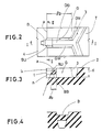
- the tread portion 2 is provided with circumferentially extending main grooves 3 and axially extending lateral grooves G to form an all season type tread pattern.
- the main grooves 3 extend in a zigzag shape in the circumferential direction of the tyre.
- the lateral grooves G extend from the angled portions of the zigzag main grooves 3 into the shoulder region 4 at a right angle to the circumferential direction of the tyre, and in this example, the axially outer end of the lateral groove G is open at the shoulder region, that is, the side face of the tyre.
- the lateral groove is provided with a bridge B formed between the opposed sidewalls GW of the lateral groove G and above the groove base GB.
- the bridge B is above the groove base GB and near the tread edge (a) between the tread region 2 and the shoulder regions 4 in the axial direction of the tyre.
- the stiffness of the groove sidewalls in the regions of the bridge B is increased and the amount of movement thereof is decreased. Therefore, slip against the ground is lessened on both sides of the lateral groove, the uneven wear of the tread is prevented.
- the bridge By forming the bridge near the tread edge (a), the movement of the sidewalls into the groove is effectively prevented at those points of the tyre.
- top of the above-mentioned bridge B is located beneath the tread face T so that a certain distance b is provided between the top face B/U of the bridge and the unworn or new tyre tread face T in the radial direction of the tyre, whereby good road grip is provided in the early stages of tyre life.
- the ratio b/d of the above-mentioned distance b to the groove depth d of the lateral groove from the tread face T to the groove base GB is in the range of 0 to 0.2.
- the ratio t/d of the thickness t of the bridge B in the radial direction to the groove depth d is not less than 0.1 and not more than 0.4.
- the radial distance h of the bottom face BB of the bridge from the groove base GB is not less than the thickness t of the bridge (t ⁇ h).
- the ratio lb/lg of the length lb of the bridge at the bottom face BB in the longitudinal direction of the lateral groove G to the length lg of the same lateral groove G in the longitudinal direction is not less than 0.05 and not more than 0.35.
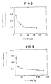
- test tyres mounted on 7.00T rims were installed on the front axle of a 2-2D wheel type pump truck and inflated to 8.0 kgf/sq.cm, and then the heel and toe wear was measured after 20,000 km running.
- the test reults are shown graphically in Figures 8 and 9.
- the ratio t/d of the thickness t of the bridge to the groove depth d is shown as the axis of abscissa and the heel and toe wear K measured as in Figure 21) is shown as the axis of ordinate.
- the radial distance h of the bottom face of the bridge from the groove base was 10.0mm
- the length lb of the bottom face in the longitudinal direction of the lateral groove was 8.0 mm
- the length lg of the lateral groove was 35 mm.
- the ratio lb/lg of the length lb of the bottom face of the bridge to the length lg of the lateral groove G is shown as the axis of abscissa and the heel and toe wear is shown as the axis of ordinate, where the ratio t/d is 0.3 and the thickness t is 0.8 times the distance h of the bottom face of the bridge.
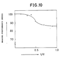
- Figure 10 shows the results of braking distance tests on a wet asphalt-paved road, in which the braking distance from 80km/h to a stop was measured.
- the ratio t/d and the wet braking performance are shown along the axis of abscissa and the axis of ordinate, respectively, wherein the wet braking performance is indicated in terms of an index based on the assumption that the braking distance in a tyre have no bridge is 100.
- the ratio t/d when the ratio t/d was set to be more than 0.4, the wet braking performance was decreased. If the ratio t/d is more than 0.4, the bridge becomes too thick, and it impedes the drainage of the groove and excessively restricts the movement of the groove sidewalls, both of which lessen the road grip. Accordingly, the ratio t/d is preferably set to be not more than 0.4 and further not less than 0.1.
- the radial height of h of the bottom BB of the bridge B from the groove base GB is less than t, the drainage of the lateral groove G is hindered, and the effect of the bridge B derived from connecting the groove sidewalls is diminished because the bridge B provides support to only the lower sidewalls of the groove.
- the ratio lb/lg of the length lb of the bottom face BB to the length lg of the lateral groove is less than 0.05, such a bridge cannot prevent the movement of the groove sidewalls and as a result, it becomes not possible to reduce the heel and toe wear K to be under 2.0mm. If the ratio is more than 0.35, it becomes too difficult to make the bridge using a vulcanizing mould. Accordingly, the ratio lb/lg is defined as being not less than 0.05 and not more than 0.35.
- the heel and toe wear can be reduced by means of the bridge B which connects the opposed groove sidewalls, and at the same time, the braking performance is maintained by setting the ratio t/d in the above specified range.
- the bridge B is gradually worn away during tyre use and finally disappears, and accordingly the lateral groove is then left fully opened which maintains the braking performance all through the tyre life.
- Figures 5 to 7 show another embodiment of the present invention, where the lateral groove G is formed in the tread crown region and extended between the adjacent two zig-zag main grooves 3, and the bridge B is formed in the centre of the lateral groove in the longitudinal direction of the groove.
- the lateral groove G can be arranged obliquely, and the top face B/U can be the same height as the tread face T.
- Figures 14 to 15 show another embodiment having a rib-lug type tread pattern, wherein the lateral groove G is provided at the groove base GB thereof with a deeper portion GB2 being deeper than the main portion GB1 so that the deeper portion is located beneath the bridge B.
- the depth at the deeper portion GB2 is used as the above-mentioned groove depth d to define the ratio t/d, but the length lg of the lateral groove G is defined as the total length lb including the main portion and the deeper portion. Accordingly, it then becomes possible to increase the thickness t of the bridge.
- Figures 16 to 18 show an all season type tread pattern in which the lateral groove G is provided with the deeper portion GB2 beneath the bridge B similarly to the previous embodiment.
- Figures 19 and 20 show a lug type tread pattern.
- the present invention can be applied to various kinds of tread patterns for various kinds of tyres such as heavy duty tyres for trucks and buses, passenger car tyres and so on.
- the opposed sidewalls of the lateral groove are connected with each other by the bridge, therefore the bridge can control the movement of the groove sidewalls when the tread contacts the ground and when it leaves the ground. Accordingly, abnormal wear such as heel and toe wear is prevented without deteriorating wet grip performance.
- such a bridge can be formed during or after the tyre vulcanising process.
- the bridges In order to form the bridges in the tyre vulcanising process, it is necessary to arrange the bridges to be near the positions of the split faces of the vulcanising mould. Therefore, the number of split faces and the position thereof may be adjusted to form the bridges at a desired position in the axial direction. Further, it may be necessary to limit the inclining angle of the lateral groove so that the demoulding process is possible.
- the bridge In order to form the bridge after the tyre vulcanising process, it is possible to drill or bore the lower part of the bridge. In this case, it is not necessary to limit the inclination angle of the lateral groove and therefore, the bridge can be formed in a lateral groove which is greatly inclined, for example, at 45 degrees.
Landscapes
- Engineering & Computer Science (AREA)
- Mechanical Engineering (AREA)
- Tires In General (AREA)
Applications Claiming Priority (2)
| Application Number | Priority Date | Filing Date | Title |
|---|---|---|---|
| JP63123428A JPH0257407A (ja) | 1988-05-19 | 1988-05-19 | 空気入りタイヤ |
| JP123428/88 | 1988-05-19 |
Publications (3)
| Publication Number | Publication Date |
|---|---|
| EP0342908A2 true EP0342908A2 (de) | 1989-11-23 |
| EP0342908A3 EP0342908A3 (en) | 1990-05-02 |
| EP0342908B1 EP0342908B1 (de) | 1993-06-23 |
Family
ID=14860323
Family Applications (1)
| Application Number | Title | Priority Date | Filing Date |
|---|---|---|---|
| EP89304904A Expired - Lifetime EP0342908B1 (de) | 1988-05-19 | 1989-05-16 | Luftreifen |
Country Status (4)
| Country | Link |
|---|---|
| US (1) | US5022448A (de) |
| EP (1) | EP0342908B1 (de) |
| JP (1) | JPH0257407A (de) |
| DE (1) | DE68907269T2 (de) |
Cited By (11)
| Publication number | Priority date | Publication date | Assignee | Title |
|---|---|---|---|---|
| EP0753419A3 (de) * | 1995-07-10 | 1997-07-02 | Sumitomo Rubber Ind | Reifenvulkanisierform, Luftreifen und Verfahren zu seiner Herstellung |
| WO1998035842A1 (fr) * | 1997-02-12 | 1998-08-20 | Companie Generale Des Etablissements Michelin - Michelin & Cie | Sculpture de bande de roulement et procede de fabrication |
| FR2772663A1 (fr) * | 1997-12-24 | 1999-06-25 | Michelin & Cie | Procede et element moulant pour mouler une decoupure dans une bande de roulement de pneumatique |
| DE19804338A1 (de) * | 1998-02-05 | 1999-08-19 | Continental Ag | Fahrzeugluftreifen |
| EP1034909A1 (de) * | 1999-03-10 | 2000-09-13 | Société de Technologie Michelin | Formelement und Formwerkzeug für eine Reifenlauffläche |
| EP1034908A1 (de) * | 1999-03-10 | 2000-09-13 | Société de Technologie Michelin | Formwerkzeugelement für Reifenlaufflächen |
| EP1034946A1 (de) * | 1999-03-10 | 2000-09-13 | Société de Technologie Michelin | Profil für Reifenlauffläche und Formwerkzeug dafür |
| US6378583B1 (en) | 2000-02-28 | 2002-04-30 | The Goodyear Tire & Rubber Company | Heel and toe wear balancing |
| EP1676693A1 (de) * | 2004-12-28 | 2006-07-05 | The Goodyear Tire & Rubber Company | Luftreifen mit einem verbesserten Steg |
| EP3584093A1 (de) * | 2018-06-18 | 2019-12-25 | Continental Reifen Deutschland GmbH | Fahrzeugluftreifen |
| KR20250012419A (ko) * | 2023-07-17 | 2025-01-24 | 한국타이어앤테크놀로지 주식회사 | 강성 및 배수 성능이 향상된 타이어 |
Families Citing this family (16)
| Publication number | Priority date | Publication date | Assignee | Title |
|---|---|---|---|---|
| FI944892L (fi) * | 1993-11-18 | 1995-08-18 | Bridgestone Corp | Pneumaattinen rengas |
| JP2774778B2 (ja) * | 1994-12-16 | 1998-07-09 | 住友ゴム工業株式会社 | 空気入りタイヤ |
| FR2759321B1 (fr) * | 1997-02-12 | 1999-03-19 | Michelin & Cie | Procede de fabrication et moule de bande de roulement |
| EP0968848B1 (de) * | 1998-07-03 | 2003-09-10 | Michelin Recherche et Technique S.A. | Reifenlauffläche mit Einschnitten ,welche Gummiblöcke begrenzen |
| JP4500491B2 (ja) * | 2001-01-29 | 2010-07-14 | ソシエテ ド テクノロジー ミシュラン | 転がり騒音を低減させるタイヤトレッド |
| US6631746B2 (en) | 2001-04-25 | 2003-10-14 | Bridgestone/Firestone North American Tire, Llc | Undercut tie bar for pneumatic tire |
| US6695024B2 (en) | 2001-08-03 | 2004-02-24 | Bridgestone/Firestone North American Tire, Llc | Pneumatic tire having tapered tie bars |
| FR2954221B1 (fr) * | 2009-12-17 | 2012-03-16 | Michelin Soc Tech | Pneu a performance de roulage amelioree |
| MX2013012707A (es) * | 2011-04-29 | 2013-12-09 | Michelin Rech Tech | Neumatico con banda de rodamiento que tiene areas punteadas con superficies de contacto divididas dentro de un surco lateral. |
| FR3014746B1 (fr) * | 2013-12-13 | 2017-08-11 | Michelin & Cie | Bande de roulement evolutive pour pneu. |
| JP2017501082A (ja) | 2013-12-26 | 2017-01-12 | ブリヂストン アメリカズ タイヤ オペレーションズ、 エルエルシー | 可撓性ゲート装置を有するタイヤトレッド |
| FR3029843A1 (fr) * | 2014-12-12 | 2016-06-17 | Michelin & Cie | Dispositif attenuateur de bruit en roulage pour pneu |
| BR112017013744A2 (pt) * | 2014-12-26 | 2019-02-05 | Michelin & Cie | banda de rodagem de pneu para redução de ruídos |
| US10821782B2 (en) | 2015-06-29 | 2020-11-03 | Compagnie Generale Des Etablissements Michelin | Tire tread for reducing noise |
| WO2018044305A1 (en) | 2016-08-31 | 2018-03-08 | Compagnie Generale Des Etablissements Michelin | Tire tread |
| FR3090480A3 (fr) * | 2018-12-21 | 2020-06-26 | Michelin & Cie | Bande de roulement comportant des cavités cachées et des rainures. |
Family Cites Families (6)
| Publication number | Priority date | Publication date | Assignee | Title |
|---|---|---|---|---|
| US2575439A (en) * | 1949-05-13 | 1951-11-20 | Goodrich Co B F | Tire |
| US2661041A (en) * | 1950-03-23 | 1953-12-01 | Armstrong Rubber Co | Tread construction for tire casings |
| GB1407790A (en) * | 1971-09-15 | 1975-09-24 | Dunlop Ltd | Tyres |
| AT344524B (de) * | 1976-08-10 | 1978-07-25 | Semperit Ag | Laufflaeche eines fahrzeugreifens |
| JPS61291205A (ja) * | 1985-06-20 | 1986-12-22 | Bridgestone Corp | サイプエツジの鮮鋭なタイヤトレツド |
| US4881881A (en) * | 1988-02-08 | 1989-11-21 | The Uniroyal Goodrich Tire Company | Plug-resistant arch-vents for a tire mold |
-
1988
- 1988-05-19 JP JP63123428A patent/JPH0257407A/ja active Pending
-
1989
- 1989-05-16 EP EP89304904A patent/EP0342908B1/de not_active Expired - Lifetime
- 1989-05-16 DE DE89304904T patent/DE68907269T2/de not_active Expired - Fee Related
- 1989-05-17 US US07/352,894 patent/US5022448A/en not_active Expired - Fee Related
Cited By (21)
| Publication number | Priority date | Publication date | Assignee | Title |
|---|---|---|---|---|
| EP0753419A3 (de) * | 1995-07-10 | 1997-07-02 | Sumitomo Rubber Ind | Reifenvulkanisierform, Luftreifen und Verfahren zu seiner Herstellung |
| US5800642A (en) * | 1995-07-10 | 1998-09-01 | Sumitomo Rubber Industries, Ltd. | Pneumatic tire, mold including vent grooves, and method |
| WO1998035842A1 (fr) * | 1997-02-12 | 1998-08-20 | Companie Generale Des Etablissements Michelin - Michelin & Cie | Sculpture de bande de roulement et procede de fabrication |
| KR100578266B1 (ko) * | 1997-02-12 | 2006-05-11 | 꽁빠니 제네랄 드 에따블리세망 미쉘린-미쉘린 에 씨 | 트레드 패턴 및 그 제조 방법 |
| AU735104B2 (en) * | 1997-02-12 | 2001-06-28 | Compagnie Generale Des Etablissements Michelin - Michelin & Cie | Tread pattern and method of manufacture |
| FR2772663A1 (fr) * | 1997-12-24 | 1999-06-25 | Michelin & Cie | Procede et element moulant pour mouler une decoupure dans une bande de roulement de pneumatique |
| EP0925907A1 (de) * | 1997-12-24 | 1999-06-30 | Compagnie Générale des Etablissements MICHELIN-MICHELIN & CIE | Verfahren zum Formen eines Ausschnittes in einer Reifenlauffläche und dabei verwendetes Formwerkzeug |
| US6143223A (en) * | 1997-12-24 | 2000-11-07 | Compagnie Generale Des Etablissements Michelin - Michelin & Cie | Process and molding element for molding a groove in a tire tread |
| DE19804338A1 (de) * | 1998-02-05 | 1999-08-19 | Continental Ag | Fahrzeugluftreifen |
| DE19804338C2 (de) * | 1998-02-05 | 2002-03-28 | Continental Ag | Fahrzeugluftreifen |
| FR2790701A1 (fr) * | 1999-03-10 | 2000-09-15 | Michelin Soc Tech | Element moulant et moule d'une bande de roulement de pneumatique |
| FR2790707A1 (fr) * | 1999-03-10 | 2000-09-15 | Michelin Soc Tech | Element moulant pour moule de bande de roulement de pneumatique |
| FR2790717A1 (fr) * | 1999-03-10 | 2000-09-15 | Michelin Soc Tech | Sculpture de bande de roulement et moule |
| EP1034946A1 (de) * | 1999-03-10 | 2000-09-13 | Société de Technologie Michelin | Profil für Reifenlauffläche und Formwerkzeug dafür |
| EP1034908A1 (de) * | 1999-03-10 | 2000-09-13 | Société de Technologie Michelin | Formwerkzeugelement für Reifenlaufflächen |
| EP1034909A1 (de) * | 1999-03-10 | 2000-09-13 | Société de Technologie Michelin | Formelement und Formwerkzeug für eine Reifenlauffläche |
| US6378583B1 (en) | 2000-02-28 | 2002-04-30 | The Goodyear Tire & Rubber Company | Heel and toe wear balancing |
| EP1676693A1 (de) * | 2004-12-28 | 2006-07-05 | The Goodyear Tire & Rubber Company | Luftreifen mit einem verbesserten Steg |
| US7276198B2 (en) | 2004-12-28 | 2007-10-02 | The Goodyear Tire & Rubber Company | Method and mold for making tire with tie bar |
| EP3584093A1 (de) * | 2018-06-18 | 2019-12-25 | Continental Reifen Deutschland GmbH | Fahrzeugluftreifen |
| KR20250012419A (ko) * | 2023-07-17 | 2025-01-24 | 한국타이어앤테크놀로지 주식회사 | 강성 및 배수 성능이 향상된 타이어 |
Also Published As
| Publication number | Publication date |
|---|---|
| DE68907269D1 (de) | 1993-07-29 |
| JPH0257407A (ja) | 1990-02-27 |
| US5022448A (en) | 1991-06-11 |
| DE68907269T2 (de) | 1993-09-30 |
| EP0342908A3 (en) | 1990-05-02 |
| EP0342908B1 (de) | 1993-06-23 |
Similar Documents
| Publication | Publication Date | Title |
|---|---|---|
| EP0342908B1 (de) | Luftreifen | |
| US6116309A (en) | Tread for a tire including five rib parts | |
| US6196288B1 (en) | Siping geometry to delay the onset of rib edge wear in truck tires | |
| US5361815A (en) | Tread for a tire with blocks and ribs | |
| EP0904960B1 (de) | Spikeloser luftreifen | |
| EP0178859B1 (de) | Radialreifen für Lastkraftwagen | |
| EP0829381B1 (de) | Reifen und Vulkanisationsform dazu | |
| US4320790A (en) | Tire treads | |
| US6102093A (en) | Pneumatic tire including long blocks and wide blocks | |
| JP2002538030A (ja) | 犠牲ブリッジングを有するタイヤ | |
| CA2004644A1 (en) | Heavy duty pneumatic tires | |
| EP1676727B1 (de) | Reifenlauffläche mit hinterschnittenen Profilelementen | |
| JP2007153338A (ja) | 大型車用タイヤのトレッド | |
| EP0787600B1 (de) | Reifen mit guten verschiedenen Eigenschaften | |
| JPS62103205A (ja) | 重荷重用空気入りタイヤ | |
| CA1126141A (en) | Large-sized pneumatic radial tires | |
| JPH09188110A (ja) | 重荷重用空気入りラジアルタイヤ | |
| JPH07186626A (ja) | 空気入りラジアルタイヤ | |
| CN112423997B (zh) | 用于车辆车轮的嵌钉轮胎 | |
| EP3814151B1 (de) | Lauffläche für verbessertes schneeverhalten | |
| JPH04138902A (ja) | 重荷重用空気入りスタッドレスタイヤ | |
| JPH0440204B2 (de) | ||
| AU649554B2 (en) | A tread for a tire | |
| JPH07223409A (ja) | 重荷重用空気入りタイヤ | |
| JP2755353B2 (ja) | 重荷重用タイヤ |
Legal Events
| Date | Code | Title | Description |
|---|---|---|---|
| PUAI | Public reference made under article 153(3) epc to a published international application that has entered the european phase |
Free format text: ORIGINAL CODE: 0009012 |
|
| AK | Designated contracting states |
Kind code of ref document: A2 Designated state(s): DE FR GB |
|
| PUAL | Search report despatched |
Free format text: ORIGINAL CODE: 0009013 |
|
| AK | Designated contracting states |
Kind code of ref document: A3 Designated state(s): DE FR GB |
|
| 17P | Request for examination filed |
Effective date: 19901012 |
|
| 17Q | First examination report despatched |
Effective date: 19920511 |
|
| GRAA | (expected) grant |
Free format text: ORIGINAL CODE: 0009210 |
|
| AK | Designated contracting states |
Kind code of ref document: B1 Designated state(s): DE FR GB |
|
| REF | Corresponds to: |
Ref document number: 68907269 Country of ref document: DE Date of ref document: 19930729 |
|
| ET | Fr: translation filed | ||
| PLBE | No opposition filed within time limit |
Free format text: ORIGINAL CODE: 0009261 |
|
| STAA | Information on the status of an ep patent application or granted ep patent |
Free format text: STATUS: NO OPPOSITION FILED WITHIN TIME LIMIT |
|
| 26N | No opposition filed | ||
| PGFP | Annual fee paid to national office [announced via postgrant information from national office to epo] |
Ref country code: GB Payment date: 19970507 Year of fee payment: 9 |
|
| PGFP | Annual fee paid to national office [announced via postgrant information from national office to epo] |
Ref country code: FR Payment date: 19970513 Year of fee payment: 9 |
|
| PGFP | Annual fee paid to national office [announced via postgrant information from national office to epo] |
Ref country code: DE Payment date: 19970523 Year of fee payment: 9 |
|
| PG25 | Lapsed in a contracting state [announced via postgrant information from national office to epo] |
Ref country code: GB Free format text: LAPSE BECAUSE OF NON-PAYMENT OF DUE FEES Effective date: 19980516 |
|
| PG25 | Lapsed in a contracting state [announced via postgrant information from national office to epo] |
Ref country code: FR Free format text: LAPSE BECAUSE OF NON-PAYMENT OF DUE FEES Effective date: 19980531 |
|
| GBPC | Gb: european patent ceased through non-payment of renewal fee |
Effective date: 19980516 |
|
| PG25 | Lapsed in a contracting state [announced via postgrant information from national office to epo] |
Ref country code: DE Free format text: LAPSE BECAUSE OF NON-PAYMENT OF DUE FEES Effective date: 19990302 |
|
| REG | Reference to a national code |
Ref country code: FR Ref legal event code: ST |