EP0342773A2 - Verfahren und Vorrichtung zum Ausbalancieren von Reifen durch Schleifen - Google Patents
Verfahren und Vorrichtung zum Ausbalancieren von Reifen durch Schleifen Download PDFInfo
- Publication number
- EP0342773A2 EP0342773A2 EP89300197A EP89300197A EP0342773A2 EP 0342773 A2 EP0342773 A2 EP 0342773A2 EP 89300197 A EP89300197 A EP 89300197A EP 89300197 A EP89300197 A EP 89300197A EP 0342773 A2 EP0342773 A2 EP 0342773A2
- Authority
- EP
- European Patent Office
- Prior art keywords
- tire
- cutting
- cutting device
- tread
- circumference
- Prior art date
- Legal status (The legal status is an assumption and is not a legal conclusion. Google has not performed a legal analysis and makes no representation as to the accuracy of the status listed.)
- Granted
Links
Images


Classifications
-
- B—PERFORMING OPERATIONS; TRANSPORTING
- B29—WORKING OF PLASTICS; WORKING OF SUBSTANCES IN A PLASTIC STATE IN GENERAL
- B29D—PRODUCING PARTICULAR ARTICLES FROM PLASTICS OR FROM SUBSTANCES IN A PLASTIC STATE
- B29D30/00—Producing pneumatic or solid tyres or parts thereof
- B29D30/06—Pneumatic tyres or parts thereof (e.g. produced by casting, moulding, compression moulding, injection moulding, centrifugal casting)
- B29D30/52—Unvulcanised treads, e.g. on used tyres; Retreading
- B29D30/68—Cutting profiles into the treads of tyres
-
- G—PHYSICS
- G01—MEASURING; TESTING
- G01M—TESTING STATIC OR DYNAMIC BALANCE OF MACHINES OR STRUCTURES; TESTING OF STRUCTURES OR APPARATUS, NOT OTHERWISE PROVIDED FOR
- G01M17/00—Testing of vehicles
- G01M17/007—Wheeled or endless-tracked vehicles
- G01M17/02—Tyres
- G01M17/022—Tyres the tyre co-operating with rotatable rolls
- G01M17/024—Tyres the tyre co-operating with rotatable rolls combined with tyre surface correcting or marking means
-
- Y—GENERAL TAGGING OF NEW TECHNOLOGICAL DEVELOPMENTS; GENERAL TAGGING OF CROSS-SECTIONAL TECHNOLOGIES SPANNING OVER SEVERAL SECTIONS OF THE IPC; TECHNICAL SUBJECTS COVERED BY FORMER USPC CROSS-REFERENCE ART COLLECTIONS [XRACs] AND DIGESTS
- Y10—TECHNICAL SUBJECTS COVERED BY FORMER USPC
- Y10S—TECHNICAL SUBJECTS COVERED BY FORMER USPC CROSS-REFERENCE ART COLLECTIONS [XRACs] AND DIGESTS
- Y10S451/00—Abrading
- Y10S451/92—Tyre "rounding"
-
- Y—GENERAL TAGGING OF NEW TECHNOLOGICAL DEVELOPMENTS; GENERAL TAGGING OF CROSS-SECTIONAL TECHNOLOGIES SPANNING OVER SEVERAL SECTIONS OF THE IPC; TECHNICAL SUBJECTS COVERED BY FORMER USPC CROSS-REFERENCE ART COLLECTIONS [XRACs] AND DIGESTS
- Y10—TECHNICAL SUBJECTS COVERED BY FORMER USPC
- Y10T—TECHNICAL SUBJECTS COVERED BY FORMER US CLASSIFICATION
- Y10T409/00—Gear cutting, milling, or planing
- Y10T409/30—Milling
- Y10T409/304536—Milling including means to infeed work to cutter
- Y10T409/305544—Milling including means to infeed work to cutter with work holder
- Y10T409/305656—Milling including means to infeed work to cutter with work holder including means to support work for rotation during operation
- Y10T409/305712—Milling including means to infeed work to cutter with work holder including means to support work for rotation during operation and including means to infeed cutter toward work axis
-
- Y—GENERAL TAGGING OF NEW TECHNOLOGICAL DEVELOPMENTS; GENERAL TAGGING OF CROSS-SECTIONAL TECHNOLOGIES SPANNING OVER SEVERAL SECTIONS OF THE IPC; TECHNICAL SUBJECTS COVERED BY FORMER USPC CROSS-REFERENCE ART COLLECTIONS [XRACs] AND DIGESTS
- Y10—TECHNICAL SUBJECTS COVERED BY FORMER USPC
- Y10T—TECHNICAL SUBJECTS COVERED BY FORMER US CLASSIFICATION
- Y10T82/00—Turning
- Y10T82/10—Process of turning
-
- Y—GENERAL TAGGING OF NEW TECHNOLOGICAL DEVELOPMENTS; GENERAL TAGGING OF CROSS-SECTIONAL TECHNOLOGIES SPANNING OVER SEVERAL SECTIONS OF THE IPC; TECHNICAL SUBJECTS COVERED BY FORMER USPC CROSS-REFERENCE ART COLLECTIONS [XRACs] AND DIGESTS
- Y10—TECHNICAL SUBJECTS COVERED BY FORMER USPC
- Y10T—TECHNICAL SUBJECTS COVERED BY FORMER US CLASSIFICATION
- Y10T82/00—Turning
- Y10T82/25—Lathe
- Y10T82/2502—Lathe with program control
Definitions
- This invention relates to an improved apparatus and method for removing selected portions of material from a tire surface while the tire is rotating.
- the invention is particularly applicable to grinding the tread surface of a tire to improve its force variation characteristics, and may also be used to improve the tire's run-out, or out-of-roundness characteristic, as well as its conicity.
- the portions of the circumference where the force transmitted between the tire and the load drum is excessively high in relation to other portions may be corrected by removing rubber from the tire tread. This rubber removal reduces the tire's stiffness in these portions and consequently reduces the amount of force transmitted to levels closer to the force transmitted in other areas.
- additional rubbery material is applied to the tread surface in areas of low force transmission instead of being removed in areas where the force is high.
- hydraulic pistons are used to move the grinding wheels into and out of engagement with the tread rubber.
- the pistons locate the grinding wheels at the desired cutting depths and are moved by pressurized hydraulic fluid.
- the fluid is controlled by a servo system that is designed to move the pistons and grinding wheels to their correct grinding positions.
- the pressurized fluid pushes the grinding wheels in one direction, the tire being buffed pushes back on the grinding wheels; so the exact positioning of the pistons and grinding wheels is determined by a balancing of the pressure in the hydraulic system to position the grind wheel.
- the pistons can be delayed and can oscillate as they travel to their full cutting depth during this hydraulic pressure/tire force balancing.
- one problem with using hydraulic pistons to locate the grinding wheels is that the wheels cannot be set at accurately fixed, predetermined cutting depths at the exact locations of the tire circumference where rubber removal is desired.
- a positioning means is designed to hold a cutting device in a fixed, accurately determined position relative to the tire surface for a predetermined increment of distance and is also designed to be varied during successive intervals corresponding to successive increments of the tire circumference.
- a computing device receives electrical signals representative of circumferential variations in a characteristic of the tire, and determines, based on these signals, the placement of the cutting device relative to the tire surface for each distance interval corresponding to an increment of the tire circumference.
- the computing device is connected to the positioning means and controls the positioning means to locate the cutting device at its proper location in each increment of the tire circumference, so as to remove the desired amount of material from each of these increments.
- a load wheel is movable into loaded engagement with the tread surface of the tire, and a load cell measures the variations in force transmitted between the tire and the load wheel.
- the electric signal generating means generates signals proportional to the force variations and the cutting device is in the form of a grinding wheel which removes rubber from the tire to reduce the force variations.
- force variations in a tire are reduced by measuring the magnitudes and locations of the force variations, and calculating from these measurements the depth of cutting required in each of a plurality of increments of the tire circumference.
- the radial run-out of the tire is also measured, and in response to the run-out measurements and cutting depth calculations, a cutting device is moved into engagement with the rotating tire at the calculated cutting depth relative to the run-out measurement at each increment of the tire circumference.
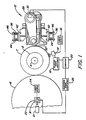
- a tire T is mounted and inflated on a rim.
- a variable speed motor 4 rotates the tire T about its axis.
- the tire T is shown under load provided by a load wheel 6, rotatably supported on bearing blocks 8 on either side of the wheel.
- the blocks 8 are movable by electric motors 10 which operate by a ball-and-screw connection to bring the wheel 6 into and out of engagement with the tire T.
- a tire grinding apparatus 12 is located on the opposite side of tire T from load wheel 6.
- a radial run-out transducer 14 is positioned on the surface of the tire T for sensing the variations in the tread diameter around the tire's circumference.
- the transducer 14 receives power from power source 16 and feeds the run-out signal through a signal conditioner 18 to a computer 20.
- a load cell 22 is mounted on the axle of load wheel 6 to measure the force transmitted to the tire T as it rotates against the wheel 6.
- a power source 24 and electric signal conditioner 26 transform the force measurements sensed by the load cell 22 into electric signals which can be received and stored in the computer 20.
- the computer 20 stores the electric signals received from the signal conditioner 26, assigning a force value to each of a large number of increments of the tire circumference. Preferably, there are at least 100 such increments should be of equal length.
- the computer is programmed to determine whether the differences in the force values of the various increments are below the chosen maximum limits beyond which it is not desirable to try to correct the tire. If the tire passes this test, the computer determines how much rubber must be removed from the tread increments having the force values that are too high. These calculations are made using a multiplier factor based on what previous experience with the tire being corrected indicates is the correct depth of cut required to reduce by a certain amount the force transmitted by the tire. This is the type of correction one would use to reduce the composite force variation of the tire.
- the first harmonic component and/or other harmonic components of the composite force variation pattern may be calculated and the increments to be ground and grinding depths in each increment may be based on the peaks occurring in one or more of these component patterns.
- the computer can be programmed to make these calculations using mathematical relationships well known in the art.
- the computer After the computer calculates the total depth of grinding required for each increment of the tread circumference, it sets the grinding depth at which rubber is to be removed from each increment during each revolution of the tire, according to a preset formula designed to remove relatively large amounts of rubber at the beginning of the grinding and to use smaller finishing cuts near the completion of the grinding.
- the computer combines these chosen grinding depths with the radial run-out values for each increment being ground to determine where the carriages holding the grinding wheels must be placed to grind the increments at their chosen depths. Based on this information, the computer sends commands to stepper motors 28 and 30 mounted on the apparatus 12 and shown in Figure 3, to position grinding wheels 32 ( Figures 1, 2 and 3) and 34 ( Figure 3) in their desired grinding location for each increment of the tire tread passing by them.
- the grinding apparatus 12 is supported on column members 36 ( Figures 1, 2 and 3).
- vertical plates 38 and 40 are welded to plates 42 on the inside of each column to form supporting brackets that are held on the column 36 by bolts 44 and plates 46 on the outsides of the columns.
- Vertical dove tail rails 48 attached to the plates 40 form tracks on which supports 50 and 52 may be independently raised and lowered.
- the bearing support 50 may be raised and lowered by turning screw 54, which is rotatably held by a bracket 56 connected to plate 40 and threadably engage a collar 58 on bearing support 50.
- the screw 54 is powered by a stepper motor 59.
- screw 60 powered by a stepper motor 61 may be turned to raise and lower bearing support 52.
- This adjustment of the bearing supports 50 and 52 allows the grinding wheels 32 and 34 to be spaced at different distances apart to accommodate the grinding of different sizes of tires.
- Horizontal frame members 62 and 64 are rotatably mounted on bearing supports 50 and 52 by means of trunions mounted in roller bearings.
- the trunion 66 and roller bearings 68 mounted on frame member 62 are shown in the partial section of bearing support 50 of Figure 2.
- the frame members 62 and 64 may be rotated about their trunions by turning screws 70 and 72, rotatably mounted by brackets 74 and 76 on the sides of bearing supports 50 and 52.
- the screw 70 threadably engages a collar 78 connected to the tube 80.
- the screw 70 is powered by a stepper motor 81. By turning the screw 70, the tube 80 may be raised or lowered to raise or lower arm 82 fixed to the top of the tube 80.
- a link 84 connects the arm 82 to a pin 86 extending from the side of frame member 64, so that through this linkage, the turning of the screw 70 rotates the frame member 64 about the trunion 66.
- screw 72 powered by a stepper motor 87, may be turned to move arm 88 and connected link 90 which is attached by pin 92 to frame member 64, thus rotating the member 64 about its horizontal trunion, which is not shown in the drawings.
- the rotation of the horizontal frame member 62 and 64 makes possible the setting of the grinding wheels 32 and 34 at different angles to the centerplane of the tire, so that tires of different tread profiles may be corrected.
- the frame members 62 and 64 each support two round rails 94 and 96 respectively, fastened to the members 62 and 64 by brackets 98 and 100 respectively.
- Carriage 102 supporting grind wheel 32 is mounted on upper rail 94 by means of a slide bearing 104 and on the lower rail 94 by means of a bracket 105.
- Carriage 106 supporting grind wheel 34 is mounted on lower rail 96 by means of a slide bearing 108 ( Figure 3) and on the upper rail 96 by means of a bracket 109.
- bellows 110 cover the rails 94 for protection, and they are mounted between the brackets 98 and slide bearings 104.
- Bellows 112 between brackets 100 and slide bearings 108 protect the rails 96.
- the carriages 102 and 106 are driven along rails 94 and 96 by stepper motors 28 and 30, mounted on frame members 62 and 64 by brackets 114 and 116 respectively.
- the stepper motors 28 and 30 drive threaded shafts 118 and 120, which engage brackets 105 and 109 to advance or pull back the carriages 102 and 106 to position their respective grinding wheels 32 and 34.
- the stepper motors 28 and 30 are provided with stop means that enables them to turn the shafts 118 and 120 by precise amounts in response to coded commands.
- the drive system for the grinding wheels is illustrated in Figure 5 for the grind wheel 34.
- An electric motor 122 mounted on the carriage 106 drives a pulley 124.
- the grind wheel 34 is fixed to a shaft 126 which is in turn rotatably mounted by ball bearings 128 on the carriage 106.
- a pulley 130 on the shaft 126 is connected by an endless belt 132 to the motor driven pulley 124.
- the motor 122 drives the grinding wheel 34 within its protective housing 134.
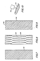
- Figures 7 and 8 illustrate several grinding wheels 136 and 138 having two types of recommended cutting surfaces.
- the wheel 136 has spiral cutting edges which shave off the rubber from the tire much like a milling cutter machines a metal surface.
- the wheel 138 has cutting surfaces that function in a similar manner, but they are arranged in converging relationships to provide elongated separate cutting ridges 140.
- Figure 9 shows a grinding wheel 142 that has a contoured surface (143) to more closely match the shoulder ribs of a typical radial tire, in order to grind the tread more uniformly and over a wider surface area.
- Figure 10 illustrates a run-out transducer 14a that is especially designed for measuring the run-out of tires having wide lateral grooves.
- the transducer is equipped with an elongated curved plate 144 that is designed to bridge the gap between such lateral grooves, so that the transducer will not be subject to sudden impulses by a shorter plate hitting the walls of the grooves.
- the tire is conveyed to a check point (148) at an inlet gate.
- the inlet gate opens (150) and the tire is centered over a chuck (152).
- the chuck moves up to seat the tire on the test rim (154), and the tire is inflated to seat the beads (156).
- the tire is pressurized to its inflation test pressure (158) which for most passenger tires is recommended at 30 PSI.
- the motor 10 is operated to move the load wheel 6 into engagement with the tire (160), and one or more run-out probes 14 are moved into their measuring positions on the tread surface (162).
- the run-out of the tire is received by the computer 20, which commands the stepper motors 28 and 30 to advance the grind wheels 32 and 34 to their "ready" position, (164) spaced a short fixed distance from the tire tread and tracking the tread surface according to the run-out measurement taken by the run-out probes 14.
- the tire is run in a clockwise direction at 60 RPM to take another reading of the run-out and also the measure of the force variation pattern of the tire (168).
- the run-out and force variation signals produce by the run-out and force variation signal conditioners 18 and 26 are digitized by the computer, by assigning a value for each measurement to each of 100 equal increments of the tire circumference (170).
- the run-out variations are compared with pre-set limits to determine whether the run-out should be corrected (172). If the run-out is not within these limits, it is checked to determine if it is within maximum limits for making it worthwhile to correct the tire (174) ( Figure 12).
- the run-out and force correction steps are by-passed and the grinding wheels and run-out probes are retracted (176). If the run-out variation is below the limits making correction worthwhile, the motors 28 and 30 advance the grinding wheels 32 and 34 to the proper grind depths in the increments where the run-out is too high (178). After grinding to correct the run-out, the run-out is again checked to determine whether it is now below the limits compared in step (172). If not, the amount of time spent on run-out grinding is compared with a maximum grind time, so that too much time is not taken grinding a tire that is difficult to correct for run-out (182). If there is still time remaining on the grinding clock, the run-out grinding step (178) is repeated.
- the variations in the tire's force values for the various circumferential increments are compared with the acceptable force variation limits (184) ( Figure 1). If the force variation is acceptable the force correction steps are by-passed and the grinding wheels and run-out probes are retracted (176). If the force variation is not acceptable, the variation is compared with maximum values above which it is considered not worthwhile to correct the tire (186) ( Figure 13). If the force variation is above these maximum values, the correction is terminated and the grinding wheels and run-out probes are retracted (176) ( Figure 11).
- the speed of the motor 4 rotating the tire T ( Figure 1) is reduced to an optimum speed below 60 RPM for force variation correcting the tire (188) and the required grinding depths are calculated by the computer 20 (190).
- the computer 20 uses these grinding depths to position the grinding wheels in their proper positions for reducing the force values in each increment of the tire circumference that needs correction (192).
- the force variation values are continuously monitored by the computer 20 (194), and if the grinding depths need to be reset (196) and the depths which are needed for correction are below the maximum permissible depths for grinding (198) the grinding depths are reset (200) and the grinding to correct the force variation (192) continues.
- the tire speed is increased back to 60 RPM (202) and the force variation is checked at this higher speed (204).
- the grinding wheels 32 and 34 and run-out probes 14 are retracted (176).
- the computer calculates the location of the peak of the first harmonic of the force variation pattern of the corrected tire and a marking device marks the tire at these point (206).
- the motor 4 then reverses the direction of rotation of the tire (208) and tests the force variation of the tire at 60 RPM in the counter-clockwise direction (210).
- the first, harmonic peak of this force variation pattern is also marked on the tire (212) and then the speed of the tire is reduced until the tire stops rotating (214).
- the motor 10 retracts the load wheel (216), the tire is deflated (218), removed from its chuck (220 and 222) and conveyed to a marking station (224) for tire grade marking (225).
- the tire is then conveyed through an exit gate (228) for appropriate disposition according to the grade it receives.
Landscapes
- Physics & Mathematics (AREA)
- General Physics & Mathematics (AREA)
- Engineering & Computer Science (AREA)
- Mechanical Engineering (AREA)
- Testing Of Balance (AREA)
- Tyre Moulding (AREA)
- Grinding Of Cylindrical And Plane Surfaces (AREA)
Applications Claiming Priority (2)
| Application Number | Priority Date | Filing Date | Title |
|---|---|---|---|
| US07/194,652 US4914869A (en) | 1988-05-16 | 1988-05-16 | Method for correcting and buffing tires |
| US194652 | 1988-05-16 |
Publications (3)
| Publication Number | Publication Date |
|---|---|
| EP0342773A2 true EP0342773A2 (de) | 1989-11-23 |
| EP0342773A3 EP0342773A3 (en) | 1990-08-01 |
| EP0342773B1 EP0342773B1 (de) | 1993-07-28 |
Family
ID=22718398
Family Applications (1)
| Application Number | Title | Priority Date | Filing Date |
|---|---|---|---|
| EP89300197A Expired - Lifetime EP0342773B1 (de) | 1988-05-16 | 1989-01-11 | Verfahren und Vorrichtung zum Ausbalancieren von Reifen durch Schleifen |
Country Status (11)
| Country | Link |
|---|---|
| US (1) | US4914869A (de) |
| EP (1) | EP0342773B1 (de) |
| JP (1) | JPH0641188B2 (de) |
| KR (1) | KR0129543B1 (de) |
| AR (1) | AR240418A1 (de) |
| CA (1) | CA1323197C (de) |
| DE (1) | DE68907790T2 (de) |
| ES (1) | ES2044074T3 (de) |
| MA (1) | MA21541A1 (de) |
| MX (1) | MX164936B (de) |
| PT (1) | PT90539B (de) |
Cited By (6)
| Publication number | Priority date | Publication date | Assignee | Title |
|---|---|---|---|---|
| EP0556017A1 (de) * | 1992-02-10 | 1993-08-18 | General Tire, Inc. | Verfahren zum Korrigieren der lateralen Kraftschwankungen eines Luftreifens |
| WO1998004897A1 (en) * | 1996-07-30 | 1998-02-05 | The Goodyear Tire & Rubber Company | Method of enhancing the measurement accuracy of a tire uniformity machine |
| WO1998005937A1 (en) * | 1996-08-02 | 1998-02-12 | The Goodyear Tire & Rubber Company | Method of high speed centrifugal run-out grinding of a pneumatic tire |
| US6035709A (en) * | 1996-07-30 | 2000-03-14 | The Goodyear Tire & Rubber Company | Method of enhancing the measurement accuracy of a tire uniformity machine |
| US6086452A (en) * | 1996-08-02 | 2000-07-11 | The Goodyear Tire & Rubber Company | Method of high speed centrifugal run-out grinding of a pneumatic tire |
| CN111929081A (zh) * | 2020-07-31 | 2020-11-13 | 济宁齐鲁检测技术有限公司 | 一种载重汽车轮胎胎圈耐久性能试验方法 |
Families Citing this family (27)
| Publication number | Priority date | Publication date | Assignee | Title |
|---|---|---|---|---|
| WO1993022736A1 (en) * | 1992-05-01 | 1993-11-11 | Zev Galel | Autonomous selective cutting, method and apparatus |
| US5263284A (en) * | 1992-11-20 | 1993-11-23 | General Tire, Inc. | Method of simultaneously correcting excessive radial force variations and excessive lateral force variations in a pneumatic tire |
| US5645465A (en) * | 1995-09-27 | 1997-07-08 | The Goodyear Tire & Rubber Company | Method of correcting conicity, radial run out, and force variations in a pneumatic tire |
| US5614676A (en) * | 1996-03-08 | 1997-03-25 | The Goodyear Tire & Rubber Company | Method of machine vibration analysis for tire uniformity machine |
| US6386945B1 (en) | 1996-09-20 | 2002-05-14 | The Goodyear Tire & Rubber Company | Method of correcting conicity in a tire with a feedback loop |
| US6139401A (en) * | 1996-10-15 | 2000-10-31 | The Goodyear Tire & Rubber Company | Method of correcting the imbalance of a pneumatic tire with a tire uniformity machine |
| GB2333481B (en) * | 1996-10-15 | 2001-03-07 | Goodyear Tire & Rubber | Method of correcting the imbalance of a pneumatic tire with a tire uniformity machine |
| US6405146B1 (en) | 1996-12-30 | 2002-06-11 | The Goodyear Tire & Rubber Company | Method of adaptive warm-up of force variation machine |
| US6257956B1 (en) | 2000-03-06 | 2001-07-10 | The Goodyear Tire & Rubber Company | Method to identify and remove machine contributions from tire uniformity measurements |
| US6584836B1 (en) | 2001-12-10 | 2003-07-01 | The Goodyear Tire & Rubber Company | Bias method for identifying and removing machine contribution to test data |
| AU2006200179B2 (en) * | 2002-04-22 | 2006-09-21 | Micro-Poise Measurement Systems, Llc | Improvements in tire uniformity testing |
| US6915684B2 (en) * | 2002-04-22 | 2005-07-12 | Illinois Tool Works, Inc. | Tire uniformity testing |
| US6718818B2 (en) | 2002-07-19 | 2004-04-13 | The Goodyear Tire & Rubber Company | Method of sensing air leaks in tires and tire testing machines |
| US6688168B1 (en) * | 2002-11-19 | 2004-02-10 | Delphi Technologies, Inc. | Method for determining axle load of a moving vehicle |
| JP2005087976A (ja) * | 2003-09-19 | 2005-04-07 | National Institute Of Advanced Industrial & Technology | 研削によるゴム粉の製造方法及び装置 |
| US9011203B2 (en) | 2007-03-29 | 2015-04-21 | Michelin Recherche Et Technique S.A. | Retread tire buffing with multiple response curves |
| US8357026B2 (en) * | 2007-03-29 | 2013-01-22 | Michelin Recherche Et Technique S.A. | Retread tire buffing with multiple response curves |
| BRPI0721804A2 (pt) * | 2007-06-28 | 2013-05-21 | Michelin Soc Tech | mÉtodo para corrigir um desbaste da banda de rodagem de uma coroa de um pneu, e, mÁquina de desbaste de pneu |
| BRPI0721856A2 (pt) * | 2007-06-28 | 2013-04-02 | Michelin Soc Tech | mÉtodo para determinar um raio de desbaste para desbastar a banda de rodagem de uma coroa de um pneu, e, mÁquina de desbaste de pneu |
| CA2690812C (en) * | 2007-06-29 | 2013-01-08 | Michelin Recherche Et Technique S.A. | Tire buffing debris collection system |
| WO2009041980A1 (en) * | 2007-09-28 | 2009-04-02 | Societe De Technologie Michelin | Correction of crown layer variance during retreading |
| US8585843B2 (en) * | 2010-03-08 | 2013-11-19 | Bridgestone Bandag, Llc | Tire tread buffing apparatus and method |
| WO2012074517A1 (en) * | 2010-11-30 | 2012-06-07 | Michelin Recherche Et Technique S.A. | Profiled plane abrading tool for tire repairs |
| CN106247880A (zh) * | 2016-08-11 | 2016-12-21 | 上海大学 | 一种砂轮径向全跳动检测装置 |
| WO2019005529A1 (en) * | 2017-06-30 | 2019-01-03 | Bridgestone Americas Tire Operations, Llc | ENCLOSURE SYSTEM FOR TIRE TEST INDOOR |
| CN109332903B (zh) * | 2018-08-30 | 2024-03-22 | 珠海格力电器股份有限公司 | 贯流风叶矫正装置和矫正方法 |
| CN113021861B (zh) * | 2021-03-24 | 2022-12-27 | 山东省三利轮胎制造有限公司 | 一种轮胎胎纹的成型设备 |
Family Cites Families (15)
| Publication number | Priority date | Publication date | Assignee | Title |
|---|---|---|---|---|
| CA1025695A (en) * | 1967-02-01 | 1978-02-07 | Clarence Hofelt (Jr.) | Means for correcting non-uniformity in tires |
| US3724137A (en) * | 1967-02-01 | 1973-04-03 | Gen Tire & Rubber Co | Means for correcting non-uniformity in tires |
| US3553903A (en) * | 1967-07-31 | 1971-01-12 | Goodyear Tire & Rubber | Control system for a tire grinding machine |
| US3754358A (en) * | 1969-08-12 | 1973-08-28 | Goodrich Co B F | Method for correcting non-uniformity in a rotating tire |
| JPS512157B1 (de) * | 1970-09-25 | 1976-01-23 | ||
| JPS5140105B1 (de) * | 1971-07-06 | 1976-11-01 | ||
| US3841033A (en) * | 1972-06-27 | 1974-10-15 | Goodyear Tire & Rubber | Tire manufacturing |
| US3818642A (en) * | 1972-10-03 | 1974-06-25 | Babcock & Wilcox Co | Grinding machine |
| US3841034A (en) * | 1972-11-10 | 1974-10-15 | G Held | Tread grinding wheel |
| DE2456835A1 (de) * | 1973-12-03 | 1976-01-02 | Fabricated Machine Co | Vorrichtung zur korrektur von fehlern in der gleichfoermigkeit und im rundlauf bei fahrzeugreifen |
| US4041647A (en) * | 1974-07-26 | 1977-08-16 | Uniroyal, Inc. | Apparatus for improving tire uniformity |
| US4084350A (en) * | 1974-11-18 | 1978-04-18 | Ongaro Dynamics, Ltd. | Correction of rubber tires for forces generated by dynamic non-uniformities |
| US4112630A (en) * | 1977-08-08 | 1978-09-12 | The Goodyear Tire & Rubber Company | Reduction of lateral force variations of a tire effective in both forward and rearward senses of rotation |
| US4458451A (en) * | 1981-12-31 | 1984-07-10 | The B. F. Goodrich Company | Tire uniformity machine |
| US4837980A (en) * | 1987-07-01 | 1989-06-13 | The Uniroyal Goodrich Tire Company | Method and apparatus for tire uniformity correction |
-
1988
- 1988-05-16 US US07/194,652 patent/US4914869A/en not_active Expired - Fee Related
-
1989
- 1989-01-09 CA CA000587762A patent/CA1323197C/en not_active Expired - Fee Related
- 1989-01-11 EP EP89300197A patent/EP0342773B1/de not_active Expired - Lifetime
- 1989-01-11 DE DE89300197T patent/DE68907790T2/de not_active Expired - Fee Related
- 1989-01-11 ES ES89300197T patent/ES2044074T3/es not_active Expired - Lifetime
- 1989-01-31 AR AR313115A patent/AR240418A1/es active
- 1989-01-31 MX MX14716A patent/MX164936B/es unknown
- 1989-03-20 KR KR1019890003462A patent/KR0129543B1/ko not_active Expired - Fee Related
- 1989-04-19 MA MA21790A patent/MA21541A1/fr unknown
- 1989-05-12 JP JP1117624A patent/JPH0641188B2/ja not_active Expired - Lifetime
- 1989-05-12 PT PT90539A patent/PT90539B/pt not_active IP Right Cessation
Cited By (9)
| Publication number | Priority date | Publication date | Assignee | Title |
|---|---|---|---|---|
| EP0556017A1 (de) * | 1992-02-10 | 1993-08-18 | General Tire, Inc. | Verfahren zum Korrigieren der lateralen Kraftschwankungen eines Luftreifens |
| WO1998004897A1 (en) * | 1996-07-30 | 1998-02-05 | The Goodyear Tire & Rubber Company | Method of enhancing the measurement accuracy of a tire uniformity machine |
| US6035709A (en) * | 1996-07-30 | 2000-03-14 | The Goodyear Tire & Rubber Company | Method of enhancing the measurement accuracy of a tire uniformity machine |
| WO1998005937A1 (en) * | 1996-08-02 | 1998-02-12 | The Goodyear Tire & Rubber Company | Method of high speed centrifugal run-out grinding of a pneumatic tire |
| GB2333731A (en) * | 1996-08-02 | 1999-08-04 | Goodyear Tire & Rubber | Method of high speed centrifugal run-out grinding of a pneumatic tire |
| US6086452A (en) * | 1996-08-02 | 2000-07-11 | The Goodyear Tire & Rubber Company | Method of high speed centrifugal run-out grinding of a pneumatic tire |
| GB2333731B (en) * | 1996-08-02 | 2001-03-07 | Goodyear Tire & Rubber | Method of high speed centrifugal run-out grinding of a pneumatic tire |
| CN111929081A (zh) * | 2020-07-31 | 2020-11-13 | 济宁齐鲁检测技术有限公司 | 一种载重汽车轮胎胎圈耐久性能试验方法 |
| CN111929081B (zh) * | 2020-07-31 | 2021-05-07 | 济宁齐鲁检测技术有限公司 | 一种载重汽车轮胎胎圈耐久性能试验方法 |
Also Published As
| Publication number | Publication date |
|---|---|
| MA21541A1 (fr) | 1989-12-31 |
| CA1323197C (en) | 1993-10-19 |
| EP0342773B1 (de) | 1993-07-28 |
| AR240418A1 (es) | 1990-04-30 |
| JPH01320142A (ja) | 1989-12-26 |
| ES2044074T3 (es) | 1994-01-01 |
| KR0129543B1 (ko) | 1998-04-07 |
| DE68907790T2 (de) | 1994-01-20 |
| US4914869A (en) | 1990-04-10 |
| KR890017096A (ko) | 1989-12-15 |
| PT90539A (pt) | 1989-11-30 |
| JPH0641188B2 (ja) | 1994-06-01 |
| PT90539B (pt) | 1994-05-31 |
| EP0342773A3 (en) | 1990-08-01 |
| MX164936B (es) | 1992-10-05 |
| DE68907790D1 (de) | 1993-09-02 |
Similar Documents
| Publication | Publication Date | Title |
|---|---|---|
| EP0342773B1 (de) | Verfahren und Vorrichtung zum Ausbalancieren von Reifen durch Schleifen | |
| US4173850A (en) | Method for reducing tangential force variation in pneumatic tires | |
| US4078339A (en) | Method for correcting rubber tires for forces generated by dynamic non-uniformities | |
| US6086452A (en) | Method of high speed centrifugal run-out grinding of a pneumatic tire | |
| US4084350A (en) | Correction of rubber tires for forces generated by dynamic non-uniformities | |
| AU720206B2 (en) | Tire uniformity testing system | |
| EP0852713B1 (de) | Rückgeführtes regelungsverfahren zur korrektur der konizität in reifen | |
| US3914907A (en) | Method for improving the ride characteristics of tires | |
| EP0254913B1 (de) | Einrichtung und Verfahren zum Schleifen der Seitenwände von Reifen | |
| US4047338A (en) | Method and apparatus for reducing lateral force variations and overturning moment variations in pneumatic tires | |
| US5179806A (en) | Method and apparatus for buffing a tire sidewall | |
| US6386945B1 (en) | Method of correcting conicity in a tire with a feedback loop | |
| WO1997012217A9 (en) | Method of correcting conicity in a tire with a feedback loop | |
| US6405146B1 (en) | Method of adaptive warm-up of force variation machine | |
| US4128969A (en) | Apparatus for reducing tangential force variation in pneumatic tires | |
| US7096150B2 (en) | Method and apparatus for correcting tire nonuniformity | |
| MXPA04010529A (es) | Mejoras en la prueba de la uniformidad del neumatico. | |
| EP1019692B1 (de) | Verfahren zur angepassten erwärmung einer maschine zur erfassung von kraftänderungen | |
| WO1998005937A1 (en) | Method of high speed centrifugal run-out grinding of a pneumatic tire | |
| CA1106037A (en) | System and method for correcting rubber tires for forces generated by dynamic non-uniformities | |
| JP2743251B2 (ja) | 円形物体の寸法測定方法および寸法測定装置 | |
| RU2773258C2 (ru) | Система для восстановления профиля колесной пары железнодорожного транспортного средства | |
| GB1598054A (en) | System and method for correcting rubber tyres for centrifugally generated peripheral non-uniformities | |
| MXPA99006032A (en) | Method of adaptive warm-up of force variation machine | |
| JPS6251735B2 (de) |
Legal Events
| Date | Code | Title | Description |
|---|---|---|---|
| PUAI | Public reference made under article 153(3) epc to a published international application that has entered the european phase |
Free format text: ORIGINAL CODE: 0009012 |
|
| AK | Designated contracting states |
Kind code of ref document: A2 Designated state(s): BE DE ES FR GB IT LU NL |
|
| PUAL | Search report despatched |
Free format text: ORIGINAL CODE: 0009013 |
|
| AK | Designated contracting states |
Kind code of ref document: A3 Designated state(s): BE DE ES FR GB IT LU NL |
|
| 17P | Request for examination filed |
Effective date: 19901130 |
|
| 17Q | First examination report despatched |
Effective date: 19911216 |
|
| GRAA | (expected) grant |
Free format text: ORIGINAL CODE: 0009210 |
|
| AK | Designated contracting states |
Kind code of ref document: B1 Designated state(s): BE DE ES FR GB IT LU NL |
|
| REF | Corresponds to: |
Ref document number: 68907790 Country of ref document: DE Date of ref document: 19930902 |
|
| ITF | It: translation for a ep patent filed | ||
| ET | Fr: translation filed | ||
| REG | Reference to a national code |
Ref country code: ES Ref legal event code: FG2A Ref document number: 2044074 Country of ref document: ES Kind code of ref document: T3 |
|
| EPTA | Lu: last paid annual fee | ||
| PLBE | No opposition filed within time limit |
Free format text: ORIGINAL CODE: 0009261 |
|
| STAA | Information on the status of an ep patent application or granted ep patent |
Free format text: STATUS: NO OPPOSITION FILED WITHIN TIME LIMIT |
|
| 26N | No opposition filed | ||
| PG25 | Lapsed in a contracting state [announced via postgrant information from national office to epo] |
Ref country code: DE Effective date: 19941001 |
|
| PGFP | Annual fee paid to national office [announced via postgrant information from national office to epo] |
Ref country code: GB Payment date: 19941219 Year of fee payment: 7 |
|
| PGFP | Annual fee paid to national office [announced via postgrant information from national office to epo] |
Ref country code: FR Payment date: 19950113 Year of fee payment: 7 |
|
| PGFP | Annual fee paid to national office [announced via postgrant information from national office to epo] |
Ref country code: ES Payment date: 19950117 Year of fee payment: 7 |
|
| PGFP | Annual fee paid to national office [announced via postgrant information from national office to epo] |
Ref country code: NL Payment date: 19950131 Year of fee payment: 7 |
|
| PGFP | Annual fee paid to national office [announced via postgrant information from national office to epo] |
Ref country code: BE Payment date: 19950202 Year of fee payment: 7 |
|
| PGFP | Annual fee paid to national office [announced via postgrant information from national office to epo] |
Ref country code: LU Payment date: 19950401 Year of fee payment: 7 |
|
| PG25 | Lapsed in a contracting state [announced via postgrant information from national office to epo] |
Ref country code: LU Free format text: LAPSE BECAUSE OF NON-PAYMENT OF DUE FEES Effective date: 19960111 Ref country code: GB Effective date: 19960111 |
|
| PG25 | Lapsed in a contracting state [announced via postgrant information from national office to epo] |
Ref country code: ES Free format text: LAPSE BECAUSE OF NON-PAYMENT OF DUE FEES Effective date: 19960112 |
|
| PG25 | Lapsed in a contracting state [announced via postgrant information from national office to epo] |
Ref country code: BE Effective date: 19960131 |
|
| BERE | Be: lapsed |
Owner name: GENERAL TIRE INC. Effective date: 19960131 |
|
| PG25 | Lapsed in a contracting state [announced via postgrant information from national office to epo] |
Ref country code: NL Effective date: 19960801 |
|
| GBPC | Gb: european patent ceased through non-payment of renewal fee |
Effective date: 19960111 |
|
| PG25 | Lapsed in a contracting state [announced via postgrant information from national office to epo] |
Ref country code: FR Effective date: 19960930 |
|
| NLV4 | Nl: lapsed or anulled due to non-payment of the annual fee |
Effective date: 19960801 |
|
| REG | Reference to a national code |
Ref country code: FR Ref legal event code: ST |
|
| REG | Reference to a national code |
Ref country code: ES Ref legal event code: FD2A Effective date: 19990503 |
|
| PG25 | Lapsed in a contracting state [announced via postgrant information from national office to epo] |
Ref country code: IT Free format text: LAPSE BECAUSE OF NON-PAYMENT OF DUE FEES;WARNING: LAPSES OF ITALIAN PATENTS WITH EFFECTIVE DATE BEFORE 2007 MAY HAVE OCCURRED AT ANY TIME BEFORE 2007. THE CORRECT EFFECTIVE DATE MAY BE DIFFERENT FROM THE ONE RECORDED. Effective date: 20050111 |