EP0342753B1 - Optisches Gefüge für eine Fernsehkamera mit einem Bildsensor - Google Patents
Optisches Gefüge für eine Fernsehkamera mit einem Bildsensor Download PDFInfo
- Publication number
- EP0342753B1 EP0342753B1 EP89201220A EP89201220A EP0342753B1 EP 0342753 B1 EP0342753 B1 EP 0342753B1 EP 89201220 A EP89201220 A EP 89201220A EP 89201220 A EP89201220 A EP 89201220A EP 0342753 B1 EP0342753 B1 EP 0342753B1
- Authority
- EP
- European Patent Office
- Prior art keywords
- holder
- holder plates
- image sensor
- optical assembly
- exit window
- Prior art date
- Legal status (The legal status is an assumption and is not a legal conclusion. Google has not performed a legal analysis and makes no representation as to the accuracy of the status listed.)
- Expired - Lifetime
Links
- 230000003287 optical effect Effects 0.000 title claims description 29
- 239000000853 adhesive Substances 0.000 claims description 8
- 230000001070 adhesive effect Effects 0.000 claims description 8
- 238000000926 separation method Methods 0.000 claims description 6
- 239000000463 material Substances 0.000 claims description 5
- 239000007787 solid Substances 0.000 claims description 4
- XEEYBQQBJWHFJM-UHFFFAOYSA-N Iron Chemical compound [Fe] XEEYBQQBJWHFJM-UHFFFAOYSA-N 0.000 description 2
- 238000004519 manufacturing process Methods 0.000 description 2
- 238000006073 displacement reaction Methods 0.000 description 1
- 229910052742 iron Inorganic materials 0.000 description 1
- 238000000034 method Methods 0.000 description 1
- 238000003825 pressing Methods 0.000 description 1
- 229910000679 solder Inorganic materials 0.000 description 1
Images


Classifications
-
- H—ELECTRICITY
- H04—ELECTRIC COMMUNICATION TECHNIQUE
- H04N—PICTORIAL COMMUNICATION, e.g. TELEVISION
- H04N23/00—Cameras or camera modules comprising electronic image sensors; Control thereof
- H04N23/10—Cameras or camera modules comprising electronic image sensors; Control thereof for generating image signals from different wavelengths
- H04N23/13—Cameras or camera modules comprising electronic image sensors; Control thereof for generating image signals from different wavelengths with multiple sensors
- H04N23/16—Optical arrangements associated therewith, e.g. for beam-splitting or for colour correction
-
- H—ELECTRICITY
- H04—ELECTRIC COMMUNICATION TECHNIQUE
- H04N—PICTORIAL COMMUNICATION, e.g. TELEVISION
- H04N23/00—Cameras or camera modules comprising electronic image sensors; Control thereof
- H04N23/50—Constructional details
- H04N23/55—Optical parts specially adapted for electronic image sensors; Mounting thereof
Definitions
- the invention relates to an optical assembly for a camera comprising a colour separation system having an entrance window and at least one exit window, a solid state image sensor being fixed to the or each exit window, which solid state image sensor comprises an image-receiving surface accomodated in an envelope, the image-receiving surface being arranged relative to the corresponding exit window in a predetermined position, said position being determined by at least one element of elastically deformable material.
- the image-receiving surface of the solid-state image sensor of an optical assembly as mentioned in the opening paragraph is accommodated in an envelope and often the exact position of the image-receiving surface relative to the envelope is unknown. Consequently, also the position of the image-receiving surface relative to the exit window in question is not known.
- the image-receiving surface of the image sensor to be secured to the relevant exit window in this aligned position.
- an optical assembly of the type mentioned in the opening paragraph is characterized in accordance with the invention in that the or each solid-state image sensor is fixed to the corresponding exit window by means of a holder which comprises a first holder plate having along its edges slotted elements projecting from the first holder plate, the slots of which are bounded by at least one first stop surface at the end of the slot which is farthest from the plate, and a second holder plate having along its edges second stop surfaces movable in the slots of the slotted elements, said holder plates having facing apertures, said first and second holder plates being fixed to the corresponding exit window and the solid-state image sensor respectively, and being secured to one another to maintain the predeterrmined position, the holder further comprising the element of elastically deformable material in a position in which it coöperates with and acts between the two holder plates.
- the invention is based on the insight that due to the use of two holder plates and an elastically deformable element which form an integrated entity and, in addition, coöperate with each other so as to enable the two holder plates to be positioned relative to one another, the image sensor can be positioned relative to the exit window and supported during the positioning operation.
- an image-receiving surface is oriented parallel to the exit window after which the holder plates are rigidly secured.
- the invention is based on the insight that due to the use of two holder plates and an elastically deformable element which form an integrated entity and, in addition, cooperate with each other so as to enable the two holder plates to be positioned relative to one another, the image sensor can be positioned relative to the exit window and supported during the positioning operation.
- a preferred embodiment of an optical assembly in accordance with the invention is characterized in that the elastically deformable element, when viewed in directions perpendicular to the holder plates, surrounds the apertures in the holder plates of the associated holder. Since the elastically deformable element surrounds the apertures, the holder plates can be tilted in any desired position relative to one another in a simple, defined manner, so that the image-receiving surface of the image sensor can be placed in any desired position relative to the relevant exit window.
- an optical assembly in accordance with the invention is characterized in that the elastically deformable element comprises separate segments which, when viewed in directions perpendicular to the holder plates, at least partly surround the apertures in the holder plates of the associated holder, or in that the elastically deformable element comprises four separate segments which, when viewed in directions perpendicular to the holder plates, define the vertices of an imaginary rectangle which surrounds the apertures in the holder plates of the associated holder.
- a further preferred embodiment of an optical assembly in accordance with the invention is characterized in that the first and second holder plates are secured to one another by UV-light curable adhesive. If a UV-light curable adhesive is used, the two holder plates of the solid-state image sensor can be rapidly secured to one another in the desired position, such that during the fixation any variation in the adjusted position is minimal.
- a further preferred embodiment of an optical assembly in accordance with the invention is characterized in that the image-receiving surface of the solid-state image sensor is substantially parallel to the exit window. Consequently, the image-receiving surface of each solid-state image sensor is sufficiently accurately positioned relative to the relevant exit window, and a camera can optimally record an image to be picked up.
- a method of manufacturing an optical assembly having a colour separation system for a camera, in which, during a process step, a solid-state image sensor is fixed opposite an exit window in an aligned position, is characterized in accordance with the invention in that before the solid-state image sensor is fixed opposite the exit window, a holder is formed from a first and a second holder plate and an elastically deformable element provided between the holder plates, the holder plates being tiltable relative to one another by virtue of the elastically deformable element, the solid-state image sensor is fixed to the second holder plate, the holder with the solid-state image sensor is arranged over the exit window, a test pattern is imaged on the entrance window of the colour separation system, the first and the second holder plates are tilted relative to one another until the image sensor records a desired test pattern, and in that the two holder plates are secured to one another in an aligned position by means of a fixation element.
- the solid-state image sensor can be rapidly and accurately fixed in a desired position opposite the
- a solid-state image sensor 6, 7, 8 is fixed to each exit window 3, 4, 5 by means of an associated holder 9, 10, 11.
- a solid-state image sensor (for example 6) generally comprises an envelope 40 containing an image-receiving surface 41 and to which connection pins 42 are secured for providing an output according to an image to be recorded.
- Each solid-state image sensor 6, 7, 8 is fixed to its corresponding exit window 3, 4, 5 in such a way that the image-receiving surfaces 41, 43, 44 are parallel to the exit windows.
- the individual parts of the holder 9 are separately shown in Figure 1.
- Each holder 9, 10, 11 comprises a first holder plate 12, 13, 14 having an aperture 45, 46, 47 and is secured to the relevant exit window 3, 4, 5, and a second holder plate 15, 16, 17 having an aperture 48, 49, 50, to which plate the associated solid-state image sensor 6, 7, 8 is fixed.
- An elastically deformable element 18, 19, 20 is provided between each first holder plate 12, 13, 14 and each second holder plate 15, 16, 17.
- the image sensor is brought into a desired position relative to the corresponding exit window by virtue of the cooperation of the elastically deformable element with the two holder plates of each holder. This desired position is fixed by securing the two holder plates to each other by means of a fixation element, for example an adhesive.
- FIG 2 is a diagrammatic view of an embodiment of a holder 51 for an optical assembly in accordance with the invention, in which an elastically deformable element 52 surrounds apertures 53 and 54 of holder plates 55 and 56.
- the elastically deformable element 52 is a spiral-shaped spring.
- the individual parts of the holder 51 are shown separately. Since the elastically deformable element 52 surrounds the apertures the holder plates 55 and 56 can be tilted relative to one another into any desired position in a simple and defined manner, as will be described hereinafter.
- Alternative embodiments of a holder for an optical assembly, in which the holder plates of the holder can be placed in any desired position relative to one another are shown in Figures 3 and 4.
- the elastically deformable element 52 comprises three separate segments 57, 58 and 59 which surround the apertures 53 and 54 of the holder plates 55 and 56.
- the separate segments 57, 58, 59 are rubber tubes.
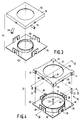
- Figure 4 shows an alternative embodiment of a holder 21 for an optical assembly in accordance with the invention, in which the elastically deformable element comprises four cylindrical elements 22, 23, 24 and 25 which define the vertices of an imaginary rectangle 60 surrounding apertures 61, 62 of holder plates 26, 27.
- the individual parts of the holder 21 are shown separately.
- the holder 21 is formed by assembling the first holder plate 26 and the second holder plate 27 together the rubber elements 22, 23, 24, 25 being inserted between them.
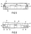
- the holder plates 26 and 27 are loosely coupled together and are provided with respective cooperating stop surfaces 28 and 29 which, in the assembled condition, are urged against one another by the rubber elements as the diagrammatic, sectional view of Figure 5 shows.
- the spacing between the first holder plate 26 and the second holder plate 27 is substantially constant throughout the entire surface of the holder plates.
- the two holder plates 26, 27 can be tilted relative to one another, for example, by pressing the holder plates towards one another at the location of the rubber element 22, as is shown in the schematic front view of Figure 6.
- the distance between the holder plates can be varied from, for example, d1 , at the location of the rubber element 22, to d2, at the location of the rubber element 23. If the pressure is removed at the location of the rubber element 22, the rubber elements will again urge the holder plates to a position in which their stop surfaces abut.
- the first holder plate 26 and the second holder plate 27 are provided with projections 30 and apertures 31 respectively which locate opposite ends of the rubber elements.
- the solid-state image sensor 70 is fixed to the second holder plate 27, for example, by means of an adhesive ( Figure 7).
- An image-receiving surface 72 of the solid-state image sensor 70 is accommodated in an envelope 73 of the image sensor 70 and it is assumed that its exact position relative to the envelope 73 is unknown.
- a test pattern is displayed on the entrance window of the colour-separation system, the test pattern being incident on the image-receiving surface 72 (see arrows in Figure 7) via the exit window 71 and passing through apertures 61, 62 of the holder 21.
- This test pattern is recorded by connecting the image sensor to a monitor (not shown in Figure 7).
- the image-receiving surface 72 can be oriented parallel to the exit window 71 by tilting the image sensor 70 until a desired test pattern is recorded.
- the two holder plates are rigidly secured to one another in this desired relative position.
- This can be carried out, for example, by means of an adhesive. Since an adhesive needs some time to cure the image sensor has to be held in the desired position during the curing time.
- a UV-curable adhesive is used so that the fixation can be carried out rapidly and in a defined manner.
- the image sensor is displaced over the exit window until a desired test pattern is displayed, after which the first holder plate 26 is secured to the exit window. If this displacement is not necessary the first holder plate 26 can be secured to the exit window at an earlier stage.
Landscapes
- Engineering & Computer Science (AREA)
- Multimedia (AREA)
- Signal Processing (AREA)
- Transforming Light Signals Into Electric Signals (AREA)
- Color Television Image Signal Generators (AREA)
Claims (5)
- Optische Einheit für eine Kamera mit einer Farbtrennanordnung (1), die ein Eintrittsfenster (2) und wenigstens ein Austrittsfenster (3, 4, 5, 71), und einen Festkörper-Bildsensor (6, 7, 8, 70) enthält, der am Austrittsfenster oder an jedem Austrittsfenster (3, 4, 5, 71) befestigt ist, wobei der Festkörper-Bildsensor eine in einem Kolben (73) angeordneten Bildempfangsfläche (72) enthält, die in bezug auf das entsprechende Austrittsfenster (3, 4, 5, 71) in einer vorgegebenen Stellung angeordnet ist, die wenigstens mittels eines Elements (52, 57, 58, 59, 22, 23, 24, 25) aus elastisch verformbarem Material bestimmt wird, dadurch gekennzeichnet, daß der oder jeder Festkörper-Bildsensor (6, 7, 8, 70) mit einer Halterung (9, 10, 11, 51, 21) am entsprechenden Austrittsfenster (3, 4, 5, 71) befestigt ist, die eine erste Halterungsplatte (12, 13, 14, 55, 26) mit geschlitzten Elementen an ihren Rändern enthält, die aus der ersten Halterungsplatte ausragen, wobei die Schlitze wenigstens durch eine erste Anschlagfläche (28) am Ende des Schlitzes begrenzt wird, der weitest von der Platte entfernt ist, und eine zweite Halterungplatte (15, 16, 17, 56, 27) mit zweiten Anschlagflächen (29) an ihren Rändern enthält, die in den Schlitzen der geschlitzten Elemente bewegbar ist, die Halterungsplatten zugewandte Öffnungen (45, 46, 47, 53, 61; 48, 49, 50, 54, 62) haben, die ersten und zweiten Halterungsplatten am entsprechenden Austrittsfenster (3, 4, 5, 71) bzw. am Festkörper-Bildsensor (6, 7, 8, 70) befestigt und aneinander befestigt sind, um die vorgegebene Position aufrechtzuerhalten, wobei die Halterung weiter das Element (52, 57, 58, 59, 22, 23, 24, 25) aus elastisch verformbarem Material in einer Position enthält, in der es mit den zwei Halterungsplatten zusammenarbeitet und zwischen diesen Platten wirksam ist.
- Optische Einheit nach Anspruch 1, dadurch gekennzeichnet, daß das elastisch verformbare Element, in Richtungen senkrecht auf die Halterungsplatten gesehen, die Öffnungen der Halterungsplatten umgibt.
- Optische Einheit nach Anspruch 1 oder 2, dadurch gekennzeichnet, daß das elastisch verformbare Element getrennte Segmente enthält, die, in Richtungen senkrecht auf die Halterungsplatten gesehen, wenigstens teilweise die Öffnungen in den Halterungsplatten umgibt.
- Optische Einheit nach Anspruch 1, 2 oder 3, dadurch gekennzeichnet, daß das elastisch verformbare Element vier getrennte Segmente enthält, die, in Richtungen senkrecht auf die Halterungsplatten gesehen, die Scheitelpunkte eines imaginären Rechtecks definieren, die die Öffnungen in den Halterungsplatten umgibt.
- Optische Einheit nach Anspruch 1, 2, 3 oder 4, dadurch gekennzeichnet, daß die ersten und zweiten Halterungsplatten mit Hilfe von ultraviolettaushärtendem Klebstoff aneinander befestigt werden.
Applications Claiming Priority (2)
| Application Number | Priority Date | Filing Date | Title |
|---|---|---|---|
| NL8801291 | 1988-05-19 | ||
| NL8801291A NL8801291A (nl) | 1988-05-19 | 1988-05-19 | Optisch samenstel voor een televisiecamera voorzien van een beeldsensor en werkwijze voor het vervaardigen van zulk een optisch samenstel. |
Publications (2)
| Publication Number | Publication Date |
|---|---|
| EP0342753A1 EP0342753A1 (de) | 1989-11-23 |
| EP0342753B1 true EP0342753B1 (de) | 1994-08-03 |
Family
ID=19852320
Family Applications (1)
| Application Number | Title | Priority Date | Filing Date |
|---|---|---|---|
| EP89201220A Expired - Lifetime EP0342753B1 (de) | 1988-05-19 | 1989-05-16 | Optisches Gefüge für eine Fernsehkamera mit einem Bildsensor |
Country Status (6)
| Country | Link |
|---|---|
| US (1) | US4933752A (de) |
| EP (1) | EP0342753B1 (de) |
| JP (1) | JP2765723B2 (de) |
| KR (1) | KR900018731A (de) |
| DE (1) | DE68917204T2 (de) |
| NL (1) | NL8801291A (de) |
Families Citing this family (7)
| Publication number | Priority date | Publication date | Assignee | Title |
|---|---|---|---|---|
| US4890899A (en) * | 1987-05-18 | 1990-01-02 | Matsushita Electric Industrial Co., Ltd. | Color separation optical system which utilizes glass frit for bonding |
| US5134468A (en) * | 1989-02-21 | 1992-07-28 | Canon Kabushiki Kaisha | Optical apparatus for varying the lengths of optical path of color component light beams |
| US5510937A (en) * | 1992-12-14 | 1996-04-23 | Asahi Kogaku Kogyo Kabushiki Kaisha | Apparatus for adjusting intermeshing angle in feed screw mechanism |
| RU2120196C1 (ru) * | 1997-09-29 | 1998-10-10 | Московское конструкторское бюро "Электрон" | Блок светоделительной призмы и прибора с зарядовой связью и способ сборки под юстировку этого блока |
| US6956610B1 (en) * | 1999-02-18 | 2005-10-18 | Linvatec Corporation | Shock mounting system for CCD camera |
| US7557860B2 (en) * | 2004-11-04 | 2009-07-07 | Linvatec Corporation | Elastomeric camera mounting system |
| JP2007166299A (ja) * | 2005-12-14 | 2007-06-28 | Sony Corp | 固体撮像素子、色分解撮像光学系及び撮像装置 |
Family Cites Families (9)
| Publication number | Priority date | Publication date | Assignee | Title |
|---|---|---|---|---|
| GB2078935A (en) * | 1980-05-16 | 1982-01-13 | Bell & Howell Co | Colour-separating optical system with positioned photodetector |
| JPS5842004A (ja) * | 1981-09-07 | 1983-03-11 | Canon Inc | 光学素子の位置決め方法 |
| US4591901A (en) * | 1984-03-30 | 1986-05-27 | Rca Corporation | Television camera with solid-state imagers mounted to a prism |
| JPS6116690A (ja) * | 1984-07-03 | 1986-01-24 | Olympus Optical Co Ltd | 撮像装置 |
| US4622580A (en) * | 1984-09-26 | 1986-11-11 | Rca Corporation | Solid-state imager chip mounting |
| JP2606185B2 (ja) * | 1985-06-17 | 1997-04-30 | ソニー株式会社 | 固体撮像素子のレジストレーション測定方法 |
| US4789891A (en) * | 1985-09-11 | 1988-12-06 | Fuji Photo Optical Co., Ltd. | Spacer with an inclined surface for mounting a solid image pickup element to a color separation prism |
| US4835600A (en) * | 1986-07-21 | 1989-05-30 | Konishiroku Photo Industry Co., Ltd. | Solid state image reading device with sensors adhered to plate which is adhered to lens holding member |
| JPS63267087A (ja) * | 1987-04-24 | 1988-11-04 | Matsushita Electric Ind Co Ltd | カラ−固体撮像装置 |
-
1988
- 1988-05-19 NL NL8801291A patent/NL8801291A/nl not_active Application Discontinuation
-
1989
- 1989-05-16 JP JP1120614A patent/JP2765723B2/ja not_active Expired - Fee Related
- 1989-05-16 EP EP89201220A patent/EP0342753B1/de not_active Expired - Lifetime
- 1989-05-16 DE DE68917204T patent/DE68917204T2/de not_active Expired - Fee Related
- 1989-05-16 US US07/352,422 patent/US4933752A/en not_active Expired - Lifetime
- 1989-05-16 KR KR1019890006503A patent/KR900018731A/ko not_active Withdrawn
Also Published As
| Publication number | Publication date |
|---|---|
| DE68917204T2 (de) | 1995-03-02 |
| JP2765723B2 (ja) | 1998-06-18 |
| US4933752A (en) | 1990-06-12 |
| EP0342753A1 (de) | 1989-11-23 |
| JPH0222969A (ja) | 1990-01-25 |
| NL8801291A (nl) | 1989-12-18 |
| KR900018731A (ko) | 1990-12-22 |
| DE68917204D1 (de) | 1994-09-08 |
Similar Documents
| Publication | Publication Date | Title |
|---|---|---|
| US4644632A (en) | Method of assembling the optical components of an optical apparatus and a device therefor | |
| US4594613A (en) | Solid-state imaging device assembly | |
| EP0342753B1 (de) | Optisches Gefüge für eine Fernsehkamera mit einem Bildsensor | |
| JPH0843667A (ja) | 光ファイバを基質に形成された導波管に連結する装置 | |
| US4531818A (en) | Adapter for arranging an instant picture cassette at a 35 mm camera and method for manufacturing the same | |
| JPH05323230A (ja) | 画像装置 | |
| CA1281535C (en) | Method and apparatus for producing folded optical path devices | |
| JPH05100136A (ja) | 撮像装置 | |
| JPS5842004A (ja) | 光学素子の位置決め方法 | |
| JPH11160442A (ja) | X線画像検出器およびその製造方法 | |
| US5659815A (en) | Focus detection device | |
| JPH0557958A (ja) | 画像ヘツド | |
| TWI881387B (zh) | 電子部件處理設備用檢查裝置 | |
| JPH01126869A (ja) | 固体撮像素子の取付方法 | |
| JPS5863279A (ja) | カラ−撮像装置 | |
| JPH0884217A (ja) | 画像読取装置における固体撮像素子の取付構造 | |
| JPH03259691A (ja) | 固体撮像装置 | |
| JPH0862480A (ja) | 測距装置のレンズ組立構造およびレンズ位置調整方法 | |
| US6064831A (en) | Attaching method for a magnetic head used in a camera and attachment for the same | |
| JPH05308645A (ja) | 光学装置 | |
| US5541689A (en) | Plate frame for use in large-format camera enabling mounting of a smaller size film holder | |
| JPH10133264A (ja) | カメラバック交換式カメラ | |
| JPH0937275A (ja) | 固体撮像装置及び固体撮像素子部取付方法 | |
| GB2078935A (en) | Colour-separating optical system with positioned photodetector | |
| JPH04334160A (ja) | 密着型イメージセンサユニット |
Legal Events
| Date | Code | Title | Description |
|---|---|---|---|
| PUAI | Public reference made under article 153(3) epc to a published international application that has entered the european phase |
Free format text: ORIGINAL CODE: 0009012 |
|
| AK | Designated contracting states |
Kind code of ref document: A1 Designated state(s): DE FR GB NL |
|
| 17P | Request for examination filed |
Effective date: 19900518 |
|
| 17Q | First examination report despatched |
Effective date: 19920413 |
|
| GRAA | (expected) grant |
Free format text: ORIGINAL CODE: 0009210 |
|
| AK | Designated contracting states |
Kind code of ref document: B1 Designated state(s): DE FR GB NL |
|
| PG25 | Lapsed in a contracting state [announced via postgrant information from national office to epo] |
Ref country code: NL Effective date: 19940803 |
|
| REF | Corresponds to: |
Ref document number: 68917204 Country of ref document: DE Date of ref document: 19940908 |
|
| ET | Fr: translation filed | ||
| NLV1 | Nl: lapsed or annulled due to failure to fulfill the requirements of art. 29p and 29m of the patents act | ||
| PLBE | No opposition filed within time limit |
Free format text: ORIGINAL CODE: 0009261 |
|
| STAA | Information on the status of an ep patent application or granted ep patent |
Free format text: STATUS: NO OPPOSITION FILED WITHIN TIME LIMIT |
|
| REG | Reference to a national code |
Ref country code: FR Ref legal event code: CD |
|
| 26N | No opposition filed | ||
| REG | Reference to a national code |
Ref country code: FR Ref legal event code: CD |
|
| REG | Reference to a national code |
Ref country code: GB Ref legal event code: IF02 |
|
| PGFP | Annual fee paid to national office [announced via postgrant information from national office to epo] |
Ref country code: FR Payment date: 20020527 Year of fee payment: 14 |
|
| PGFP | Annual fee paid to national office [announced via postgrant information from national office to epo] |
Ref country code: GB Payment date: 20020531 Year of fee payment: 14 |
|
| PGFP | Annual fee paid to national office [announced via postgrant information from national office to epo] |
Ref country code: DE Payment date: 20020719 Year of fee payment: 14 |
|
| PG25 | Lapsed in a contracting state [announced via postgrant information from national office to epo] |
Ref country code: GB Free format text: LAPSE BECAUSE OF NON-PAYMENT OF DUE FEES Effective date: 20030516 |
|
| PG25 | Lapsed in a contracting state [announced via postgrant information from national office to epo] |
Ref country code: DE Free format text: LAPSE BECAUSE OF NON-PAYMENT OF DUE FEES Effective date: 20031202 |
|
| GBPC | Gb: european patent ceased through non-payment of renewal fee |
Effective date: 20030516 |
|
| PG25 | Lapsed in a contracting state [announced via postgrant information from national office to epo] |
Ref country code: FR Free format text: LAPSE BECAUSE OF NON-PAYMENT OF DUE FEES Effective date: 20040130 |
|
| REG | Reference to a national code |
Ref country code: FR Ref legal event code: ST |