EP0342697A2 - Druckvorrichtung mit manueller Abtastung - Google Patents
Druckvorrichtung mit manueller Abtastung Download PDFInfo
- Publication number
- EP0342697A2 EP0342697A2 EP89109062A EP89109062A EP0342697A2 EP 0342697 A2 EP0342697 A2 EP 0342697A2 EP 89109062 A EP89109062 A EP 89109062A EP 89109062 A EP89109062 A EP 89109062A EP 0342697 A2 EP0342697 A2 EP 0342697A2
- Authority
- EP
- European Patent Office
- Prior art keywords
- printing
- rotor
- take
- printing device
- scanning type
- Prior art date
- Legal status (The legal status is an assumption and is not a legal conclusion. Google has not performed a legal analysis and makes no representation as to the accuracy of the status listed.)
- Withdrawn
Links
- 238000007639 printing Methods 0.000 title claims abstract description 253
- 230000007246 mechanism Effects 0.000 claims description 8
- 238000005192 partition Methods 0.000 claims description 7
- 230000015572 biosynthetic process Effects 0.000 claims description 4
- 230000035515 penetration Effects 0.000 claims 2
- 230000008878 coupling Effects 0.000 claims 1
- 238000010168 coupling process Methods 0.000 claims 1
- 238000005859 coupling reaction Methods 0.000 claims 1
- 238000001514 detection method Methods 0.000 description 22
- 229910052751 metal Inorganic materials 0.000 description 15
- 239000002184 metal Substances 0.000 description 15
- 230000006870 function Effects 0.000 description 12
- 238000010276 construction Methods 0.000 description 9
- 230000004044 response Effects 0.000 description 9
- 238000012546 transfer Methods 0.000 description 5
- 230000020169 heat generation Effects 0.000 description 4
- 230000005540 biological transmission Effects 0.000 description 3
- 230000000994 depressogenic effect Effects 0.000 description 3
- 238000010586 diagram Methods 0.000 description 3
- 230000002093 peripheral effect Effects 0.000 description 3
- 238000000926 separation method Methods 0.000 description 3
- 238000003780 insertion Methods 0.000 description 2
- 230000037431 insertion Effects 0.000 description 2
- WABPQHHGFIMREM-UHFFFAOYSA-N lead(0) Chemical compound [Pb] WABPQHHGFIMREM-UHFFFAOYSA-N 0.000 description 2
- 238000012986 modification Methods 0.000 description 2
- 230000004048 modification Effects 0.000 description 2
- 238000012545 processing Methods 0.000 description 2
- OJIJEKBXJYRIBZ-UHFFFAOYSA-N cadmium nickel Chemical compound [Ni].[Cd] OJIJEKBXJYRIBZ-UHFFFAOYSA-N 0.000 description 1
- 238000012937 correction Methods 0.000 description 1
- 238000012217 deletion Methods 0.000 description 1
- 230000037430 deletion Effects 0.000 description 1
- 230000000881 depressing effect Effects 0.000 description 1
- 230000005764 inhibitory process Effects 0.000 description 1
- 229920003023 plastic Polymers 0.000 description 1
- 230000005855 radiation Effects 0.000 description 1
- 238000010023 transfer printing Methods 0.000 description 1
- 239000012780 transparent material Substances 0.000 description 1
- 125000000391 vinyl group Chemical group [H]C([*])=C([H])[H] 0.000 description 1
- 229920002554 vinyl polymer Polymers 0.000 description 1
Images


Classifications
-
- B—PERFORMING OPERATIONS; TRANSPORTING
- B41—PRINTING; LINING MACHINES; TYPEWRITERS; STAMPS
- B41J—TYPEWRITERS; SELECTIVE PRINTING MECHANISMS, i.e. MECHANISMS PRINTING OTHERWISE THAN FROM A FORME; CORRECTION OF TYPOGRAPHICAL ERRORS
- B41J3/00—Typewriters or selective printing or marking mechanisms characterised by the purpose for which they are constructed
- B41J3/28—Typewriters or selective printing or marking mechanisms characterised by the purpose for which they are constructed for printing downwardly on flat surfaces, e.g. of books, drawings, boxes, envelopes, e.g. flat-bed ink-jet printers
Definitions
- This invention relates to a manual scanning type printing device.
- Such a printing device is disclosed in, for example, U.S.P. specification No. 3,767,020.
- this manual scanning type printing device when a long and narrow casing member is laid and scanned on the paper, rollers of the casing member are rotated on the paper. The rotation movement of the rollers are transmitted to an ink tape take-up shaft and encode plate via transmission gears, the ink tape is taken up, and the rotation angle of the encode plate is detected by means of a rotation sensor. Then, the printing head is driven according to the detected signal of the rotation sensor to print the preset information on the paper via the ink tape (refer to Fig. 4 in the U.S.P. specification). The ink tape is moved in a direction perpendicular to that of the movement of the casing member and is taken up by the tape take-up shaft.
- the encode plate is rotated in the same direction as the paper-contact roller and the ink tape is taken up in a direction perpendicular to the' scanning direction of the casing member. Therefore, the transmission gear connected to the paper-contact roller must be constituted to have two trains of gears for respectively driving the encoder plate and the ink tape. More specifically, a train of the encoder driving gears is constituted to have an intermediate gear which can be formed of a spur gear and arranged on a line since the axes of the encode plate and the paper-contact roller are parallel with each other.
- the intermediate gear must be formed of a bevel gear so as to convert the rotation direction of the paper-contact roller to that of the ink tape take-up shaft.
- the width of the printing device becomes extremely large. Therefore, when scanning the casing member, it becomes necessary to set the casing member in parallel with and close to the paper. With this construction, when it is required to print information on small recording paper such as a pocket notebook or specified area, the paper-contact roller may run off the paper, preventing the adequate printing operation.
- An object of this invention is to provide a manual scanning type printing device which can be formed simple in construction and with a narrow width and in which rotation of the paper-contact roller can be serially transmitted to the ink tape take-up shaft and the encode plate, thus permitting information to be printed on small recording paper such as a pocket notebook or specified area.
- a manual scanning type printing device comprising a casing member formed in cylindrical configuration having a longitudinal hollow portion; a driving rotor disposed on the bottom side of the casing member so as to be rotated on recording paper; a printing head arranged on the bottom side of the hollow portion of the casing member and having a printing element formation surface in which a plurality of printing elements are arranged; resilient supporting means arranged in the hollow portion of the casing member, for biasing the printing head to press the printing element formation surface against the recording paper; an ink tape take-up rotor arranged in the hollow portion of the casing member, for taking up an ink tape of an ink tape cassette mounted in the hollow portion of the casing member; at least one first intermediate rotor disposed between the driving rotor and the ink tape take-up rotor; a second intermediate rotor disposed between the first intermediate rotor and the driving rotor or above the ink tape take-up rotor; and an encode plate coupled to the second intermediate
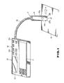
- Fig. 1 is an exterior view of one embodiment of this invention applied to a word processor.
- Word processor body 10 is a stationary type, for exam- pie.
- Key input section 11, function keys 12 and display unit 13 are provided on word processor 10.
- Key input section 11 includes a number of input keys for inputting numerals, characters and the like.
- function keys 12 include interruption key 12a and normal/reverse key 12c in addition to a mode selection key for selecting a word processor mode or printing mode,. an execution key for specifying the start and end of document input, and various keys used in a general word processpr for specifying the insertion, deletion and correction of an input sentence or sentences.
- Interruption key 12a is a key for specifying separation between desired clauses of an input document.
- Normal/reverse key 12c is used to specify the operation of printing reversed characters when printing a character series of the separated document on a transparent material, for example. Characters and symbols input by key input section 11 and function keys 12 are sequentially displayed on display unit 13.
- Thermal head unit 17 is disposed on the bottom portion of printing device 1.
- Thermal head unit 17 has thermal head 24 shown in Fig. 2.
- thermal head 24 is a line type thermal head with a line of 48 dots and the direction in which the line of dots extends is set in parallel with the width direction of printing device 1.
- An operator may input desired document data by operating the mode selection key to specify the word processor mode and then operating various keys of key input section 11.
- interruption key 12a is operated for each clause of the input document.
- interruption key 12a is operated, a preset separation code (interruption code) is input and symbol is displayed on display unit 13.
- the operator specifies the printing mode by operating the mode selection key. Then, the operator sets thermal head unit 17 of printing device 1 in contact with the surface ;of recording paper A and moves printing device 1 in a direction indicated by arrow X with printing switch 14s kept depressed. As a result, the input document is printed on recording paper A.
- Printing observing window 14x is formed on the lower rear side portion of printing device 1 by partly cutting away the lower rear side portion of printing device 1. The printing position with respect to recording paper A can be correctly determined by observing thermal head 24 via observing window 14x.
- the document data displayed on display unit 13 is scrolled by operation of the cursor key.
- the operator may operate the cursor key while observing the displayed document data so as to select a desired character series separated as printing character data by the interruption code.
- the operator can specify the printing operation of normal (real image) printing or reversed (mirror image) character printing by setting the cursor on the position of the interruption code attached behind the selected character series and operating normal/reverse key 12c.
- specified printing recognition mark representing the specified direction and the printing operation of normal printing or reversed character printing is displayed instead of mark 1m in position of the interruption code of the document character series selected as printing character data on display unit 13.
- Fig. 2 shows the structure of printing section 20 formed in printing device 1.
- casing body 14 of printing device 1 is formed in a hollow cylindrical configuration.
- Ink tape cassette 21 is detachably mounted on printing section 20.
- Ink tape cassette 21 includes take-up spool 22a for taking up ink tape 23 and supply spool 22b for feeding out ink tape 23.
- Thermal transfer ink tape 23 partly extends out from the lower portion of ink tape cassette 21 and both ends of the tape are fixed on spools 22a and 22b.
- Thermal head unit 17 is disposed on the lower portion of printing section 20.
- Thermal head unit 17 includes thermal head 24. The heat radiation surface of thermal head 24 slightly protrudes from the bottom surface of casing body 14.
- Thermal head 24 has a line type heat generator disposed on the lower flat portion thereof. Further, thermal head 24 is mounted so as to be vertically moved with respect to head mounting member 25. Thermal head 24 normally biased downwardly by means of coil spring 16 disposed between thermal head 24 and head mounting member 25 so that a desired printing pressure can be obtained. Further, ink ribbon guide section 26 and sliding contact sections 27a and 27b which slide on recording paper A in the printing operation are formed integrally with head mounting member 25. Sliding contact sections 27a and 27b are separately arranged in the width direction of thermal head 24 and the intermediate portion therebetween is cut away. The cut-away portion is used as printing recognition window 14X.
- Connector 28 formed of a flexible base plate is connected to thermal head 24.
- a printing control signal for thermal head 24 is supplied to thermal head 24 via connector 28.
- Frame 30 is mounted on the bottom surface portion of casing body 14 in which thermal head 24 is arranged.
- Rubber roller 29 is mounted in front of frame 30. When printing device 1 is moved in the direction indicated by arrow X in the printing operation, rubber roller 29 rotates in contact with recording paper A.
- Driving gear 31 having a shaft which is also used as a supporting shaft of rubber roller 29 is fixed on the side portion of rubber roller 29.
- Driving gear 31 is formed with a diameter smaller than that of rubber roller 29.
- Driving gear 31 is coupled to encode plate 36 via intermediate gears 32, 33, 34a, 34b and 35.
- Encode plate 36 is fixed on one surface of intermediate gear 35 so as to be rotated together with intermediate gear 35. Traveling distance detecting sensor 38 including LED 37a and photosensor 37b is disposed near encode plate 36. A plurality of slits 36a, 36b,... are radially formed in peripheral portion of encode plate 36 at regular intervals. LED 37a and photosensor 37b are arranged with encode plate 36 disposed therebetween. Light emitted from LED 37a is transmitted to photosensor 37b via slits 36a, 36b,... of encode plate 36. Encode plate 36 is rotated by moving printing device 1 in direction X, and light transmitted from LED 37a to photosensor 37b is interrupted at a rate corresponding to the moving speed of the printing device. That is, encode plate 36, LED 37a and photosensor 37b are combined to constitute encoder 39 for detecting the moving speed of printing device 1.
- Intermediate gear 35 integrally connected with encode plate 36 is further coupled with take-up gear 41 via intermediate gear 40. Therefore, rotation of rubber roller 29 is transmitted to encode plate 36 and to take-up gear 41.
- Take-up shaft 42 for ink tape 23 is mounted on the central portion of take-up gear 41.
- Stopper arm 43 is disposed on the stem portion of take-up shaft 42. Stopper arm 43 is pivotally mounted on take-up shaft 42. Stopper gear 44 which is engaged with take-up gear 41 is mounted on the tip end of stopper arm 43.
- Ink tape cassette 21 is mounted on printing section 20 with take-up shaft 42 used as its supporting shaft.
- Thermal transfer ink tape 23 extending outwardly from cassette 21 at the lower portion thereof is guided by means of ink tape guide section 26 and set in contact with the head surface of thermal head 24.
- Ink tape guide section 26 serves to guide ink tape 23 so as to precisejy set it on the head surface of thermal head 24.
- Ink tape guide section 26 is integrally formed with head mounting section 25 near thermal head 24. Therefore, it is not necessary to provide the guide members in ink tape cassette 21.
- ink tape cassette 21 can be made smaller, reducing the whole size of printing device 1.
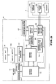
- Fig. 3 shows the construction of electronic circuits formed in word processor body 10 and printing device 1.
- 51 denotes a control section.
- Control section 51 is supplied with various key input operation signals from key input section 11 and function keys 12, a printing signal from print switch 14s disposed in printing device 1 and a pulse signal corresponding to the traveling distance of printing device 1 or a traveling distance detection signal.
- Control section 51 controls memory section 52, display character generator 53, printing character generator 54 and printing control section 55 in response to various key operation signals or switching operation signals from key input section 11, function keys 12 and printing switch 14s.
- control section 51 supplies a normal/reverse signal to character pattern converting section 57 in response to the input operation of normal/reverse key 12c.
- Memory section 52 stores document information formed by the key input operation in the form of character code. Upon the document input operation, an interruption code input for each desired clause by operation of interruption key 12a is stored in memory section 52 together with the character codes of document data.
- Display unit 13 displays characters or symbols corresponding to the received data.
- the character data and symbol data are also supplied to printing character generator 54 which in turn generates a pattern of characters or symbols to be actually printed and corresponding to the received data.
- the pattern generated from printing character generator 54 is supplied to character pattern converting section 57.
- Converting section 57 converts the pattern output order of the printing pattern in response to the normal/reverse signal from control section 51, and supplies the converted pattern output order to printing buffer 58 which in turn stores the received data.
- a printing signal generated by turning on printing switch 14s of printing device 1 is supplied to control section 55.
- control section 55 While the printing signal is being generated, when printing control section 55 receives an encoder pulse from encoder 39, control section 55 transfers the character pattern stored in printing buffer 58 for each line to thermal head 24 of printing device 1 in response to the encoder pulse. Assume now that the printing quality of thermal head 24 is 24 x 24 dots (em). The one line indicates 1 line of 24 lines which constitute one character.
- the character pattern supplied from printing character generator 54 is sequentially output one by one by 24 lines from the leftmost column in the right direction in the normal printing operation.
- the pattern is sequentially output one by one by 24 lines from the rightmost column in the left direction.
- Interrupt code determination section 59 serves to detect the "interrupt” code in the character code read out from memory section 52 in the printing mode. That is, interrupt code determination section 59 detects the readout of the "interrupt” code. When detecting the "interrupt” code, interrupt code determination section 59 generates an interrupt code detection signal which is in turn supplied to control section 51 and printing control section 55.
- control section 51 has a function of determining the contents of a normal/reverse flag (normal printing specification "0"; reversed character printing specification "1") which is stored together with the interrupt code read out from memory section 55.
- Control section 51 supplies a normal/reverse control signal to character pattern converting section 57 according to the contents of the normal/reverse flag.
- a corresponding "interrupt" code mark on display unit 13 is converted into a or mark corresponding to the contents of the specified printing and displayed thereon.
- the character data read out from memory section 52 in the printing operation is converted into a pattern corresponding to the specified printing mode (normal printing mode or reverse printing mode) by means of character pattern converting section 57.
- the pattern is supplied from printing buffer 58 to thermal head 24 via printing control section 55 and is printed.
- the interrupt code is detected in the printing operation in which an encoder pulse is output, the operation of control section 51 for specifying an readout address of memory section 52 is interrupted, and the operation of printing control section 55 for controlling the printing operation of thermal head 24 is interrupted.
- Fig. 4 shows the construction of an interrupt code stored in memory section 52.
- the interrupt code stored in memory section 52 is formed with 2-byte configuration.
- An interrupt character code corresponding to the interrupt code is stored in the preceding one-byte of the 2-byte configuration and the normal/reverse flag, character modification code and the like are stored in the remaining one-byte area.
- the character modification and the normal- or reversed-character printing specifications in document data are checked based on the contents of the top interrupt code.
- the operator selects a desired character series in the document data, specifies the top interrupt code and operates normal/reverse key 12c, then the normal/reverse flag is set at the memory area as shown in Fig. 4.
- the input document data is sequentially set into memory areas of memory section 52 whose addresses are specified by control section 51. In this case, the operator depresses interrupt key 12c at each end of desired clauses.
- the input document data is supplied via display character generator 53 and display buffer 56 and is displayed on display unit 13.
- Fig. 5 shows the state in which input document data is stored in memory section 52.
- the document data stored in memory section 52 includes a separation code ("interrupt code) set in position corresponding to the input position of interrupt key 12c operated at each end of desired clauses.
- the "interrupt" code is used as data for determining the normal printing/reverse printing mode when the document data is printed.
- control section 51 is set into the printing mode.
- memory section 52 is set into a state in which the stored data can be read out, and printing control section 55 is set into a wait condition for the input of an encoder pulse from encoder 39. In this condition, the operator moves printing device 1 in a direction indicated by arrow X, while keeping thermal head 24 in contact with recording paper A and printing switch 14s depressed as shown in Fig. 1.
- the operator can visually determine the printing position by thermal head 24 and ink tape 23 by observing the internal portion via printing determination window 14x which lies on the rear side of printing device 1 with respect to moving direction X. Therefore, the operator can precisely set the printing area in position corresponding to a ruled line or the like on recording paper A, for example.
- a pulse signal generated from photosensor 37b in response to the forward rotation of encode plate 36 is used as an output signal of encoder 39, and is supplied as a detection signal corresponding to the traveling distance to control section 51 and printing control section 55.
- Rotation of intermediate gear 35 is also transmitted to tape take-up gear 41 and tape take-up shaft 42 via intermediate gear 40, and to take-up spool 22b in ink tape cassette 21.
- take-up spool 22b rotates to take up thermal ink tape 23 which has been fed out from supply spool 22a and passed the head surface of thermal head 24 and ink tape guide 26.
- tape take-up shaft 42 rotates with the movement of printing device 1 so as to prevent occurrence of slip between recording paper A and ink tape 23.
- Thermal head 24 is biased by means of coil spring 16 disposed between thermal head 24 and member 25. Ink tape 23 is pressed against recording paper A with a preset force by thermal head 24 which is biased by a spring force of coil spring 16. In this case, the stable contact state between thermal head 24 and recording paper A can be held by an adequate contact condition between recording paper and each of rubber roller 29 disposed on one side of thermal head 24 and sliding contact sections 27a and 27b disposed separately from thermal head 24.
- tape take-up gear 41 rotates in a forward direction, and stopper arm 43 is held in position separated from gear 44.
- a traveling distance detection signal output from photosensor 37b in the form of an encoder pulse is supplied as an output signal of encoder 39 to control section 51 and printing control section 55.
- Control section 51 sequentially designates memory addresses of memory section 52 in response to the traveling distance detection signal from encoder 39, and reads out document data stored in the designated memory area.
- the readout document data is supplied to printing character generator 54.
- Character generator 54 generates pattern data for individual characters.
- the pattern data generated is supplied to printing buffer 58 via character pattern converting section 57.
- Printing control section 55 drives thermal head 24 in synchronism with the traveling distance detection signal from encoder 39 (that is, in synchronism with , the readout timing of document data by means of control section 51).
- document data is thermally transferred to recording paper A via ink tape 23.
- new or unused portion of ink tape 23 is supplied from supply spool 22a of ink tape cassette 21.
- the used portion of ink tape 23 which has been used for thermal transfer printing by thermal head 24 passes tape guide section 26 and is taken up by means of take-up spool 22b in ink tape cassette 21.
- the document data stored in memory section 52 is sequentially printed on recording paper A for each character series of clauses divided by the "interrupt" code by moving printing device 1 in the X direction.
- Control section 51 designates the top address in memory section 52 and the contents of the interrupt code stored in the address position is checked by means of interrupt code determination section 59.
- determination section 59 determines that the character series "CASIO" of the divided clause following the
- SD mark should be printed in a normal fashion, and displays the normal El mark on display unit 13 as shown in Fig. 7A.
- one character code (“C” in this case) of the character series in the same clause is supplied to printing character generator 54 (steps S2 and S3).
- printing character generator 54 supplies character pattern "C” to character pattern converting section 57 (step S4).
- control section 51 does not generate a control signal which specifies the reversed-character printing operation
- character pattern converting section 57 supplies the received character pattern "C” to printing buffer without converting the pattern thereof and thus the character pattern "C” is stored in printing buffer 58 as it is (step S5).
- step S6 to S8 When the operator operates printing switch 14s of printing device 1 and moves printing device 1 on recording paper A in the X direction (in response to an encoder pulse from encoder 39), data is printed for each line in the right direction starting from the leftmost column of character pattern "C" as shown by area m in Fig. 8 (steps S6 to S8). Thus, the operation of printing the head character for each line is completed. Then, the readout address for memory section 52 is incremented.
- the character patterns of the succeeding printing character codes (“A"-"S"-"1"-, in this example) are sequentially read “ out from printing character generator 54 and normally printed in a lateral direction on recording paper A (steps S8 to S10) until the "interrupt" code set at the top of the next clause is read out.
- step S1 and S2 the readout address of memory section 52 (for the character series "CASIO") is incremented until an interrupt code attached to the head of the next clause is read out (steps S11 and S12).
- step S11 and S12 the readout address of memory section 52 is decremented, and the last character code ("0" in this example) of the character series designated by he readout address is supplied to printing character generator 54 (steps S13 to S15). Character pattern "0" generated from printing character generator 54 is supplied to character pattern converting section 57 (step S16).
- Control section 51 outputs a control signal for specifying the reverse-printing operation.
- Character pattern "0" supplied to character pattern converting section 57 is stored in printing buffer 58 with the column order reversed so as to be read out for each column from the rightmost column towards the leftmost column (step S17).
- control section 55 starts the operation of printing character pattern "0" for each line from the rightmost column towards the leftmost column in response to an encoder pulse from encoder 39 (steps S18 to S20).
- the readout address of memory section 52 is further decremented.
- the normal printing and reverse printing can be selectively specified for each character series previously divided by the interrupt code. Further, printing style information can be checked by the interrupt code and determined at the readout operation for printing, and the pattern of the printing character is converted into the specified style according to the determined printing style information and printed.
- the reverse (mirror image) printing operation is effected to print characters in the reversed form on the rear side of a casing such as a transparent plastic case or vinyl bag so that the printed characters can be correctly observed from the front side. In this case, the printed characters can be prevented from being rubbed with other things and will not be smeared or erased.
- an input section for receiving an image to be printed is provided in word processor body 10 separated from printing device 1, and printing device 1 and word processor body 10 are connected by means of connection code 15.
- connection code 15 it is also possible to provide the input section for the image to be printed in the printing device, thereby making the device portable.
- the portable type printing device is explained below.
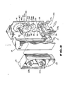
- Figs. 9 and 10 show the construction of manual scanning type printing device 100.
- Printing device 100 is used to read image data on paper and print the readout image data on different paper, for example.
- Readout section 102 is mounted in the upper portion of longitudinal casing member 101 of printing device 100, printing section is mounted in the lower portion thereof, and battery 104 is mounted in the intermediate portion thereof.
- casing member 101 is formed with a longitudinal hollow cylinder, and the upper portion thereof is slightly tapered. Further, as shown in Fig. 10, casing member 101 is formed to include right side casing 105, upper right small casing 106, opening/closing lid 107 disposed below casing 106 and upper lid 108 on the top end. The bottom portion thereof is made open. Portion of right side casing 105 ranging from the tapered top end to the bottom end is formed with a "]"-shaped cross section. Bosses 109 having a threaded hole formed therein is formed in the inner wall of casing 105. Circuit board 110 is fixed by setting screws into bosses 109 and internal casing 111 is fixed to cover circuit board 110.
- upper right side small casing 106 is fixed on the upper side of casing 105 to constitute a reading member receiving section.
- Bearing portions 113 are oppositely arranged on both ends of the upper portion of reading member receiving section 112, that is, the front upper corner portion in small casing 106 and the front upper corner portion in casing 105 in Fig. 10.
- Reading guide recess portion 114 is formed to extend in a longitudinal direction along the inclined side surface of the rear left wall of small casing 106 in Fig. 10. Opening/closing lid 107 is detachably mounted on casing 105 at the lower portion thereof.
- Opening/closing lid 107 is formed with a "]"- shaped cross section, and engaging hooks 117 are formed on both edges thereof. Opening/closing lid 107 is detachably mounted on casing 105 by engaging hooks 117 with engaging portions 118.
- circuit board 110 is mounted on circuit board 110 attached to casing 105.
- Circuit board 110 is formed to extend along the inner wall of casing 105 between printing member receiving section 115 and battery receiving section 116.
- Internal casing 111 in which circuit board 110 is attached is formed in a thin longitudinal box form, and partition section 120 horizontally bent and extending in the left direction in the drawing is formed in the upper portion of casing 111.
- Partition section 120 is used to receive battery 104.
- Portion of internal casing 111 ranging from the intermediate portion to the lower portion thereof is made thin, and metal plate 121 of printing section 103 to be described later is attached to the thin portion.
- Partition section 120 in the upper portion of internal casing 111 also has a function of separating reading member receiving section 112 and battery receiving section 116 from one another.
- Two recesses 122 are formed in the internal surface of partition section 120, and battery terminal boards 123 are mounted in recesses 122. Battery terminal boards 123 are disposed in contact with electrodes 104a of battery 104. Further, battery terminal boards 123 are connected to circuit board 110 via lead wires (not shown).
- reading section 102 received in reading member receiving section 112 is explained.
- Reading section 102 is used to read out image data on paper, and includes rubber roller 124, encoder unit 125 reader unit 126 and upper lid 108.
- Rubber roller 124 is rolled on the paper when image data on the paper is read.
- the lower half portions of end shaft portions 124a of rubber roller 124 are received in bearing portions 113 formed in casing 105 and small casing 106, and the upper half portions of the end shaft portions are held by upper lid 108.
- the upper portion of rubber roller 124 is disposed to partially protrude from the upper end surface of casing 101.
- Encoder unit 125 serves to detect the traveling distance of printing device 1 with respect to paper.
- Encoder unit 125 is constituted by mounting rubber roller 128, intermediate gear 129, encode plate 130 and traveling distance detecting sensor 131 on mounting plate 127.
- Mounting plate 127 is mounted on the right side wall of casing 105 in reading member receiving section 112.
- Rubber roller 128 is rolled on paper in the same manner as rubber roller 124.
- Rubber roller 124 is rotatably mounted on shaft 132 fixed on mounting plate 127 together with driving gear 133.
- the upper portion of rubber roller 128 is disposed to protrude upwardly of mounting plate 127.
- Intermediate gear 133 is rotatably mounted on mounting plate 127 and rotated in engagement with driving gear 133 to transmit rotation of rubber roller 128 to encode plate 130.
- Encode plate 130 is rotated together with rubber roller 128, and is formed of a disc having a number of slits 130a formed on the peripheral portion thereof.
- Encode plate 130 is rotatably mounted on shaft 134 fixed on mounting plate 127 together with driven gear 135. Driven gear 135 is engaged with intermediate gear 129.
- Traveling distance detecting sensor 131 detects the rotation speed of encode plate 130, and is constructed by an LED and a photosensor disposed on both sides of encode plate 130. The functions of the LED and photosensor are the same as those of LED 37a and photosensor 37b in the first embodiment. Traveling distance detecting sensor 131 is connected to circuit board 110 via lead wire 131 b.
- Reader unit 126 electro-optically reads image data of paper and is constructed by mounting light source 137 and contact type image sensor 138 on supporting plate 136.
- Supporting plate 136 has a flat portion and an inclined portion, and light source 137 and image sensor 138 are respectively mounted on the flat portion and inclined portion.
- Light source 137 serves to illuminate paper, and may be formed of a light emitting diode (LED), for example.
- Contact type image sensor 138 reads image data on paper by receiving reflected light of the illuminated light.
- Light source 137 and image sensor 138 are electrically connected to circuit board 110 via encoder unit 125.
- Upper lid 108 covers the upper portion of reading member receiving section 112, and is formed in the flat form. Longitudinal hole 108a is formed in that portion of upper lid 108 which corresponds to rubber roller 124, rectangular hole 108b is formed in that portion thereof corresponding to rubber roller 128, and through hole 108c is formed in that portion thereof corresponding to image sensor 138 of reader unit 126. Further, U-shaped cut-away portion 108d is formed in that portion thereof corresponding to reading guide recessed portion 114 of small casing 106. Upper lid 108 is disposed on the upper ends of casing 105 and small casing 106 as shown in Fig. 9.
- Rubber roller 124 protrudes upwardly from upper lid 108 through longitudinal hole 108a
- part of rubber roller 128 protrudes upwardly from upper lid 108 through rectangular hole 108b, and as a result, rubber rollers 124 and 128 can be rotated on ⁇ paper.
- Light source 137 illuminates paper via through hole 108c and image sensor 138 may receive the reflected light via through hole 108c.
- printing section 103 received in printing member receiving section 115.
- Printing section 103 serves to print image data read out by means of reading section 102 on paper.
- Printing section 103 includes mounting metal plate 121, paper-contact roller 139, a plurality of intermediate gears 140 to 145, take-up shaft 147, encode plate 148, traveling distance detection sensor 149, thermal head unit 150, cassette holding case 151 and ink tape cassette 152.
- roller mounting plate 153 is supported at one end of the lower portion of metal plate 121.
- Paper-contact roller 139 includes main rubber roller 139a, auxiliary rubber roller 139b and driving gear 154, and is rolled on paper when information is printed.
- Paper-contact roller 139 is mounted on metal plate 121 and roller mounting plate 153 by means of shaft 155.
- the lower portions of rubber rollers 139a and 139b are set to always protrude from the lower end of casing member 101 and are rolled in contact with paper.
- Main rubber roller 139a and driving gear 154 are arranged between metal plate 121 and one end portion 153a of roller mounting plate 153, and auxiliary rubber roller 139b is disposed on the rear side of metal plate 121. In this condition, it can be rotatably mounted by inserting shaft 155 from the rear side.
- auxiliary rubber roller 139b is disposed on the rear side of metal plate 121 to increase the total length of paper-contact roller 139, preventing the oblique movement in the scanning operation.
- a train of intermediate gears 140 to 144 are used to transmit rotation of paper-contact roller 139 to encode plate 148 and tape take-up gear 145.
- a train of intermediate gears 140 to 144 are arranged to linearly extend from the lower portion to the upper portion of metal plate 121.
- First to fifth intermediate gears 140 to 144 are rotatably mounted on respective shafts which are fixed on metal plate 121 in parallel with paper-contact roller 139.
- Tape take-up shaft 147 is integrally formed with tape take-up gear 145.
- Intermediate gear 140 which is the lowest one of intermediate gears 140 to 144 is engaged with driving gear 154 which rotates together with paper-contact roller 139, and second to fifth intermediate gears 141 to 144 are respectively engaged with the adjacent intermediate gears.
- Encode plate 148 rotates according to rotation of paper-contact roller 139.
- Encode plate 148 is mounted on supporting shaft 143a which bears fourth intermediate gear 143 and one side surface thereof is coupled to fourth intermediate gear 143 by bonding, for example.
- encode plate 148 is formed of a disc having a number of slits 148a formed in the peripheral portion thereof at a regular interval.
- Traveling distance detection sensor 149 detects the rotation speed of encode plate 148, and is formed of an LED and a photosensor which are arranged on both sides of encode plate 148 like the aforementioned reading section 102. The functions of the LED and photosensor are the same as those of LED 37a and photosensor 37b in the first embodiment. Traveling distance detection sensor 149 is electrically connected to circuit board 110 via lead wire 149b.
- Tape take-up shaft 147 takes up ink tape 157 in ink tape cassette 152 which will be described later according to the traveling distance of casing member 101.
- sprocket 147a which is engaged with take-up spool 165 of ink tape cassette 152 is mounted on the top end portion of tape take-up shaft 147.
- Thermal head unit 150 includes thermal head 150a for transferring thermal transfer ink of ink tape 157 which will be described later to paper according to printing information.
- a plurality of heat generation elements are arranged on a line on the lower portion of thermal head 150a.
- Thermal head 150a is mounted on holding member 158.
- Holding member 158 vertically movably mounted on mounting member 159 fixed on the lower portion of metal plate 121.
- Shafts 159a are formed on mounting member 159 and holes (not shown) are formed in mounting member 158.
- Coils 160 are put on shafts 159a of mounting member 159 and then shafts 159a are inserted into the holes of holding member 158.
- thermal head 150a is vertically movably mounted and resiliently biased in a lower direction by means of coils 160.
- Thermal head 150 is mounted on metal plate 121 so that the heat generation element section formed on the lower surface thereof may project from the lower end of casing member 101.
- Cassette holding case 151 is mounted on a thin portion of internal casing 111 and serves to cover and protect intermediate gears 140 to 144, encode plate 148, traveling distance detection sensor 149 and thermal head unit 150 mounted on metal plate 121.
- Battery holding section 161 for holding the lower end portion of battery 104 is formed on the upper portion of cassette holding case 151.
- Insertion hole 162 is formed in cassette holding case 151 under battery holding section 161 and head cover 163 for protecting thermal head 150 is formed in the lower portion of cassette holding case 151.
- Head cover 163 is also used as a supporting member for supporting the lower end of battery 104.
- projecting portion 151 b projecting in the width direction of thermal head 150 is formed in cassette holding case 151 and the lower surface of projecting portion 151b is used as a sliding surface for paper A.
- Ink tape cassette 152 is constituted by rotatably mounting take-up spool 165 and supply spool 166 in cassette case 164.
- Ink tape 157 is wound around supply spool 166, derived outwardly through an opening (not shown) formed in cassette case 164, introduced into cassette case 164 and wound around take-up spool 165.
- Ink tape cassette case 152 can be mounted on cassette holding case 151 in casing 105 after removing cassette lid 107 from casing 105.
- take-up spool 165 of ink tape cassette 152 is engaged with sprocket 147a fixed on tape take-up shaft 147.
- ink tape cassette 152 In this condition, the upper and lower ends of ink tape cassette 152 are supported by depressing both battery holding section 161 and head cover section 163. So, ink tape cassette 152 is firmly held. As a result, take-up spool 165 is rotated by means of tape take-up shaft 147 so as to move ink tape 157 in a scanning direction and take up the same.
- portion of ink tape 157 is set to freely droop towards the lower side of cassette case 164, head cover portion 163 and thermal head unit 150 are mounted in a corresponding position between the drooped portion of ink tape 157 and under surface 164a of cassette case 164. With this arrangement, ink tape 157 is resiliently depressed against paper by means of thermal head 150a in the printing operation.
- Battery 104 received in battery receiving section 116 serves to supply a power source voltage to all the circuit elements of the device, and is formed of a nickel cadmium battery, for example.
- Positive and negative electrodes 104a are disposed on the upper surface of battery 104.
- Battery 104 is removably mounted between partition section 120 of internal casing 111 and battery holding section 161 of cassette holding case 151. In the mounting condition, electrodes 104a on the upper surface of battery 104 are set in contact with battery terminal plate 123 disposed on the lower surface of partition section 120.
- cassette lid 107 is removed from casing 105.
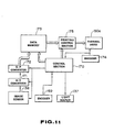
- encode plate 130 rotates according to the scanning operation and a traveling distance detection signal is supplied from traveling distance detection sensor 130 to control section 170.
- encoder 169 is constituted by encode plate 130 and traveling distance detection sensor 131.
- Control section 170 supplies a signal to drive light source 137, and supplies an image readout signal to image sensor 138 according to a signal from encoder 169.
- Image sensor 138 receives the image data.
- the image data is converted into binary data representing black and white by means of A/D converter section 171, converted into 4- or 8-bit parallel data and stored into data memory 173.
- encode plate 148 rotates according to the scanning distance and a printing timing signal is supplied from traveling distance detection sensor 149 to control section 170 and thermal head 150a.
- encoder 174 is constituted by encode plate 148 and traveling distance detection sensor 149.
- Control section 170 reads out image data from data memory 173 in response to the traveling distance detection signal and supplies the readout image data to printing control section 175.
- Printing control section 175 converts the image data to printing data.
- the printing data is supplied in synchronism with the traveling distance detection signal supplied from encoder 174 so as to selectively activate the heat generation elements of thermal head 150a.
- ink of ink tape 157 is transferred to paper and the image data read out by means of reading section 102 is copied on paper.
- reading section 102 of printing device 100 is set on paper. Then, rubber roller 124 of reading section 102 and rubber roller 128 of encoder unit 125 are set in contact with paper. At this time, reading guide recess portion 114 formed on the side portion of small casing 106 is aligned with the reading position of paper. If, in this condition, the operator scans printing device 100, rubber rollers 124 and 128 rotate on paper and the rotation of rubber roller 128 is transmitted to encode plate 130 via intermediate gear 129 so as to rotate encode plate 130 according to the scanning distance of casing member 101. When encode plate 130 rotates, the rotation angle thereof is detected by means of traveling distance detection sensor 131 which in turn supplies a detection signal to control section 170.
- Control section 170 supplies an image readout signal to image sensor 138 of reader unit 126.
- light source 137 of reader unit 126 is previously kept active to emit light, and the emitted light is applied to the reading position of paper via hole 108c of upper lid 108 and the reflected light is received by image sensor 138.
- the readout image data is converted into a binary data representing black and white by means of A/D converter section 171, converted into parallel data by means of S/P converter 172 and stored in data memory 173.
- openingiclosing lid 107 is removed from casing 105 and ink tape cassette 152 is mounted in casing 105. That is, cassette case 164 of ink tape cassette 152 is disposed between battery holding section 161 of cassette holding case 151 and head cover section 163 and tape take-up shaft 147 is inserted into take-up spool 165 of cassette case 164. At this time, part of ink tape 157 pulled out from ink cassette case 152 passes by the under surface of thermal head 150a and is received into ink cassette case 152.
- paper-contact roller 139 and paper-contact surface 151 a of cassette holding case 151 are set in contact with paper. Further, part of ink tape 157 pulled out from cassette case 164 is resiliently pressed against paper by means of thermal head 150a. If, in this condition, printing device 100 is scanned, paper-contact roller 139 rotates on paper.
- Paper-contact roller 139 is constituted by main rubber roller 139a and auxiliary rubber roller 139b. Main rubber roller 139a is disposed between metal plate 121 and roller mounting plate 153, and auxiliary rubber roller 139b is disposed behind metal plate 121.
- paper-contact roller 139 when paper-contact roller 139 is scanned in a direction perpendicular thereto, it smoothly rotates. However, if contact-paper roller 139 is scanned in an oblique direction, it hardly rotates and cannot rotate smoothly. As a result, printing device 100 tends to move in a direction perpendicular to paper-contact roller 139.
- Driving gear 154 rotates when paper-contact roller 139 rotates with the movement of printing device 100.
- the rotation of driving gear 154 is transmitted to fourth intermediate gear 143 of encode plate 148 by means of first to third intermediate gears 140 to 142, causing encode plate 148 to rotate.
- the rotation of fourth intermediate gear 148 is transmitted to tape take-up gear 145 via fifth intermediate gear 144 to rotate tape take-up shaft 147.
- takeup spool 165 of ink tape cassette 152 rotates. In this way, ink tape 157 wound around supply spool 166 is taken up by rotation of paper-contact roller 139, that is, the scanning operation of printing device 100.
- the rotation of encode plate 148 is detected by means of traveling distance detection sensor 149 which in turn supplies a detection signal to control section 170 and thermal head 150a as a printing timing signal.
- Control section 170 reads out image data from data memory 173 and supplies the same to printing control section 175. Then, the image data is converted into printing data by means of printing control section 175 and supplied to thermal head 150a.
- the heat generation elements arranged at the lower portion thereof are selectively activated to generate heat, causing heat transfer ink of ink tape 157 to be transferred to paper. As a result, the image data read out by means of reading section 102 is copied on paper.
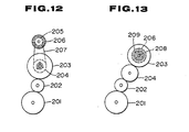
- the mechanism of transmitting rotation from the driving gear to the take-up gear and encode plate can be modified as shown in Figs. 12 and 13.
- Fig. 12 shows an example of the mechanism for transmitting rotation of driving gear 201 to take- up gear 203 and then to encode plate 206.
- intermediate gear 202 is arranged between driving gear 201 and take-up gear 203.
- Intermediate gear 204 which is rotated around the same central shaft as take-up gear 203 is mounted on the rear side of take-up gear 203.
- Take-up gear 203 has the above-described take-up shaft.
- intermediate gear 205 coaxially rotating with encode plate 206 is mounted on the rear side of encode plate 206.
- Rotation of intermediate gears 204 and 205 is transmitted by means of belt 207.
- rotation of driving gear 209 is transmitted to take-up gear 203 and intermediate gear 204 via intermediate gear 202.
- rotation of intermediate gear 204 is transmitted to intermediate gear 205 and encode plate 206 via belt 207.
- Fig. 13 shows an example in which take-up gear 203 and encode plate 206 are coaxially mounted.
- a hole is formed in a chassis (not shown) and bearing 209 is inserted into the hole and fixed.
- Supporting shaft 208 is rotatably mounted in a hole formed in bearing 209. The intermediate portion of supporting shaft 208 is supported by bearing 209 and supporting shaft 208 has a portion projecting from the front surface of the chassis and a portion projecting from the rear surface thereof.
- Take-up gear 203 is put on and fixed on that portion of supporting shaft 208 which projects from the front surface of the chassis. The fixation can be attained by screwing or caulking.
- Take-up gear 203 has a take-up shaft.
- encode plate 206 is fixed on that portion of supporting shaft 208 which projects from the rear surface of the chassis. That is, take-up gear 203, supporting shaft 208 and encode plate 206 are integrally rotated. With .this mechanism, rotation of driving gear 201 is transmitted to take-up gear 203 via intermediate gears 202 and 204. In this case, the rotation of take-up gear 203 is rotation of supporting shaft 208 and encode plate 206.
- each gear can be replaced by a rubber roller.
Landscapes
- Printers Characterized By Their Purpose (AREA)
- Impression-Transfer Materials And Handling Thereof (AREA)
- Record Information Processing For Printing (AREA)
Applications Claiming Priority (2)
| Application Number | Priority Date | Filing Date | Title |
|---|---|---|---|
| JP65853/88U | 1988-05-20 | ||
| JP6585388U JPH01169337U (de) | 1988-05-20 | 1988-05-20 |
Publications (2)
| Publication Number | Publication Date |
|---|---|
| EP0342697A2 true EP0342697A2 (de) | 1989-11-23 |
| EP0342697A3 EP0342697A3 (de) | 1990-04-25 |
Family
ID=13298987
Family Applications (1)
| Application Number | Title | Priority Date | Filing Date |
|---|---|---|---|
| EP89109062A Withdrawn EP0342697A3 (de) | 1988-05-20 | 1989-05-19 | Druckvorrichtung mit manueller Abtastung |
Country Status (2)
| Country | Link |
|---|---|
| EP (1) | EP0342697A3 (de) |
| JP (1) | JPH01169337U (de) |
Cited By (1)
| Publication number | Priority date | Publication date | Assignee | Title |
|---|---|---|---|---|
| WO1998021039A1 (fr) * | 1996-11-14 | 1998-05-22 | Aktsionernoe Obschestvo Zakrytogo Tipa 'paragraf-Interfeis' | Methode d'impression ligne par ligne et dispositif d'impression ligne par ligne |
Family Cites Families (2)
| Publication number | Priority date | Publication date | Assignee | Title |
|---|---|---|---|---|
| JPS6071275A (ja) * | 1983-09-28 | 1985-04-23 | Toshiba Corp | 画像出力装置 |
| DE3781591T2 (de) * | 1986-06-11 | 1993-01-07 | Casio Computer Co Ltd | Von hand bewegtes druckgeraet. |
-
1988
- 1988-05-20 JP JP6585388U patent/JPH01169337U/ja active Pending
-
1989
- 1989-05-19 EP EP89109062A patent/EP0342697A3/de not_active Withdrawn
Cited By (1)
| Publication number | Priority date | Publication date | Assignee | Title |
|---|---|---|---|---|
| WO1998021039A1 (fr) * | 1996-11-14 | 1998-05-22 | Aktsionernoe Obschestvo Zakrytogo Tipa 'paragraf-Interfeis' | Methode d'impression ligne par ligne et dispositif d'impression ligne par ligne |
Also Published As
| Publication number | Publication date |
|---|---|
| EP0342697A3 (de) | 1990-04-25 |
| JPH01169337U (de) | 1989-11-29 |
Similar Documents
| Publication | Publication Date | Title |
|---|---|---|
| EP0376326B1 (de) | Drucker für manuelle Abtastung | |
| US7038794B2 (en) | Image forming device which determines if the number of lines to be formed after converting image data exceeds a predetermined line count | |
| EP0270686B1 (de) | Prozessor für manuell abgetastete bilddaten | |
| EP0272633B1 (de) | Gerät für Hand-Bildabtastung | |
| US4851896A (en) | Manual sweeping apparatus | |
| US6375306B1 (en) | Image printing method and device | |
| US6798434B2 (en) | Printing device | |
| US6496275B1 (en) | Character printing method and device | |
| US5131090A (en) | Word processor with simplified character train designation for modifying fonts | |
| EP0351798B1 (de) | Handabtastdrucker | |
| EP0342697A2 (de) | Druckvorrichtung mit manueller Abtastung | |
| KR930002019B1 (ko) | 수동주사형 인자장치 | |
| US5264947A (en) | Copying device for producing a label | |
| JPH0958058A (ja) | プリンタ | |
| JP3577562B2 (ja) | 印刷装置における被印刷媒体の長さ設定装置 | |
| JPH05238097A (ja) | プリンタ | |
| JP2560419B2 (ja) | プリンタ | |
| JP2590874B2 (ja) | 文字データ処理装置 | |
| JP2501856Y2 (ja) | 手動走査式プリンタ | |
| JP2562555Y2 (ja) | ワードプロセッサ | |
| JP2501654Y2 (ja) | 印字機能を備えた電子機器 | |
| JPH088833Y2 (ja) | 小型文字印字装置 | |
| JPH088112Y2 (ja) | 小型印字装置 | |
| JPH088111Y2 (ja) | 小型印字装置 | |
| JP2021154688A (ja) | テープ印刷装置、テープ印刷システム、およびテープ印刷装置の制御方法 |
Legal Events
| Date | Code | Title | Description |
|---|---|---|---|
| PUAI | Public reference made under article 153(3) epc to a published international application that has entered the european phase |
Free format text: ORIGINAL CODE: 0009012 |
|
| AK | Designated contracting states |
Kind code of ref document: A2 Designated state(s): DE FR GB |
|
| PUAL | Search report despatched |
Free format text: ORIGINAL CODE: 0009013 |
|
| AK | Designated contracting states |
Kind code of ref document: A3 Designated state(s): DE FR GB |
|
| 17P | Request for examination filed |
Effective date: 19900803 |
|
| 17Q | First examination report despatched |
Effective date: 19920414 |
|
| STAA | Information on the status of an ep patent application or granted ep patent |
Free format text: STATUS: THE APPLICATION IS DEEMED TO BE WITHDRAWN |
|
| 18D | Application deemed to be withdrawn |
Effective date: 19920825 |