EP0342661B1 - Wärmedämmformkörper auf der Basis von verpresstem, mikroporösem Wärmedämmstoff mit einer Umhüllung auf der Basis von Metallen - Google Patents
Wärmedämmformkörper auf der Basis von verpresstem, mikroporösem Wärmedämmstoff mit einer Umhüllung auf der Basis von Metallen Download PDFInfo
- Publication number
- EP0342661B1 EP0342661B1 EP89108910A EP89108910A EP0342661B1 EP 0342661 B1 EP0342661 B1 EP 0342661B1 EP 89108910 A EP89108910 A EP 89108910A EP 89108910 A EP89108910 A EP 89108910A EP 0342661 B1 EP0342661 B1 EP 0342661B1
- Authority
- EP
- European Patent Office
- Prior art keywords
- weight
- thermal insulation
- metals
- microporous
- insulation material
- Prior art date
- Legal status (The legal status is an assumption and is not a legal conclusion. Google has not performed a legal analysis and makes no representation as to the accuracy of the status listed.)
- Expired - Lifetime
Links
- 229910052751 metal Inorganic materials 0.000 title claims abstract description 31
- 239000002184 metal Substances 0.000 title claims abstract description 31
- 150000002739 metals Chemical class 0.000 title claims abstract description 19
- 238000009413 insulation Methods 0.000 title abstract description 35
- 238000000576 coating method Methods 0.000 title abstract description 6
- 239000011248 coating agent Substances 0.000 title abstract description 5
- 239000007788 liquid Substances 0.000 claims abstract description 11
- 229910001092 metal group alloy Inorganic materials 0.000 claims abstract description 7
- 239000012774 insulation material Substances 0.000 claims description 30
- 239000000203 mixture Substances 0.000 claims description 11
- 229910044991 metal oxide Inorganic materials 0.000 claims description 10
- 150000004706 metal oxides Chemical class 0.000 claims description 10
- 238000000465 moulding Methods 0.000 claims description 8
- 239000011230 binding agent Substances 0.000 claims description 6
- 238000000034 method Methods 0.000 claims description 6
- 239000003605 opacifier Substances 0.000 claims description 6
- 239000002657 fibrous material Substances 0.000 claims description 5
- PNEYBMLMFCGWSK-UHFFFAOYSA-N Alumina Chemical compound [O-2].[O-2].[O-2].[Al+3].[Al+3] PNEYBMLMFCGWSK-UHFFFAOYSA-N 0.000 claims description 4
- 238000004512 die casting Methods 0.000 claims description 3
- 238000004519 manufacturing process Methods 0.000 claims description 3
- 238000002844 melting Methods 0.000 claims description 3
- 230000008018 melting Effects 0.000 claims description 3
- 235000012239 silicon dioxide Nutrition 0.000 claims description 2
- 239000000758 substrate Substances 0.000 claims 4
- RMAQACBXLXPBSY-UHFFFAOYSA-N silicic acid Chemical compound O[Si](O)(O)O RMAQACBXLXPBSY-UHFFFAOYSA-N 0.000 claims 1
- 229910052782 aluminium Inorganic materials 0.000 description 18
- XAGFODPZIPBFFR-UHFFFAOYSA-N aluminium Chemical compound [Al] XAGFODPZIPBFFR-UHFFFAOYSA-N 0.000 description 18
- 229910045601 alloy Inorganic materials 0.000 description 14
- 239000000956 alloy Substances 0.000 description 14
- VYPSYNLAJGMNEJ-UHFFFAOYSA-N Silicium dioxide Chemical compound O=[Si]=O VYPSYNLAJGMNEJ-UHFFFAOYSA-N 0.000 description 12
- 239000000463 material Substances 0.000 description 12
- XEEYBQQBJWHFJM-UHFFFAOYSA-N Iron Chemical compound [Fe] XEEYBQQBJWHFJM-UHFFFAOYSA-N 0.000 description 8
- PXHVJJICTQNCMI-UHFFFAOYSA-N Nickel Chemical compound [Ni] PXHVJJICTQNCMI-UHFFFAOYSA-N 0.000 description 8
- -1 basalt wool Substances 0.000 description 8
- 239000002585 base Substances 0.000 description 7
- OKTJSMMVPCPJKN-UHFFFAOYSA-N Carbon Chemical compound [C] OKTJSMMVPCPJKN-UHFFFAOYSA-N 0.000 description 6
- 230000006835 compression Effects 0.000 description 6
- 238000007906 compression Methods 0.000 description 6
- 239000011888 foil Substances 0.000 description 6
- 229910052710 silicon Inorganic materials 0.000 description 6
- XUIMIQQOPSSXEZ-UHFFFAOYSA-N Silicon Chemical compound [Si] XUIMIQQOPSSXEZ-UHFFFAOYSA-N 0.000 description 5
- 239000000853 adhesive Substances 0.000 description 5
- 230000001070 adhesive effect Effects 0.000 description 5
- 239000000835 fiber Substances 0.000 description 5
- 238000003475 lamination Methods 0.000 description 5
- 239000010703 silicon Substances 0.000 description 5
- 229910000838 Al alloy Inorganic materials 0.000 description 4
- PWHULOQIROXLJO-UHFFFAOYSA-N Manganese Chemical compound [Mn] PWHULOQIROXLJO-UHFFFAOYSA-N 0.000 description 4
- 244000089486 Phragmites australis subsp australis Species 0.000 description 4
- 229910000831 Steel Inorganic materials 0.000 description 4
- 229910052799 carbon Inorganic materials 0.000 description 4
- 238000005266 casting Methods 0.000 description 4
- 239000010949 copper Substances 0.000 description 4
- 229910052742 iron Inorganic materials 0.000 description 4
- 239000011777 magnesium Substances 0.000 description 4
- 229910052759 nickel Inorganic materials 0.000 description 4
- TWNQGVIAIRXVLR-UHFFFAOYSA-N oxo(oxoalumanyloxy)alumane Chemical compound O=[Al]O[Al]=O TWNQGVIAIRXVLR-UHFFFAOYSA-N 0.000 description 4
- 239000010959 steel Substances 0.000 description 4
- 239000004743 Polypropylene Substances 0.000 description 3
- GWEVSGVZZGPLCZ-UHFFFAOYSA-N Titan oxide Chemical compound O=[Ti]=O GWEVSGVZZGPLCZ-UHFFFAOYSA-N 0.000 description 3
- YKTSYUJCYHOUJP-UHFFFAOYSA-N [O--].[Al+3].[Al+3].[O-][Si]([O-])([O-])[O-] Chemical compound [O--].[Al+3].[Al+3].[O-][Si]([O-])([O-])[O-] YKTSYUJCYHOUJP-UHFFFAOYSA-N 0.000 description 3
- YDZQQRWRVYGNER-UHFFFAOYSA-N iron;titanium;trihydrate Chemical compound O.O.O.[Ti].[Fe] YDZQQRWRVYGNER-UHFFFAOYSA-N 0.000 description 3
- 229910052748 manganese Inorganic materials 0.000 description 3
- 239000011572 manganese Substances 0.000 description 3
- 239000011490 mineral wool Substances 0.000 description 3
- 229920001155 polypropylene Polymers 0.000 description 3
- 239000004576 sand Substances 0.000 description 3
- 239000000377 silicon dioxide Substances 0.000 description 3
- 239000010935 stainless steel Substances 0.000 description 3
- 229910001220 stainless steel Inorganic materials 0.000 description 3
- GFQYVLUOOAAOGM-UHFFFAOYSA-N zirconium(iv) silicate Chemical compound [Zr+4].[O-][Si]([O-])([O-])[O-] GFQYVLUOOAAOGM-UHFFFAOYSA-N 0.000 description 3
- 229910052580 B4C Inorganic materials 0.000 description 2
- 229910001018 Cast iron Inorganic materials 0.000 description 2
- RYGMFSIKBFXOCR-UHFFFAOYSA-N Copper Chemical compound [Cu] RYGMFSIKBFXOCR-UHFFFAOYSA-N 0.000 description 2
- 229910000881 Cu alloy Inorganic materials 0.000 description 2
- UQSXHKLRYXJYBZ-UHFFFAOYSA-N Iron oxide Chemical compound [Fe]=O UQSXHKLRYXJYBZ-UHFFFAOYSA-N 0.000 description 2
- FYYHWMGAXLPEAU-UHFFFAOYSA-N Magnesium Chemical compound [Mg] FYYHWMGAXLPEAU-UHFFFAOYSA-N 0.000 description 2
- 229910000861 Mg alloy Inorganic materials 0.000 description 2
- 239000004952 Polyamide Substances 0.000 description 2
- 229910000676 Si alloy Inorganic materials 0.000 description 2
- 229910000551 Silumin Inorganic materials 0.000 description 2
- ATJFFYVFTNAWJD-UHFFFAOYSA-N Tin Chemical compound [Sn] ATJFFYVFTNAWJD-UHFFFAOYSA-N 0.000 description 2
- RTAQQCXQSZGOHL-UHFFFAOYSA-N Titanium Chemical compound [Ti] RTAQQCXQSZGOHL-UHFFFAOYSA-N 0.000 description 2
- 239000004411 aluminium Substances 0.000 description 2
- QVQLCTNNEUAWMS-UHFFFAOYSA-N barium oxide Chemical compound [Ba]=O QVQLCTNNEUAWMS-UHFFFAOYSA-N 0.000 description 2
- INAHAJYZKVIDIZ-UHFFFAOYSA-N boron carbide Chemical compound B12B3B4C32B41 INAHAJYZKVIDIZ-UHFFFAOYSA-N 0.000 description 2
- 238000001816 cooling Methods 0.000 description 2
- 229910052802 copper Inorganic materials 0.000 description 2
- 238000005516 engineering process Methods 0.000 description 2
- 239000003365 glass fiber Substances 0.000 description 2
- 229910002804 graphite Inorganic materials 0.000 description 2
- 239000010439 graphite Substances 0.000 description 2
- 238000010438 heat treatment Methods 0.000 description 2
- 239000011810 insulating material Substances 0.000 description 2
- 239000011133 lead Substances 0.000 description 2
- 229910001338 liquidmetal Inorganic materials 0.000 description 2
- 229910052749 magnesium Inorganic materials 0.000 description 2
- NUJOXMJBOLGQSY-UHFFFAOYSA-N manganese dioxide Chemical compound O=[Mn]=O NUJOXMJBOLGQSY-UHFFFAOYSA-N 0.000 description 2
- WPBNNNQJVZRUHP-UHFFFAOYSA-L manganese(2+);methyl n-[[2-(methoxycarbonylcarbamothioylamino)phenyl]carbamothioyl]carbamate;n-[2-(sulfidocarbothioylamino)ethyl]carbamodithioate Chemical compound [Mn+2].[S-]C(=S)NCCNC([S-])=S.COC(=O)NC(=S)NC1=CC=CC=C1NC(=S)NC(=O)OC WPBNNNQJVZRUHP-UHFFFAOYSA-L 0.000 description 2
- 239000000155 melt Substances 0.000 description 2
- RVTZCBVAJQQJTK-UHFFFAOYSA-N oxygen(2-);zirconium(4+) Chemical compound [O-2].[O-2].[Zr+4] RVTZCBVAJQQJTK-UHFFFAOYSA-N 0.000 description 2
- 229920002647 polyamide Polymers 0.000 description 2
- 238000003825 pressing Methods 0.000 description 2
- 239000002510 pyrogen Substances 0.000 description 2
- 238000007493 shaping process Methods 0.000 description 2
- 229910021332 silicide Inorganic materials 0.000 description 2
- 229910052814 silicon oxide Inorganic materials 0.000 description 2
- 238000007711 solidification Methods 0.000 description 2
- 230000008023 solidification Effects 0.000 description 2
- 229910052719 titanium Inorganic materials 0.000 description 2
- 239000010936 titanium Substances 0.000 description 2
- 229910001928 zirconium oxide Inorganic materials 0.000 description 2
- 229910018134 Al-Mg Inorganic materials 0.000 description 1
- 229910018125 Al-Si Inorganic materials 0.000 description 1
- 229910018182 Al—Cu Inorganic materials 0.000 description 1
- 229910018467 Al—Mg Inorganic materials 0.000 description 1
- 229910018464 Al—Mg—Si Inorganic materials 0.000 description 1
- 229910018520 Al—Si Inorganic materials 0.000 description 1
- OYPRJOBELJOOCE-UHFFFAOYSA-N Calcium Chemical compound [Ca] OYPRJOBELJOOCE-UHFFFAOYSA-N 0.000 description 1
- VYZAMTAEIAYCRO-UHFFFAOYSA-N Chromium Chemical compound [Cr] VYZAMTAEIAYCRO-UHFFFAOYSA-N 0.000 description 1
- 229910001208 Crucible steel Inorganic materials 0.000 description 1
- 229910017818 Cu—Mg Inorganic materials 0.000 description 1
- 229910000640 Fe alloy Inorganic materials 0.000 description 1
- 229910001296 Malleable iron Inorganic materials 0.000 description 1
- 229910000914 Mn alloy Inorganic materials 0.000 description 1
- ZOKXTWBITQBERF-UHFFFAOYSA-N Molybdenum Chemical compound [Mo] ZOKXTWBITQBERF-UHFFFAOYSA-N 0.000 description 1
- 229910000978 Pb alloy Inorganic materials 0.000 description 1
- OAICVXFJPJFONN-UHFFFAOYSA-N Phosphorus Chemical compound [P] OAICVXFJPJFONN-UHFFFAOYSA-N 0.000 description 1
- 239000004698 Polyethylene Substances 0.000 description 1
- 229920002472 Starch Polymers 0.000 description 1
- NINIDFKCEFEMDL-UHFFFAOYSA-N Sulfur Chemical compound [S] NINIDFKCEFEMDL-UHFFFAOYSA-N 0.000 description 1
- HCHKCACWOHOZIP-UHFFFAOYSA-N Zinc Chemical compound [Zn] HCHKCACWOHOZIP-UHFFFAOYSA-N 0.000 description 1
- QCWXUUIWCKQGHC-UHFFFAOYSA-N Zirconium Chemical compound [Zr] QCWXUUIWCKQGHC-UHFFFAOYSA-N 0.000 description 1
- ULGYAEQHFNJYML-UHFFFAOYSA-N [AlH3].[Ca] Chemical compound [AlH3].[Ca] ULGYAEQHFNJYML-UHFFFAOYSA-N 0.000 description 1
- 238000005299 abrasion Methods 0.000 description 1
- 238000010521 absorption reaction Methods 0.000 description 1
- 239000003513 alkali Substances 0.000 description 1
- CSDREXVUYHZDNP-UHFFFAOYSA-N alumanylidynesilicon Chemical compound [Al].[Si] CSDREXVUYHZDNP-UHFFFAOYSA-N 0.000 description 1
- WPPDFTBPZNZZRP-UHFFFAOYSA-N aluminum copper Chemical compound [Al].[Cu] WPPDFTBPZNZZRP-UHFFFAOYSA-N 0.000 description 1
- SNAAJJQQZSMGQD-UHFFFAOYSA-N aluminum magnesium Chemical compound [Mg].[Al] SNAAJJQQZSMGQD-UHFFFAOYSA-N 0.000 description 1
- 229910052787 antimony Inorganic materials 0.000 description 1
- WATWJIUSRGPENY-UHFFFAOYSA-N antimony atom Chemical compound [Sb] WATWJIUSRGPENY-UHFFFAOYSA-N 0.000 description 1
- 239000010425 asbestos Substances 0.000 description 1
- 229910052797 bismuth Inorganic materials 0.000 description 1
- JCXGWMGPZLAOME-UHFFFAOYSA-N bismuth atom Chemical compound [Bi] JCXGWMGPZLAOME-UHFFFAOYSA-N 0.000 description 1
- 229910052793 cadmium Inorganic materials 0.000 description 1
- BDOSMKKIYDKNTQ-UHFFFAOYSA-N cadmium atom Chemical compound [Cd] BDOSMKKIYDKNTQ-UHFFFAOYSA-N 0.000 description 1
- 229910052791 calcium Inorganic materials 0.000 description 1
- 239000011575 calcium Substances 0.000 description 1
- BRPQOXSCLDDYGP-UHFFFAOYSA-N calcium oxide Chemical compound [O-2].[Ca+2] BRPQOXSCLDDYGP-UHFFFAOYSA-N 0.000 description 1
- 239000000292 calcium oxide Substances 0.000 description 1
- ODINCKMPIJJUCX-UHFFFAOYSA-N calcium oxide Inorganic materials [Ca]=O ODINCKMPIJJUCX-UHFFFAOYSA-N 0.000 description 1
- 229910021346 calcium silicide Inorganic materials 0.000 description 1
- 239000001913 cellulose Substances 0.000 description 1
- 229920002678 cellulose Polymers 0.000 description 1
- 239000000919 ceramic Substances 0.000 description 1
- 229910052804 chromium Inorganic materials 0.000 description 1
- 239000011651 chromium Substances 0.000 description 1
- 229940090961 chromium dioxide Drugs 0.000 description 1
- IAQWMWUKBQPOIY-UHFFFAOYSA-N chromium(4+);oxygen(2-) Chemical compound [O-2].[O-2].[Cr+4] IAQWMWUKBQPOIY-UHFFFAOYSA-N 0.000 description 1
- AYTAKQFHWFYBMA-UHFFFAOYSA-N chromium(IV) oxide Inorganic materials O=[Cr]=O AYTAKQFHWFYBMA-UHFFFAOYSA-N 0.000 description 1
- 238000005253 cladding Methods 0.000 description 1
- 239000002131 composite material Substances 0.000 description 1
- 239000000470 constituent Substances 0.000 description 1
- 238000010276 construction Methods 0.000 description 1
- 230000007123 defense Effects 0.000 description 1
- 238000007872 degassing Methods 0.000 description 1
- 238000000280 densification Methods 0.000 description 1
- 238000004049 embossing Methods 0.000 description 1
- 239000004744 fabric Substances 0.000 description 1
- 229910021485 fumed silica Inorganic materials 0.000 description 1
- 229910000743 fusible alloy Inorganic materials 0.000 description 1
- 239000007789 gas Substances 0.000 description 1
- 239000011491 glass wool Substances 0.000 description 1
- 239000012212 insulator Substances 0.000 description 1
- DALUDRGQOYMVLD-UHFFFAOYSA-N iron manganese Chemical compound [Mn].[Fe] DALUDRGQOYMVLD-UHFFFAOYSA-N 0.000 description 1
- 230000001788 irregular Effects 0.000 description 1
- 239000000395 magnesium oxide Substances 0.000 description 1
- CPLXHLVBOLITMK-UHFFFAOYSA-N magnesium oxide Inorganic materials [Mg]=O CPLXHLVBOLITMK-UHFFFAOYSA-N 0.000 description 1
- AXZKOIWUVFPNLO-UHFFFAOYSA-N magnesium;oxygen(2-) Chemical compound [O-2].[Mg+2] AXZKOIWUVFPNLO-UHFFFAOYSA-N 0.000 description 1
- 238000005259 measurement Methods 0.000 description 1
- 229910052750 molybdenum Inorganic materials 0.000 description 1
- 239000011733 molybdenum Substances 0.000 description 1
- 239000004745 nonwoven fabric Substances 0.000 description 1
- 229910052698 phosphorus Inorganic materials 0.000 description 1
- 239000011574 phosphorus Substances 0.000 description 1
- 230000000704 physical effect Effects 0.000 description 1
- 229920000573 polyethylene Polymers 0.000 description 1
- 235000019353 potassium silicate Nutrition 0.000 description 1
- 230000000717 retained effect Effects 0.000 description 1
- 229910052895 riebeckite Inorganic materials 0.000 description 1
- 238000007789 sealing Methods 0.000 description 1
- 238000000926 separation method Methods 0.000 description 1
- 230000035939 shock Effects 0.000 description 1
- HBMJWWWQQXIZIP-UHFFFAOYSA-N silicon carbide Chemical compound [Si+]#[C-] HBMJWWWQQXIZIP-UHFFFAOYSA-N 0.000 description 1
- 229910010271 silicon carbide Inorganic materials 0.000 description 1
- NTHWMYGWWRZVTN-UHFFFAOYSA-N sodium silicate Chemical compound [Na+].[Na+].[O-][Si]([O-])=O NTHWMYGWWRZVTN-UHFFFAOYSA-N 0.000 description 1
- 239000007787 solid Substances 0.000 description 1
- 230000006641 stabilisation Effects 0.000 description 1
- 238000011105 stabilization Methods 0.000 description 1
- 239000008107 starch Substances 0.000 description 1
- 235000019698 starch Nutrition 0.000 description 1
- 239000011593 sulfur Substances 0.000 description 1
- 229910052717 sulfur Inorganic materials 0.000 description 1
- 239000004408 titanium dioxide Substances 0.000 description 1
- OGIDPMRJRNCKJF-UHFFFAOYSA-N titanium oxide Inorganic materials [Ti]=O OGIDPMRJRNCKJF-UHFFFAOYSA-N 0.000 description 1
- 229910052720 vanadium Inorganic materials 0.000 description 1
- LEONUFNNVUYDNQ-UHFFFAOYSA-N vanadium atom Chemical compound [V] LEONUFNNVUYDNQ-UHFFFAOYSA-N 0.000 description 1
- XLYOFNOQVPJJNP-UHFFFAOYSA-N water Substances O XLYOFNOQVPJJNP-UHFFFAOYSA-N 0.000 description 1
- 229910000634 wood's metal Inorganic materials 0.000 description 1
- 210000002268 wool Anatomy 0.000 description 1
- 229910052725 zinc Inorganic materials 0.000 description 1
- 239000011701 zinc Substances 0.000 description 1
- 229910052726 zirconium Inorganic materials 0.000 description 1
Images

Classifications
-
- B—PERFORMING OPERATIONS; TRANSPORTING
- B22—CASTING; POWDER METALLURGY
- B22D—CASTING OF METALS; CASTING OF OTHER SUBSTANCES BY THE SAME PROCESSES OR DEVICES
- B22D19/00—Casting in, on, or around objects which form part of the product
- B22D19/08—Casting in, on, or around objects which form part of the product for building-up linings or coverings, e.g. of anti-frictional metal
-
- F—MECHANICAL ENGINEERING; LIGHTING; HEATING; WEAPONS; BLASTING
- F16—ENGINEERING ELEMENTS AND UNITS; GENERAL MEASURES FOR PRODUCING AND MAINTAINING EFFECTIVE FUNCTIONING OF MACHINES OR INSTALLATIONS; THERMAL INSULATION IN GENERAL
- F16L—PIPES; JOINTS OR FITTINGS FOR PIPES; SUPPORTS FOR PIPES, CABLES OR PROTECTIVE TUBING; MEANS FOR THERMAL INSULATION IN GENERAL
- F16L59/00—Thermal insulation in general
- F16L59/04—Arrangements using dry fillers, e.g. using slag wool
-
- F—MECHANICAL ENGINEERING; LIGHTING; HEATING; WEAPONS; BLASTING
- F16—ENGINEERING ELEMENTS AND UNITS; GENERAL MEASURES FOR PRODUCING AND MAINTAINING EFFECTIVE FUNCTIONING OF MACHINES OR INSTALLATIONS; THERMAL INSULATION IN GENERAL
- F16L—PIPES; JOINTS OR FITTINGS FOR PIPES; SUPPORTS FOR PIPES, CABLES OR PROTECTIVE TUBING; MEANS FOR THERMAL INSULATION IN GENERAL
- F16L59/00—Thermal insulation in general
- F16L59/14—Arrangements for the insulation of pipes or pipe systems
Definitions
- the invention relates to thermal insulation molded articles on the basis of pressed, microporous thermal insulation material with an envelope based on metals.
- thermal insulation materials based on compressed, microporous thermal insulation material must be provided with protection against mechanical stresses, such as vibrations, vibrations, shocks or impacts, at least on the cold side, since the thermal insulation materials themselves have low strength.
- Thermal insulation molded articles of the type in question with coatings based on metals are known from EP-A-59860 or the corresponding US-A-4447345 and EP-A-205155, where thermal insulation materials with stamped, drawn or otherwise shaped metal sheets as Envelopes are provided.
- the covering cannot be made so strong that optimal protection of the molded thermal insulation body is guaranteed, the shaping cannot be carried out to the desired extent or the metal covering cannot be designed in this way, that the cavities between the casing and the thermal insulation material are minimized in the sense of optimal thermal insulation.
- the object of the invention is to provide thermal insulation molded articles based on microporous, pressed thermal insulation material with an at least one-sided coating based on metals, which ensures optimal protection of the thermal insulation material against mechanical stresses and the voids between the casing and the thermal insulation material in the sense of optimal thermal insulation minimized.
- the invention relates to molded thermal bodies on the basis of microporous, pressed thermal insulation material with an at least one-sided coating based on metals obtainable by applying metals or metal alloys in a liquid state to a base body based on microporous, compressed thermal insulation material.
- the metal envelops the base body in liquid form and only then hardens, there are no restrictions in the thickness and also in the shape of the envelope. This opens up a wide range of applications in motors, units and pipe insulation that were not possible according to the state of the art. Furthermore, the embedding of the heat-insulating molded body in the liquid metal minimizes the voids between the casing and the heat-insulating material.
- the molded thermal insulation articles according to the invention can represent irregular and / or different geometric shapes, with constant physical properties being guaranteed over the entire body.
- the heat-insulating molded articles according to the invention are surrounded on at least one side, mostly on the cold side of the heat-insulating molded article, by metal which was applied in the liquid state.
- the thermal insulation molded body can also be encapsulated by metal on all sides.
- the object to be insulated by the thermal insulation molded body according to the invention can be provided with the heat-insulating base body before the casting process, in which case only the free sides of the thermal insulation material are then encapsulated.
- it can also be provided with prefabricated molded thermal insulation bodies according to the invention, the molded body being able to be cast on all sides, but mostly the sides facing the object to be insulated remain free.
- finely divided metal oxide examples include pyrogenically produced silicas, including arcing silicas, low-alkali precipitated silicas, similarly produced aluminum oxide, titanium oxide and zirconium oxide, and mixtures thereof. Pyrogenically generated silica, aluminum oxide or a mixture thereof is preferably used.
- the finely divided metal oxides have specific surfaces of preferably 50-700 m2 / g, in particular 70-400 m2 / g.
- opacifiers are ilmenite, titanium dioxide, silicon carbide, iron-II-iron-III mixed oxide, chromium dioxide, zirconium oxide, manganese dioxide, iron oxide, silicon dioxide, aluminum oxide and zirconium silicate, and mixtures thereof.
- Ilmenite and zirconium silicate are preferably used.
- the opacifiers advantageously have an absorption maximum in the infrared range between 1.5 and 10 ⁇ m.
- fiber material examples include glass wool, rock wool, basalt wool, slag wool, ceramic fibers, such as those obtained from melts of aluminum and / or silicon oxide, and asbestos fibers, and mixtures thereof. Fibers obtained from the melt of aluminum and / or silicon oxide are preferably used.
- binders known to be used in microporous, compressed thermal insulation materials can be used as inorganic binders.
- examples of such binders are for example disclosed in EP-A-29227.
- Borides of aluminum, titanium, zirconium, calcium, silicides such as calcium silicide and calcium aluminum silicide, in particular boron carbide, are preferably used.
- examples of further constituents are basic oxides, in particular magnesium oxide, calcium oxide or barium oxide.
- the metals or metal alloys used have a melting point of preferably 300 to 1500 ° C., in particular 500 to 1200 ° C.
- metals or their alloys are aluminum and its alloys with magnesium, silicon, copper, manganese and nickel; Copper, as well as its alloys with zinc, lead, silicon, iron and nickel, or iron, as well as its alloys with manganese and silicon, which have a carbon content of 2-4% and a controlled phosphorus and sulfur content.
- the iron alloys mentioned are known to the person skilled in the art under the terms malleable cast iron, cast iron with lamellar graphite and cast iron with spheroidal graphite.
- aluminum alloys are silumin Al-Si, an aluminum-silicon alloy with up to 14% by weight of silicon, silumin Al-Mg-Si, an aluminum-magnesium-silicon alloy with up to 1% by weight of Mg and up to 14% by weight.
- % Si aluminum alloy Al-Mg, an aluminum-magnesium alloy with up to 5% by weight Mg and 0.2% by weight Si and 0.7-0.5% by weight manganese
- aluminum alloy Al-Cu an aluminum-copper alloy with 6-14% by weight Cu
- aluminum alloy Al-Ni-Cu-Mg an aluminum-nickel-copper-magnesium alloy with 4-5% by weight Cu, 1-2% by weight magnesium and 1.5-2.5 wt% nickel.
- metals or their alloys are iron-containing cast steel alloys with a carbon content of less than 2% by weight with different proportions of alloy elements known to the person skilled in the art, such as manganese, silicon, nickel, chromium, molybdenum, vanadium and titanium, and letter alloys such as Lead alloys with up to 30% by weight antimony and 5% by weight tin or the alloy known under the term Wood's metal with 25% by weight lead, 30% by weight bismuth, 12.5% by weight Tin and 12.5% by weight cadmium.
- Typical for letter alloys is a low melting point, good flowability, high strength, in particular abrasion resistance, and the property that their density increases during solidification, which leads to particularly good mold filling behavior.
- the choice of the preferred metals or their alloys depends on the respective application, the wear resistance is the focus, preferably iron-containing alloys, letter alloys for low-melting alloys and aluminum or letter alloys for high flowability.
- the gases enclosed in the bed should be able to escape during pre-compression or compression. Therefore, the compression and compression is preferably carried out with the application of Vacuum. Degassing can also take place before compression or compression.
- the prefabricated base body can optionally be provided at least on one side with a lamination in a manner known per se in order to increase the flexibility of the base body.
- a lamination in a manner known per se in order to increase the flexibility of the base body.
- all materials can be used as lamination with which thermal insulation molded articles of the type according to the invention have previously been laminated. These are preferably nonwovens or fabrics made of aluminum silicate, glass fiber, rock wool, cellulose, in particular metal foils such as aluminum foil, stainless steel foil and others.
- the connection between the lamination material and the pressed thermal insulation material can be adhesive or non-adhesive.
- thermal insulation material In the case of materials such as glass fiber and the like, there is sufficient mechanical interlocking of the thermal insulation material with the lamination material by applying pressure and without using an adhesive, in particular if the lamination material is pressed with the loose bed of thermal insulation material or with pre-compressed thermal insulation material at the above-mentioned final pressures.
- inorganic adhesives such as, for example, silica sols or water glass, or known organic adhesives can also be used.
- Molded heat-insulating articles with a sheath according to the older patent application EP-A-0 315 169 (priority: 05.11.87 DE 3737459; publication date: 10.05.89) can also be used.
- thermal insulation molded bodies are described with a sheath, which are characterized in that a molding from a base body provided with a deep-drawable sheathing based on pressed, microporous thermal insulation material, the pressure inside the sheath being reduced to up to 10 ⁇ 6 bar, at pressures in Range from 1 t / m2 to 1000 t / m2. Since there is always a negative pressure inside the casing, those used there must be Enclosures should be gastight and completely enclose the body. Furthermore, only sheaths are used there that are deep-drawable, that is, in which no material separation occurs due to the decrease in diameter during the shaping process.
- metals or metal alloys in a liquid state are applied to these previously described basic bodies based on compressed, microporous thermal insulation material, preferably the basic body being surrounded by a mold and the distance between the inner mold wall and the main body of the starch to be achieved corresponds to the metal casing.
- the liquid can be introduced into the mold (chill mold) by simple pouring in, but also under pressure (die casting).
- Mold sand can be used as the mold material, in particular for casting with core, metals or cooled light metals, which are usually cooled with water. Methods have proven to be particularly advantageous proven, in which metallic permanent molds are used.
- thermal insulation molded parts according to the invention are used wherever it is necessary to effectively isolate thermally stressed parts, in particular when the temperature and space conditions make a highly insulating thermal insulator absolutely necessary.
- Possible uses of the thermal insulation molded articles according to the invention are, for example, the insulation of exhaust manifolds, front pipes, and special heat shields and engine insulations in the area of cylinders and port liners in the motor vehicle sector.
- Other areas in which the thermal insulation molded article according to the invention can be used are aviation, measurement and control technology, defense technology and plant construction.
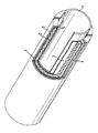
- a section through the insulation arrangement showed the insulation material unchanged in the structure.
- the insulation thickness remained unchanged at 5 mm.
- This gap (5) is of crucial importance for certain applications in the engine area, such as in the case of manifolds. If sheet metal elbows are insulated, movement compensation must be possible for the inner and outer shell. So far, this has been solved by a load-bearing outer shell to which the inner shell was welded in the area of the inlet connection. The inner shell was able to compensate for the thermal expansion at least in the vertical direction.
- a disadvantage of this system is that the insulation is affected by the movements.
- insulation arrangement obtained according to the example - load-bearing pipe insulation, cast aluminum outer shell - when the pipe is tempered for the first time, a tiny gap of 300 ⁇ m is created between the aluminum skin and the elbow. As a result, the pipe can now expand in the axial direction, in a direction of movement that stresses the insulation significantly less. The insulation swings around the pipe.
Landscapes
- Engineering & Computer Science (AREA)
- General Engineering & Computer Science (AREA)
- Mechanical Engineering (AREA)
- Thermal Insulation (AREA)
- Laminated Bodies (AREA)
Priority Applications (1)
| Application Number | Priority Date | Filing Date | Title |
|---|---|---|---|
| AT89108910T ATE79805T1 (de) | 1988-05-18 | 1989-05-18 | Waermedaemmformkoerper auf der basis von verpresstem, mikroporoesem waermedaemmstoff mit einer umhuellung auf der basis von metallen. |
Applications Claiming Priority (2)
| Application Number | Priority Date | Filing Date | Title |
|---|---|---|---|
| DE3816979A DE3816979A1 (de) | 1988-05-18 | 1988-05-18 | Waermedaemmformkoerper auf der basis von verpresstem, mikroporoesem waermedaemmstoff mit einer umhuellung auf der basis von metallen |
| DE3816979 | 1988-05-18 |
Publications (2)
| Publication Number | Publication Date |
|---|---|
| EP0342661A1 EP0342661A1 (de) | 1989-11-23 |
| EP0342661B1 true EP0342661B1 (de) | 1992-08-26 |
Family
ID=6354645
Family Applications (1)
| Application Number | Title | Priority Date | Filing Date |
|---|---|---|---|
| EP89108910A Expired - Lifetime EP0342661B1 (de) | 1988-05-18 | 1989-05-18 | Wärmedämmformkörper auf der Basis von verpresstem, mikroporösem Wärmedämmstoff mit einer Umhüllung auf der Basis von Metallen |
Country Status (5)
| Country | Link |
|---|---|
| EP (1) | EP0342661B1 (es) |
| JP (1) | JPH0238392A (es) |
| AT (1) | ATE79805T1 (es) |
| DE (2) | DE3816979A1 (es) |
| ES (1) | ES2034490T3 (es) |
Cited By (1)
| Publication number | Priority date | Publication date | Assignee | Title |
|---|---|---|---|---|
| US7011115B1 (en) | 1999-05-27 | 2006-03-14 | Saipem, S.P.A. | Insulated pipe structure and methods of making such structures |
Families Citing this family (14)
| Publication number | Priority date | Publication date | Assignee | Title |
|---|---|---|---|---|
| DE3922636C1 (en) * | 1989-07-10 | 1991-01-24 | Goetze Ag, 5093 Burscheid, De | Thermally shielding ICE construction parts - using device comprising metal shield or film coated with heat insulation material |
| DE4015342A1 (de) * | 1990-05-12 | 1991-11-14 | Karl Heinz Vahlbrauk | Installationswand |
| DE4019870A1 (de) * | 1990-06-22 | 1992-01-09 | Degussa | Vakuumisolationspanel mit asymmetrischem aufbau |
| DE4022506A1 (de) * | 1990-07-14 | 1992-01-16 | Hoermansdoerfer Gerd | Thermische daemmung |
| DE4023119A1 (de) * | 1990-07-20 | 1992-02-06 | Porotherm Daemmstoffe Gmbh | Produkte begleitender datentraeger |
| DE29513519U1 (de) * | 1995-08-23 | 1995-11-30 | KKW Kulmbacher Klimageräte-Werk GmbH, 95326 Kulmbach | Wärmedämmung |
| DE19859084C1 (de) * | 1998-12-19 | 2000-05-11 | Redco Nv | Mikroporöser Wärmedämmkörper |
| DE59908776D1 (de) * | 1998-12-19 | 2004-04-08 | Promat Internat N V | Mikroporöser wärmedämmkörper |
| DE10007844A1 (de) | 2000-02-21 | 2001-08-23 | Rheinhold & Mahla Ag | Gehäuse einer Behandlungseinrichtung für gegenüber Umgebungstemperatur heiße Gase |
| DE50009283D1 (de) * | 2000-05-31 | 2005-02-24 | Tyk Europ Gmbh | Verfahren zum Beschichten von Ausgüssen, Giessrohren, Giessstrahlschutzrohren und dergleichen Werkstücken zum Vergiessen und Überführen von Schmelzen |
| GB0323054D0 (en) * | 2003-10-02 | 2003-11-05 | Microtherm Int Ltd | Microporous thermal insulation material |
| FR2881505B1 (fr) * | 2005-02-01 | 2007-04-27 | Faurecia Sys Echappement | Procede pour fabriquer une conduite isolee, notamment pour ligne d'echappement de vehicule automobile et conduite obtenue |
| US9790836B2 (en) | 2012-11-20 | 2017-10-17 | Tenneco Automotive Operating Company, Inc. | Loose-fill insulation exhaust gas treatment device and methods of manufacturing |
| CN109111243B (zh) * | 2018-09-20 | 2020-12-11 | 界首永恩机电科技有限公司 | 一种陶瓷工艺品表面喷施复合铜粉末的方法 |
Family Cites Families (12)
| Publication number | Priority date | Publication date | Assignee | Title |
|---|---|---|---|---|
| JPS5858311B2 (ja) * | 1976-09-02 | 1983-12-24 | トヨタ自動車株式会社 | セラミック鋳ぐるみ鋳物の製造方法 |
| DE3108816A1 (de) * | 1981-03-09 | 1982-09-30 | Grünzweig + Hartmann und Glasfaser AG, 6700 Ludwigshafen | Waermedaemmender pressstoff auf der basis von aus der flammenhydrolyse gewonnenem mikroporoesem oxidaerogel, sowie verfahren zu seiner herstellung, eine daraus hergestellte folie und ein damit hergestelltes kaschiertes waermedaemmelement |
| DE3318589A1 (de) * | 1983-05-21 | 1984-11-22 | Philips Patentverwaltung Gmbh, 2000 Hamburg | Verfahren zur herstellung von optischen wellenleitern |
| JPS6037260A (ja) * | 1983-08-09 | 1985-02-26 | Nippon Steel Corp | セラミツクス複合鋳物材の製造方法 |
| JPS6046237A (ja) * | 1983-08-23 | 1985-03-13 | 株式会社クボタ | 円筒状セラミックス・金属複合材の製造方法 |
| JPS60155588A (ja) * | 1984-01-25 | 1985-08-15 | 株式会社日立製作所 | ガス雰囲気下で使用される耐火物部材 |
| DE3418637A1 (de) * | 1984-05-18 | 1985-11-21 | Wacker-Chemie GmbH, 8000 München | Waermedaemmformkoerper mit umhuellung |
| DE3520955A1 (de) * | 1985-06-12 | 1986-12-18 | Wacker-Chemie GmbH, 8000 München | Katalysatorauspuff mit waermedaemmung |
| DE3530924A1 (de) * | 1985-08-29 | 1987-03-12 | Alcan Aluminiumwerke | Hitzebestaendiges bauteil und verfahren zu dessen herstellung |
| JPS63318025A (ja) * | 1987-06-22 | 1988-12-26 | Asahi Chem Ind Co Ltd | 金属一酸化物複合材料の製造方法 |
| JPS6460912A (en) * | 1987-09-01 | 1989-03-08 | Matsushita Electric Industrial Co Ltd | Ceramic superconductor and its manufacture |
| DE3737459A1 (de) * | 1987-11-05 | 1989-05-18 | Wacker Chemie Gmbh | Waermedaemmformkoerper mit umhuellung auf basis von verpresstem, mikroporoesem waermedaemmstoff |
-
1988
- 1988-05-18 DE DE3816979A patent/DE3816979A1/de not_active Withdrawn
-
1989
- 1989-05-16 JP JP1120606A patent/JPH0238392A/ja active Pending
- 1989-05-18 DE DE8989108910T patent/DE58902120D1/de not_active Expired - Lifetime
- 1989-05-18 EP EP89108910A patent/EP0342661B1/de not_active Expired - Lifetime
- 1989-05-18 AT AT89108910T patent/ATE79805T1/de not_active IP Right Cessation
- 1989-05-18 ES ES198989108910T patent/ES2034490T3/es not_active Expired - Lifetime
Cited By (1)
| Publication number | Priority date | Publication date | Assignee | Title |
|---|---|---|---|---|
| US7011115B1 (en) | 1999-05-27 | 2006-03-14 | Saipem, S.P.A. | Insulated pipe structure and methods of making such structures |
Also Published As
| Publication number | Publication date |
|---|---|
| ES2034490T3 (es) | 1993-04-01 |
| ATE79805T1 (de) | 1992-09-15 |
| DE3816979A1 (de) | 1989-11-30 |
| DE58902120D1 (de) | 1992-10-01 |
| JPH0238392A (ja) | 1990-02-07 |
| EP0342661A1 (de) | 1989-11-23 |
Similar Documents
| Publication | Publication Date | Title |
|---|---|---|
| EP0342661B1 (de) | Wärmedämmformkörper auf der Basis von verpresstem, mikroporösem Wärmedämmstoff mit einer Umhüllung auf der Basis von Metallen | |
| EP0164006B1 (de) | Wärmedämmformkörper mit Umhüllung | |
| EP0968151B1 (de) | Schmelzinfiltrierte faserverstärkte verbundkeramik | |
| DE68920263T2 (de) | Verfahren zur Herstellung von einem durch Keramik verstärkten Verbundkörperelement für Kraftfahrzeuge. | |
| EP0850206B1 (de) | Aerogel- und klebstoffhaltiges verbundmaterial, verfahren zu seiner herstellung sowie seine verwendung | |
| DE68920267T2 (de) | Verfahren zur Herstellung von einem durch Keramik verstärkten Verbundmaterial. | |
| EP1140729B1 (de) | Mikroporöser wärmedämmkörper | |
| DE3033515A1 (de) | Waermedaemmplatte | |
| DE2146031A1 (de) | Giessform und schalenfoermige trichter fuer giessformen | |
| DE19706926A1 (de) | Verfahren zur Herstellung von Keramik-Metall-Verbundkörpern, Keramik-Metall-Verbundkörper und deren Verwendung | |
| DE2702602A1 (de) | Formwerkzeuge zum formen von formbaren materialien sowie verfahren zur herstellung solcher formwerkzeuge | |
| DE69403364T2 (de) | Verfahren zum Herstellen von Wärmeschutzelementen, insbesondere für Raumfahrzeuge | |
| DE3829039A1 (de) | An ein metallisches bauteil gebundener keramischer belag | |
| AT391107B (de) | Verbundbauteil, bestehend aus mindestens zwei teilen aus unterschiedlichen fasermaterialien | |
| EP2164818B1 (de) | Keramische brandschutzplatte und verfahren zu deren herstellung | |
| DE2848110A1 (de) | Auspuffleitung fuer verbrennungskraftmaschinen | |
| EP0315169B1 (de) | Wärmedämmformkörper mit Umhüllung | |
| DE3724995C2 (es) | ||
| DE2707835A1 (de) | Keramikgegenstaende und verfahren zu deren herstellung | |
| US4312398A (en) | Method of forming fiber and metal composite structures | |
| DE102004030780A1 (de) | Verbundwerkstoff und Verfahren zu seiner Herstellung | |
| DE102016112042B4 (de) | Wärmedämmender, feuerfester Formkörper, insbesondere Platte, und Verfahren zu dessen Herstellung und dessen Verwendung | |
| EP3478431B1 (de) | Verwendung eines wärmedämmenden formkörpers zur isolation von metallschmelzen gegenüber der atmosphäre oder einem metallurgischen gefäss | |
| EP0101911A2 (de) | Temperaturschockbeständige keramische Auskleidungen | |
| DE4003809C2 (es) |
Legal Events
| Date | Code | Title | Description |
|---|---|---|---|
| PUAI | Public reference made under article 153(3) epc to a published international application that has entered the european phase |
Free format text: ORIGINAL CODE: 0009012 |
|
| 17P | Request for examination filed |
Effective date: 19890518 |
|
| AK | Designated contracting states |
Kind code of ref document: A1 Designated state(s): AT BE DE ES FR GB IT NL SE |
|
| 17Q | First examination report despatched |
Effective date: 19910715 |
|
| RAP1 | Party data changed (applicant data changed or rights of an application transferred) |
Owner name: WACKER-CHEMIE GMBH |
|
| ITF | It: translation for a ep patent filed | ||
| GRAA | (expected) grant |
Free format text: ORIGINAL CODE: 0009210 |
|
| AK | Designated contracting states |
Kind code of ref document: B1 Designated state(s): AT BE DE ES FR GB IT NL SE |
|
| REF | Corresponds to: |
Ref document number: 79805 Country of ref document: AT Date of ref document: 19920915 Kind code of ref document: T |
|
| REF | Corresponds to: |
Ref document number: 58902120 Country of ref document: DE Date of ref document: 19921001 |
|
| ET | Fr: translation filed | ||
| GBT | Gb: translation of ep patent filed (gb section 77(6)(a)/1977) | ||
| REG | Reference to a national code |
Ref country code: ES Ref legal event code: FG2A Ref document number: 2034490 Country of ref document: ES Kind code of ref document: T3 |
|
| PLBE | No opposition filed within time limit |
Free format text: ORIGINAL CODE: 0009261 |
|
| STAA | Information on the status of an ep patent application or granted ep patent |
Free format text: STATUS: NO OPPOSITION FILED WITHIN TIME LIMIT |
|
| 26N | No opposition filed | ||
| EAL | Se: european patent in force in sweden |
Ref document number: 89108910.4 |
|
| PGFP | Annual fee paid to national office [announced via postgrant information from national office to epo] |
Ref country code: FR Payment date: 19960415 Year of fee payment: 8 |
|
| PGFP | Annual fee paid to national office [announced via postgrant information from national office to epo] |
Ref country code: SE Payment date: 19960417 Year of fee payment: 8 Ref country code: NL Payment date: 19960417 Year of fee payment: 8 |
|
| PGFP | Annual fee paid to national office [announced via postgrant information from national office to epo] |
Ref country code: AT Payment date: 19960419 Year of fee payment: 8 |
|
| PGFP | Annual fee paid to national office [announced via postgrant information from national office to epo] |
Ref country code: GB Payment date: 19960425 Year of fee payment: 8 |
|
| PGFP | Annual fee paid to national office [announced via postgrant information from national office to epo] |
Ref country code: BE Payment date: 19960430 Year of fee payment: 8 |
|
| PGFP | Annual fee paid to national office [announced via postgrant information from national office to epo] |
Ref country code: ES Payment date: 19960514 Year of fee payment: 8 |
|
| PGFP | Annual fee paid to national office [announced via postgrant information from national office to epo] |
Ref country code: DE Payment date: 19960613 Year of fee payment: 8 |
|
| PG25 | Lapsed in a contracting state [announced via postgrant information from national office to epo] |
Ref country code: GB Effective date: 19970518 Ref country code: AT Effective date: 19970518 |
|
| PG25 | Lapsed in a contracting state [announced via postgrant information from national office to epo] |
Ref country code: SE Effective date: 19970519 Ref country code: ES Free format text: LAPSE BECAUSE OF NON-PAYMENT OF DUE FEES Effective date: 19970519 |
|
| PG25 | Lapsed in a contracting state [announced via postgrant information from national office to epo] |
Ref country code: BE Effective date: 19970531 |
|
| BERE | Be: lapsed |
Owner name: WACKER-CHEMIE G.M.B.H. Effective date: 19970531 |
|
| PG25 | Lapsed in a contracting state [announced via postgrant information from national office to epo] |
Ref country code: NL Effective date: 19971201 |
|
| GBPC | Gb: european patent ceased through non-payment of renewal fee |
Effective date: 19970518 |
|
| PG25 | Lapsed in a contracting state [announced via postgrant information from national office to epo] |
Ref country code: FR Free format text: LAPSE BECAUSE OF NON-PAYMENT OF DUE FEES Effective date: 19980130 |
|
| EUG | Se: european patent has lapsed |
Ref document number: 89108910.4 |
|
| NLV4 | Nl: lapsed or anulled due to non-payment of the annual fee |
Effective date: 19971201 |
|
| PG25 | Lapsed in a contracting state [announced via postgrant information from national office to epo] |
Ref country code: DE Free format text: LAPSE BECAUSE OF NON-PAYMENT OF DUE FEES Effective date: 19980203 |
|
| REG | Reference to a national code |
Ref country code: FR Ref legal event code: ST |
|
| REG | Reference to a national code |
Ref country code: ES Ref legal event code: FD2A Effective date: 19990301 |
|
| PG25 | Lapsed in a contracting state [announced via postgrant information from national office to epo] |
Ref country code: IT Free format text: LAPSE BECAUSE OF NON-PAYMENT OF DUE FEES;WARNING: LAPSES OF ITALIAN PATENTS WITH EFFECTIVE DATE BEFORE 2007 MAY HAVE OCCURRED AT ANY TIME BEFORE 2007. THE CORRECT EFFECTIVE DATE MAY BE DIFFERENT FROM THE ONE RECORDED. Effective date: 20050518 |