EP0342540B1 - Isolateur de sections dans des lignes de traction - Google Patents
Isolateur de sections dans des lignes de traction Download PDFInfo
- Publication number
- EP0342540B1 EP0342540B1 EP89108582A EP89108582A EP0342540B1 EP 0342540 B1 EP0342540 B1 EP 0342540B1 EP 89108582 A EP89108582 A EP 89108582A EP 89108582 A EP89108582 A EP 89108582A EP 0342540 B1 EP0342540 B1 EP 0342540B1
- Authority
- EP
- European Patent Office
- Prior art keywords
- section
- switch
- arc
- drive coil
- delay
- Prior art date
- Legal status (The legal status is an assumption and is not a legal conclusion. Google has not performed a legal analysis and makes no representation as to the accuracy of the status listed.)
- Expired - Lifetime
Links
Images

Classifications
-
- B—PERFORMING OPERATIONS; TRANSPORTING
- B60—VEHICLES IN GENERAL
- B60M—POWER SUPPLY LINES, AND DEVICES ALONG RAILS, FOR ELECTRICALLY- PROPELLED VEHICLES
- B60M1/00—Power supply lines for contact with collector on vehicle
- B60M1/12—Trolley lines; Accessories therefor
- B60M1/18—Section insulators; Section switches
Definitions
- the invention relates to a section isolator for the electrical separation of a first and a second section of an electrical overhead contact line for traction vehicles with an insulating body which electrically separates the sections and on which grinding skids which are electrically connected to the first section and extend into the second section are provided for accessibility by current collectors and an auxiliary electrode proceeding from the insulating body and insulated from the grinding runners and the second catenary section extends into the second catenary section via the overlap area formed by grinding runners and the second catenary section, and the drive coil of a switch between the auxiliary electrode and the second catenary section is switched on, and the base point of one commutating when the current collector glides past the section isolator from the second lane section onto the auxiliary electrode and the arc current triggers the switch, which extinguishes the arc by bridging and, after the arc has been extinguished, the switch returns to the previous switching state with a time delay with a delay device.
- the overhead contact line is divided into individual overhead contact line sections for operational reasons.
- the subdivision is made by isolators called section insulators, which are inserted into the overhead contact line.
- the section isolators are equipped with sanding skids so that the vehicle's pantograph can be used.
- the pantograph of the traction vehicle then runs from the catenary to the runners without a power cut. If the electrical potential between two sections of the catenary is different, the passing pantograph of the traction vehicle can draw a power arc, which can destroy the section insulator. Attempts have been made to prevent the breaker from being destroyed by extinguishing the arc.
- the object of the invention is to improve the known section insulator in such a way that when an arc occurs, it is ensured that the switch for bridging the arc switches with certainty and that the switch should attract with a certain delay (for example 80 ms) and with a substantial greater drop delay from e.g. Open 200 ms to e.g. to avoid re-igniting the arc after only briefly extinguishing it.
- a certain delay for example 80 ms
- the drive coil of the switch is connected to the auxiliary electrode and the second contact line section indirectly via a saturation current transformer, the secondary voltage of which is connected to the drive coil and which is constant and independent of the level of the arc current flowing in the primary winding. It is particularly advantageous to connect a rectifier to the secondary winding of the saturation current converter to rectify the AC output voltage and to design the drive coil of the switch as a DC drive coil, since this can be made more compact than an AC drive coil.
- the primary winding of the saturation current transformer is connected to the auxiliary electrode and the second contact line section, while advantageously a delay switch is connected to the secondary winding, which switches the rectified secondary voltage to the after the delay Drive coil of the switch switches through. Furthermore, it is expedient to connect a voltage-dependent resistor to avoid voltage peaks on the secondary side of the saturation current transformer.
- the contact carrier of the switch is provided with a switch-on interlock, which is held by an auxiliary magnet up to a predefinable delay value after the arc has extinguished.
- the delay time between the arc extinguishing and the auxiliary magnet dropping can be set via a capacitor which is parallel to the auxiliary magnetic coil and is charged via a diode during the arc burning.
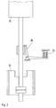
- Fig. 1 the section isolator with the two catenary sections and the bypass switch is shown in the idle state and in Fig. 2 details of the type of locking the switch during the dropout delay.
- the left end section of the catenary is designated 1, the right catenary section with 2.
- the catenary sections 1 and 2 support cable sections 3 and 4 are provided; the catenary section 1 is connected to the support cable 3 via a current connector 5 and the catenary section 2 is connected to the support cable 4 via a current connector 6.
- the catenary section 1 is connected to a pair of grinding skids 7 passing the insulator 29, which overlaps with the catenary end 8 of the catenary section 2 to such an extent that an electrical connection is always ensured when a current collector contact piece passes over it.
- An auxiliary electrode 9 is arranged with its elongated section 9a isolated in the overlap region near the contact wire end 8, section 9a still projecting approximately beyond the two open ends of the pair of grinding runners 7.
- the section 9b of the auxiliary electrode 9 surrounds the insulator fitting 29a in the form of a tube or cage.
- the bypass switch which is provided above the point of separation of the two contact lines, has the switching unit 11 inside an insulator 10, which is preferably designed as a vacuum switch.
- a fixed contact piece 12 and a movable contact piece 13 are provided, which are conductively connected to the insulator fittings 17 and 18 by leads 14 and 15.
- the magnetic drive designed as a plunger core magnet is accommodated in the cylindrical armature 18. Other magnetic shapes can also be used.
- the magnetic drive consists of the fixed magnetic part 19 with the drive coil 20 and the movable plunger 21. In the switch-off position shown, the plunger is pressed against a stop by the switch-off spring 22 pressed. As a result, the movable contact piece 13 is held in the off position against the atmospheric force acting in the closing direction.
- the coil 20 of the drive magnet 19 is supplied with current by the saturation current converter 25.
- the primary winding of this current transformer is connected to the auxiliary electrode 9 and the second contact line section 2 via the lines 26 and 27.
- the arcing current therefore flows through the primary winding.
- the core of the saturation current transformer consists of iron with an almost rectangular magnetization characteristic. This ensures that the voltage time area emitted by the secondary winding via lines 28 and 30 is almost constant regardless of the greatly different primary current of the converter.
- the secondary voltage is rectified in the rectifier 42 and fed via lines 31 and 32 to the coil 20 of the drive magnet.
- An interruption contact 33 which is actuated by the electronic delay switch 34, is arranged in the line 32.
- a voltage-dependent resistor 35 is provided at the output of the rectifier 42 between the lines 31 and 32.
- This voltage-dependent resistor which acts as a voltage limiter, absorbs the current peaks in the secondary winding of the current transformer that occur at high primary currents.
- the solenoid 20 is operated with a certain overvoltage. With this overvoltage, the magnet's pull-in time is considerably less than the specified value of approx. 80 ms. Therefore, the delay element 34 is provided, which closes the contact 33 with an adjustable delay such that the Bypass switch switches with certainty after a predetermined time of, for example, 80 ms.
- a lock 36 is therefore provided, which holds the movable contact piece 13 in the switched-on state, as long as the auxiliary magnet 37 is excited.
- the auxiliary magnet 37 and a capacitor 38 connected in parallel are connected to the rectifier 42 via a diode 39.
- the capacitor is charged as long as the arc current flows and the converter 25 outputs voltage.
- the drive magnet 20 is de-energized very quickly in accordance with its time constant, so that the spring force of the return spring 22 predominates.
- the lock 36 prevents the movable contact piece 13 from resetting. After a delay time predetermined by the capacitance of the capacitor 38 and the auxiliary solenoid coil 37, the switch-on lock is released and the vacuum switch opens at the required contact speed.
- a further electronic delay element 40 is provided according to another embodiment of the invention, which connects the connection between the Capacitor 38 and the auxiliary solenoid 37 interrupts.
- the capacitance of the capacitor 38 must be chosen larger than when the drop-out delay is realized only by means of a capacitor and auxiliary solenoid coil, since the capacitor 38 in the illustrated additional arrangement of the electronic delay element 40 also has to feed this element beyond the drop-out delay and that Fall time is determined only by the electronic delay element.
Landscapes
- Engineering & Computer Science (AREA)
- Mechanical Engineering (AREA)
- Current-Collector Devices For Electrically Propelled Vehicles (AREA)
- Insulators (AREA)
- Non-Insulated Conductors (AREA)
- Suspension Of Electric Lines Or Cables (AREA)
- Transition And Organic Metals Composition Catalysts For Addition Polymerization (AREA)
- Glass Compositions (AREA)
- Driving Mechanisms And Operating Circuits Of Arc-Extinguishing High-Tension Switches (AREA)
Claims (8)
- Isolateur de section pour séparer électriquement une première et une deuxième section d'une caténaire électrique pour des véhicules moteurs, comportant un isolateur (29) qui sépare électriquement les sections, dans lequel il est prévu, aux fins de permettre le passage d'un pantographe, des patins (7) qui sont liés électriquement à la première section (1) et s'étendent jusque dans la deuxième section (2), une électrode auxiliaire (9) qui part de l'isolateur (29), est isolée par rapport aux patins (7) et à la deuxième section de caténaire (2) et s'étend jusque dans la deuxième section de caténaire (2), au-dessus de la zone de recouvrement formée par les patins (7) et ladite deuxième section de caténaire (2), la bobine d'actionnement (20) d'un contacteur (11) est intercalée entre l'électrode auxiliaire (9) et la deuxième section de caténaire (2), la racine d'un arc électrique produit lors du passage du pantographe sur l'isolateur de section est commuté de la deuxième section de caténaire (2) vers l'électrode auxiliaire (9) et le courant d'arc entraîne le déclenchement du contacteur (11) qui éteint l'arc par pontage et, après extinction de l'arc, le contacteur (11) temporisé par un dispositif de temporisation (38,40) revient dans son état précédent, caractérisé par le fait que la bobine d'actionnement (20) du contacteur (11) est connectée indirectement à l'électrode auxiliaire (9) et à la deuxième section de caténaire (2) par l'intermédiaire d'un convertisseur de courant saturé (25), dont la tension secondaire appliquée à la bobine d'actionnement (20) est constante et ne dépend pas de la valeur du courant d'arc qui circule dans l'enroulement primaire.
- Isolateur de section selon la revendication 1, caractérisé par le fait qu'un redresseur (42) destiné à redresser la tension alternative de sortie est connecté à l'enroulement secondaire du convertisseur de courant saturé (25) et par le fait que la bobine d'actionnement (20) du contacteur est agencée sous forme de bobine à courant continu.
- Isolateur de section selon l'une des revendications 1 à 2, caractérisé par le fait qu'une résistance (35) non linéaire est connectée au secondaire du convertisseur de courant saturé (25).
- Isolateur de section l'une des revendications 1 à 3, caractérisé par le fait que la tension secondaire du convertisseur de courant saturé (25) est appliquée à la bobine d'actionnement (20) par l'intermédiaire du contacteur (33) avec un retard qui est déterminé par une horloge électronique (34).
- Isolateur de section selon l'une des revendications 1 à 4, caractérisé par le fait que l'enroulement primaire du convertisseur de courant saturé (25) est connecté à l'électrode auxiliaire (9) et à la deuxième section de caténaire (2), que le commutateur temporisé (34) est connecté à l'enroulement secondaire et que le commutateur temporisé, après écoulement du temps de temporisation, applique la tension secondaire à la bobine d'actionnement (20) (par l'intermédiaire du contact (33)).
- Isolateur de section selon l'une des revendications 1 à 5, caractérisé par le fait que le porte-contact (13) mobile du contacteur comporte un moyen de verrouillage (36) en position fermée qui est maintenu par un aimant auxiliaire (37) pendant un temps de temporisation prédéterminé après extinction de l'arc.
- Isolateur de section selon l'une des revendications 1 à 6, caractérisé par le fait que la durée de temporisation entre l'extinction de l'arc et la retombée de l'aimant auxiliaire (37) est obtenue au moyen d'un condensateur (38) qui est placé en parallèle avec la bobine de l'aimant auxiliaire (37) et, pendant la durée de l'arc électrique, est chargé par l'intermédiaire d'une diode (39) à partir du convertisseur de courant saturé (25).
- Isolateur de section selon l'une des revendications 1 à 7 caractérisé par le fait que pour respecter exactement la temporisation entre l'extinction de l'arc et la retombée de l'aimant auxiliaire, il est prévu un commutateur temporisé (40) électronique qui coupe l'aimant auxiliaire (37) (par l'intermédiaire du contact 41), la capacité du condensateur (38) branché en parallèle avec l'entrée du commutateur électronique (40) étant supérieure à ce qui est nécessaire pour obtenir là temporisation lorsque le condensateur et la bobine de l'aimant auxiliaire sont branchés en parallèle.
Applications Claiming Priority (2)
| Application Number | Priority Date | Filing Date | Title |
|---|---|---|---|
| DE3816841A DE3816841A1 (de) | 1988-05-18 | 1988-05-18 | Streckentrenner in fahrleitungen |
| DE3816841 | 1988-05-18 |
Publications (3)
| Publication Number | Publication Date |
|---|---|
| EP0342540A2 EP0342540A2 (fr) | 1989-11-23 |
| EP0342540A3 EP0342540A3 (fr) | 1991-04-17 |
| EP0342540B1 true EP0342540B1 (fr) | 1994-07-27 |
Family
ID=6354582
Family Applications (1)
| Application Number | Title | Priority Date | Filing Date |
|---|---|---|---|
| EP89108582A Expired - Lifetime EP0342540B1 (fr) | 1988-05-18 | 1989-05-12 | Isolateur de sections dans des lignes de traction |
Country Status (4)
| Country | Link |
|---|---|
| EP (1) | EP0342540B1 (fr) |
| AT (1) | ATE109081T1 (fr) |
| DE (2) | DE3816841A1 (fr) |
| NO (1) | NO175417C (fr) |
Families Citing this family (2)
| Publication number | Priority date | Publication date | Assignee | Title |
|---|---|---|---|---|
| US5117072A (en) * | 1990-09-13 | 1992-05-26 | White Paul F | Constant current non-bridging section insulator |
| KR101155557B1 (ko) | 2010-11-19 | 2012-06-19 | 한국철도기술연구원 | 내마모성이 개선된 절연재를 채용한 절연구분장치 |
Family Cites Families (2)
| Publication number | Priority date | Publication date | Assignee | Title |
|---|---|---|---|---|
| DE2548986C2 (de) * | 1975-11-03 | 1982-07-01 | Brown, Boveri & Cie Ag, 6800 Mannheim | Streckentrenner |
| DE3321465A1 (de) * | 1983-06-14 | 1984-12-20 | Siemens AG, 1000 Berlin und 8000 München | Anordnung zum unterdruecken eines lichtbogens an einem streckentrenner |
-
1988
- 1988-05-18 DE DE3816841A patent/DE3816841A1/de not_active Withdrawn
-
1989
- 1989-05-12 AT AT89108582T patent/ATE109081T1/de not_active IP Right Cessation
- 1989-05-12 DE DE58908094T patent/DE58908094D1/de not_active Expired - Fee Related
- 1989-05-12 EP EP89108582A patent/EP0342540B1/fr not_active Expired - Lifetime
- 1989-05-16 NO NO891959A patent/NO175417C/no unknown
Also Published As
| Publication number | Publication date |
|---|---|
| DE58908094D1 (de) | 1994-09-01 |
| EP0342540A2 (fr) | 1989-11-23 |
| NO175417C (no) | 1994-10-12 |
| DE3816841A1 (de) | 1989-11-23 |
| NO891959D0 (no) | 1989-05-16 |
| EP0342540A3 (fr) | 1991-04-17 |
| NO891959L (no) | 1989-11-20 |
| NO175417B (no) | 1994-07-04 |
| ATE109081T1 (de) | 1994-08-15 |
Similar Documents
| Publication | Publication Date | Title |
|---|---|---|
| EP3084960B1 (fr) | Dispositif de commutation pour le passage et la coupure de courants électriques | |
| DE260903C (fr) | ||
| EP1260823A1 (fr) | Circuit d'essais synthétiques du pouvoir de coupure pour disjoncteurs à courant alternatif à haute tension | |
| EP3440686B1 (fr) | Dispositif de commutation pour acheminer et couper des courants électriques | |
| EP0793318A1 (fr) | Dispositif dérivateur de surtensions | |
| DE4018674C2 (de) | Kontaktanordnung für ein elektrisches Schaltgerät, insbesondere für ein Schütz | |
| DE4110335C2 (de) | Einrichtung zum Kurzschlußschutz | |
| EP2309526B1 (fr) | Commutateur de puissance avec des branches de courant nominal parallèles | |
| EP0342540B1 (fr) | Isolateur de sections dans des lignes de traction | |
| DE2508299A1 (de) | Elektrisches schaltgeraet | |
| EP0136965A1 (fr) | Sectionneur pour appareillage de commutation haute tension logé dans une enceinte métallique à gaz comprimé | |
| EP2122647B1 (fr) | Réseau électrique à courant continu pour navires et installations en mer présentant une sécurité de coupure accrue | |
| EP0556652A2 (fr) | Dispositif de protection électromécanique | |
| DE2548986C2 (de) | Streckentrenner | |
| DE1913548A1 (de) | Gleichstrom-Hochspannungsunterbrecher | |
| DE4205501C1 (en) | High tension switch preventing arcing when switched off - has two slidable contacts surrounded by insulating nozzle during on state, and control electrode surrounding nozzle. | |
| DE10005825C2 (de) | Elektrischer Niederspannungsschalter | |
| DE1017248B (de) | Wechselstromschalteinrichtung | |
| DE1790078A1 (de) | Magnetische Bogen-Loeschvorrichtung | |
| DE2542724A1 (de) | Ueberstromschalter | |
| DE4337810A1 (de) | Prüfkreis für die synthetische Prüfung von Hochspannungsleistungsschaltern | |
| DE2331859A1 (de) | Streckentrenner | |
| EP1064663A1 (fr) | Bobine de soufflage pour sectionneurs sous charge isoles des gaz | |
| DE10064525A1 (de) | Mittelspannungsschalteinrichtung | |
| DE1515603A1 (de) | Schalteranordnung zum Ein- und Ausschalten eines wechselstromgespeisten Verbrauchers |
Legal Events
| Date | Code | Title | Description |
|---|---|---|---|
| PUAI | Public reference made under article 153(3) epc to a published international application that has entered the european phase |
Free format text: ORIGINAL CODE: 0009012 |
|
| AK | Designated contracting states |
Kind code of ref document: A2 Designated state(s): AT CH DE GB IT LI SE |
|
| PUAL | Search report despatched |
Free format text: ORIGINAL CODE: 0009013 |
|
| AK | Designated contracting states |
Kind code of ref document: A3 Designated state(s): AT CH DE GB IT LI SE |
|
| 17P | Request for examination filed |
Effective date: 19910523 |
|
| 17Q | First examination report despatched |
Effective date: 19940113 |
|
| GRAA | (expected) grant |
Free format text: ORIGINAL CODE: 0009210 |
|
| AK | Designated contracting states |
Kind code of ref document: B1 Designated state(s): AT CH DE GB IT LI SE |
|
| REF | Corresponds to: |
Ref document number: 109081 Country of ref document: AT Date of ref document: 19940815 Kind code of ref document: T |
|
| REF | Corresponds to: |
Ref document number: 58908094 Country of ref document: DE Date of ref document: 19940901 |
|
| GBT | Gb: translation of ep patent filed (gb section 77(6)(a)/1977) |
Effective date: 19940815 |
|
| ITF | It: translation for a ep patent filed |
Owner name: DE DOMINICIS & MAYER S.R.L. |
|
| EAL | Se: european patent in force in sweden |
Ref document number: 89108582.1 |
|
| PLBE | No opposition filed within time limit |
Free format text: ORIGINAL CODE: 0009261 |
|
| STAA | Information on the status of an ep patent application or granted ep patent |
Free format text: STATUS: NO OPPOSITION FILED WITHIN TIME LIMIT |
|
| 26N | No opposition filed | ||
| PGFP | Annual fee paid to national office [announced via postgrant information from national office to epo] |
Ref country code: GB Payment date: 19970421 Year of fee payment: 9 Ref country code: AT Payment date: 19970421 Year of fee payment: 9 |
|
| PGFP | Annual fee paid to national office [announced via postgrant information from national office to epo] |
Ref country code: CH Payment date: 19970512 Year of fee payment: 9 |
|
| PGFP | Annual fee paid to national office [announced via postgrant information from national office to epo] |
Ref country code: DE Payment date: 19970513 Year of fee payment: 9 |
|
| PGFP | Annual fee paid to national office [announced via postgrant information from national office to epo] |
Ref country code: SE Payment date: 19970514 Year of fee payment: 9 |
|
| PG25 | Lapsed in a contracting state [announced via postgrant information from national office to epo] |
Ref country code: GB Free format text: LAPSE BECAUSE OF NON-PAYMENT OF DUE FEES Effective date: 19980512 Ref country code: AT Free format text: LAPSE BECAUSE OF NON-PAYMENT OF DUE FEES Effective date: 19980512 |
|
| PG25 | Lapsed in a contracting state [announced via postgrant information from national office to epo] |
Ref country code: SE Free format text: LAPSE BECAUSE OF NON-PAYMENT OF DUE FEES Effective date: 19980513 |
|
| PG25 | Lapsed in a contracting state [announced via postgrant information from national office to epo] |
Ref country code: LI Free format text: LAPSE BECAUSE OF NON-PAYMENT OF DUE FEES Effective date: 19980531 Ref country code: CH Free format text: LAPSE BECAUSE OF NON-PAYMENT OF DUE FEES Effective date: 19980531 |
|
| GBPC | Gb: european patent ceased through non-payment of renewal fee |
Effective date: 19980512 |
|
| REG | Reference to a national code |
Ref country code: CH Ref legal event code: PL |
|
| EUG | Se: european patent has lapsed |
Ref document number: 89108582.1 |
|
| PG25 | Lapsed in a contracting state [announced via postgrant information from national office to epo] |
Ref country code: DE Free format text: LAPSE BECAUSE OF NON-PAYMENT OF DUE FEES Effective date: 19990302 |
|
| PG25 | Lapsed in a contracting state [announced via postgrant information from national office to epo] |
Ref country code: IT Free format text: LAPSE BECAUSE OF NON-PAYMENT OF DUE FEES;WARNING: LAPSES OF ITALIAN PATENTS WITH EFFECTIVE DATE BEFORE 2007 MAY HAVE OCCURRED AT ANY TIME BEFORE 2007. THE CORRECT EFFECTIVE DATE MAY BE DIFFERENT FROM THE ONE RECORDED. Effective date: 20050512 |