EP0342528A2 - Méthode de rectification de cames d'arbre à cames - Google Patents
Méthode de rectification de cames d'arbre à cames Download PDFInfo
- Publication number
- EP0342528A2 EP0342528A2 EP89108527A EP89108527A EP0342528A2 EP 0342528 A2 EP0342528 A2 EP 0342528A2 EP 89108527 A EP89108527 A EP 89108527A EP 89108527 A EP89108527 A EP 89108527A EP 0342528 A2 EP0342528 A2 EP 0342528A2
- Authority
- EP
- European Patent Office
- Prior art keywords
- grinding
- maximum
- grinding wheel
- cams
- camshaft
- Prior art date
- Legal status (The legal status is an assumption and is not a legal conclusion. Google has not performed a legal analysis and makes no representation as to the accuracy of the status listed.)
- Withdrawn
Links
Images


Classifications
-
- G—PHYSICS
- G05—CONTROLLING; REGULATING
- G05B—CONTROL OR REGULATING SYSTEMS IN GENERAL; FUNCTIONAL ELEMENTS OF SUCH SYSTEMS; MONITORING OR TESTING ARRANGEMENTS FOR SUCH SYSTEMS OR ELEMENTS
- G05B19/00—Program-control systems
- G05B19/02—Program-control systems electric
- G05B19/18—Numerical control [NC], i.e. automatically operating machines, in particular machine tools, e.g. in a manufacturing environment, so as to execute positioning, movement or co-ordinated operations by means of program data in numerical form
- G05B19/182—Numerical control [NC], i.e. automatically operating machines, in particular machine tools, e.g. in a manufacturing environment, so as to execute positioning, movement or co-ordinated operations by means of program data in numerical form characterised by the machine tool function, e.g. thread cutting, cam making, tool direction control
- G05B19/184—Generation of cam-like surfaces
Definitions
- the invention relates to a method for grinding cams of a camshaft by means of a numerically controlled camshaft grinding machine, in which the camshaft is arranged in a workpiece holder with a predetermined angular velocity in predetermined angular increments around its longitudinal axis and a grinding slide with a grinding wheel in an axis perpendicular to the longitudinal axis can be set in predetermined steps, depending on the geometry, the material and the desired surface quality of the camshaft and the cams, a grinding wheel is selected in its nature for processing and the infeed of the grinding wheel is adjusted.
- the invention is based on the object of developing a method of the type mentioned at the outset such that the physical mechanisms of the cam shape grinding are brought into a closed operating cycle with tool specifications and process parameters, in order to ensure, from an economic point of view, i.e. to find an optimum with minimal grinding time, making maximum use of what is physically possible.
- this object is achieved by the following method steps: - Determining a minimum grinding time from the geometry of the cams and the maximum angular velocity; - Determining a maximum related chip removal volume as a function of the maximum drive power of the grinding wheel drive; - Determination of a maximum machined workpiece volume from the minimum grinding time and the maximum related chip removal volume; - Determining a maximum infeed from the maximum machined workpiece volume and the geometry of the cams; - Determining a grinding wheel type from a table of predetermined grinding wheel types depending on the predetermined roughness depth of the cam; - Grinding the cams by means of the specific grinding wheel while setting the maximum infeed.
- the object underlying the invention is completely achieved in this way.
- the two most critical parameters of the grinding process are assumed, namely the maximum possible angular velocity of the so-called C-axis on the one hand and the drive power of the grinding wheel on the other, in order to use the special geometry of the camshaft cams to be machined to obtain a maximum related chip removal volume as a critical parameter of the to determine the inventive method.
- This maximum related chip removal volume then in turn determines the maximum infeed via the geometry of the cams in such a way that when this infeed is set the grinding machine is operated at the limit of its possible performance data.
- an associated grinding wheel can then be determined in order to then allow the cam shape grinding process to take place.
- the following steps are additionally used: - Determining the degree of chip filling from the maximum drawn chip removal volume; - Comparing the determined degree of chip filling with a limit value; - Reduction of the maximum amount of chip removal used until the chip filling degree does not exceed the limit value; - Determining the associated maximum infeed from the reduced maximum time span volume obtained; - Grinding the cams using the specific grinding wheel while setting the maximum infeed.
- the following further steps are used: - Determination of the individual grain force from the maximum obtained chip removal volume; - Comparing the determined single grain force with a second limit value; - reducing the maximum amount of chip removal obtained until the individual grain force does not exceed the second limit value; - Determining the associated maximum infeed from the reduced maximum time span volume obtained; - Grinding the cams using the specific grinding wheel while setting the maximum infeed.
- This measure has the advantage that the resilience of the grains of the grinding wheel is tightened as a further process parameter, in order to prevent premature excessive wear of the grinding wheel if the grinding power is too high. In this case too, a certain reduction in the grinding performance is accepted in the interest of fulfilling this secondary condition.
- a maximum related chip removal volume is determined from a further boundary condition, in each case Larger chip removal volume used to determine the maximum infeed for grinding the cams.
- This measure has the advantage that in addition to the boundary conditions already mentioned, further boundary conditions that result from empirically determined dependencies are taken into account in turn via the central process variable, namely the maximum amount of material removal. In this case too, a certain reduction in grinding performance, i.e. an increase in processing time is accepted in order to be able to meet additional boundary conditions depending on their expediency.
- these additional boundary conditions can be the roughness depth of the cams and grinding wheel or the shape error of the cams or the cutting performance of the camshaft grinding machine or the wear of the grinding wheel or the peripheral zone temperature of the cams or the machined workpiece volume.
- the method according to the invention is particularly suitable for the user-controlled operation of a cam form grinding machine via a screen menu control with a graphic dialog, in which the user of the grinding machine is given screen masks one after the other in which he can insert the still missing characteristic values of the respective processing task.
- the numerical control of the grinding machine selects the respective optimal grinding wheel from a stored catalog of actually available grinding wheels from the fixedly specified and a variably entered parameters and automatically sets the required process parameters of the cam-shaped grinding machine, in particular the movement of the C-axis, i.e. the axis of rotation of the camshaft and the X-axis, i.e. the travel of the grinding carriage.
- the aim of the method according to the invention is to implement the machining task, taking into account the material, the raw and finished part geometry and the surface quality, in a machining concept in which a prediction of the tool specification, the conditioning parameters, the technology parameters, the process sequence and the machining time can be made without to carry out experimental trials.
- the information determined for shape grinding of the camshaft is presented to the control of a cam shape grinding machine in a form which enables editing of the proposed numerical control program in accordance with DIN 66025.
- the method according to the invention preferably relates to the field of CBN grinding, in which grinding wheels with an abrasive material made of CBN (cubic boron nitride) crystals are used.
- CBN cubic boron nitride
- the machining task is first defined.
- the workpiece with material, oversize and geometry is specified as the input variable.
- the criteria with vibrations and temperature are specified as the disturbance variable and finally the limit criteria, i.e. the shape defect and the surface quality are defined.
- the technology follows from the machining task, both with regard to the machining kinematics and the machining kinetics.
- the former means the process variables of the infeed, the machining volume, the angular velocity, the cutting speed, the contact length and the equivalent grinding wheel diameter as manipulated variables, while the second one includes the chip removal volume, the cutting force, the power, the process duration, the wear and the dynamic stiffness understood as process variables.
- the tool is then determined from the machining task and the technology based on the design and conditioning.
- the former means the state variables of the specification and the topography, while the second is the core variables, i.e. understands the infeed and the dressing speed strategy.
- the technology and the tool then ultimately result in the machining concept, for which the result variables, namely the cutting value optimization for minimum grinding time and the control variables for the NC program according to the raw / finished part description, production data, machining sequence, conditioning strategy and execution instructions, are output as a protocol.
- the result variables namely the cutting value optimization for minimum grinding time and the control variables for the NC program according to the raw / finished part description, production data, machining sequence, conditioning strategy and execution instructions
- the workpiece characteristics (material, oversize and geometry) are initially specified as input variables and the limit criteria (shape error of the cam contour, surface quality, thermal boundary zone influence) as output variables in order to determine the machining strategy therefrom.
- the limit criteria shape error of the cam contour, surface quality, thermal boundary zone influence
- a machining concept is defined so that a minimal grinding time with optimal cutting values is made possible, which determine the NC program as the control variable as the result variables.
- An essential part of the proposed method is the specification of the physical mechanism of action of the machining process with an analytical consideration of the cutting edge movement during grinding as well as the interaction of the individual components at the cutting point.
- the method according to the invention is preferably represented as a graphic dialog on the cam shape grinding machine in a manner which is easy to handle for the user of the grinding machine.
- a group of materials can be specified in an advantageous manner, because experience has shown that the camshafts to be ground only consist of a finite number of materials.
- the user of the grinding machine therefore only needs to specify a certain standardized material by means of a code number.
- the geometry parameters of the cam contour are kinetodynamically analyzed by means of multiple derivation over time and represented as process parameters, as is known per se.
- the tool paths in the X-axis and the perpendicular Z-axis are also shown graphically and can be specified by the user of the grinding machine depending on the application.
- the specified roughness depth of the cam contour to be machined defines the grain size and thus the concentration of the CBN grinding wheel.
- the theoretical grain protrusion is first derived and then the chip space volume is determined by means of the grain distance. It is assumed that the CBN grit is integrated in the grinding wheel bond by means of cylindrical tie bars, which give the grit a stiffness depending on the modulus of elasticity (2-10 x 104 N / mm2), the bending strength (25-150 N / mm2 ) and the compressive strength (100-1000 N / mm2) anchored in the binding. It is important here that ceramic bonds of CBN grains are preferably considered in the context of the present method.
- the conditioning parameters are determined according to the theoretical grain wear and the theoretical removal ratio.
- the parameters of a multi-stage grinding process which determine the machine setting for cam shape grinding in the plunge-in process as a control variable, are the cutting speed v C , the workpiece angular speed ⁇ W and the infeed per revolution a.
- the cutting speed v c can be regarded as a constant parameter which is determined in a multi-stage process in accordance with the respective grinding task.
- the cutting speed corresponds in a first approximation to the peripheral speed of the grinding wheel.
- v w 2 ⁇ r i ⁇ n / 60,000 (m / s) [2]
- With n ⁇ w / 360 (min ⁇ 1) [3] is.
- the length of the engagement arc results from the curvatures of the grinding wheel and workpiece as well as from the Radial feed.
- the radial feed corresponds to the infeed amount of the grinding wheel per workpiece revolution.
- the cutting volume is given by the cam geometry and the infeed per workpiece revolution: Where b is the cam width, ⁇ G the base circle angle, R G the base circle radius, R G the base circle radius, ⁇ F the flank angle, R K the flank radius for an interval, ⁇ S the tip angle and R S the tip radius.
- the chip removal volume can be calculated from the cutting volume and the grinding time per cam revolution:
- the cutting performance can be calculated from the chip removal volume Q w '.
- k means a constant and n an exponential coefficient, which takes into account the respective workpiece-related relationship between chip formation and friction energy.
- the specific cutting energy can be represented in a similar manner depending on the volume of chip removal.
- the cutting force at a constant chip removal rate is given by the equation given. With constant cutting performance and increasing cutting speed, the cutting force decreases degressively. This connection is ultimately due to the reduction in the chip cross-section.
- the cutting force is determined as the sum of the individual forces currently acting on the cutting edges in the cutting.
- the individual force components of a collective of cutting a grinding wheel during external plunge grinding are the cutting tangential force F ct and the cutting normal force F c ⁇ .
- the normal cutting force F cn can be found in the relationship determine, where the proportionality factor ⁇ represents the cutting force ratio
- the cutting force ratio mainly corresponds to the shape of the cutting edge, the kinematic number of cutting edges, the chip cross section, the grain material, the workpiece material and the coolant conditions.
- the roughness In order to interpret the specification, the roughness must first be taken into account, which is generally prescribed for the respective grinding task. However, the roughness depends on the specification of the CBN grinding tool and on the other hand on the engagement conditions.
- the specification of the CBN grinding tool is selected according to the grain size and concentration in accordance with the process, so that the roughness requirement can be met under the kinematic and kinetic conditions still to be explained.
- the specification of the grinding tool determines the initial effective roughness, with small grain sizes and increasing concentration the initial effective roughness decreases. A large grain and decreasing concentration increases the initial effective roughness.
- the grain size and the concentration of a CBN grinding wheel result in the surface quality of the grinding tool, so that there is sufficient space between the peripheral CBN grains for the chips to be produced.
- the type and hardness of the bond exerts an influence on the grinding wheel topography and on the breaking out of the CBN grains from the formation (ceramic). If the bond is harder, the CBN crystals remain in the bond longer, so that the edges in the grinding process are primarily blunted. This not only changes the grain shape, but also the number of cutting edges.
- the type of bond in a grinding wheel specification is dependent on the grain density C K , which is selected as the grain size to describe the number of grains per mm3 volume of grinding wheel.
- C K grain density
- the area-related kinematic number of cutting edges, the cutting volume per cutting edge, the cutting space volume and the cutting space filling degree must be taken into account. This creates the possibility, using analytical parameters, to carry out a theoretical coordination between the volumes of the machining process on the one hand by means of the technology parameters and the tool on the other hand via the topography with a defined specification.
- the workpiece wear is examined, which is caused not only by changed grain geometry, but also by the breaking out of the grains with high grain load and unadjusted strength of the binding material.
- the following relationship can be described for the area-related kinematic number of cutting edges: where K is the volume-related concentration, W m is the mean mesh size for the grains, ie 1.42 times the grain diameter d k for an octahedron and finally q is the speed ratio, as already shown above.
- the area-related kinematic number of cutting edges has the dimension mm ⁇ 2.
- the individual chip volume can be determined by the equation depending on the cutting conditions and the grinding wheel specification determine.
- the theoretical mean grain protrusion and the grain spacing should first be determined.
- the grain spacing can then be determined by the equation to calculate.
- chip space filling degree The relationship between the individual chip volume and the associated chip space volume is defined as the so-called chip space filling degree
- the degree of chip filling depends largely on the material to be machined, if one assumes that the specification and the topography are adapted to the requirements of the cutting conditions. Depending on the material and material condition, the chips have different shapes. In the real grinding process, the chips require a larger chip space volume than their own volume. From this it can be deduced that the chip filling degree must not exceed a certain limit value, for example 0.75, if an overloading of the abrasive coating is to be avoided.
- the stability of the grinding tool is very important when plunge grinding. If the radial wear exceeds a certain permissible level, the required shape can only be created again by conditioning (dressing).
- the conditioning interval is often used to assess the grinding process. It is specified as the ratio of the removed material volume to the radial grinding wheel wear by the so-called grinding ratio or referred to as the removal ratio G.
- the load on the individual grain is determined by the number of cutting edges over which the cutting force is distributed as a result of the grinding wheel specification and the process parameters.
- the effective cutting edge spacing l K and the engagement length are dependent on the infeed and the cutting speed in addition to other influencing variables.
- the effect of the change in the kinematic quantities v s and V w on the chip thickness a n is determined by the relationship shown.
- the chip thickness decreases. Due to the fact that fewer cutting edges are engaged, the total cutting force is reduced.
- the contact zone temperatures can be reduced by reducing the contact time between the abrasive grain and the workpiece while the grain has a high thermal conductivity.
- the thermal conductivity of CBN grain is 700 W / m ° C and is significantly higher than that of conventional aluminum oxide.
- the conditioning of the grinding wheel must be taken into account as a further process parameter.
- grinding wheels lose both their original starting profile and their cutting ability as a result of wear. There is a change in the grinding wheel topography as a function of the grinding time.
- the task of conditioning is to bring the topography of the grinding surface back to its original shape.
- Diamond form rollers or sharpening rods are used as conditioning tools.
- the conditioning parameters with regard to the rotating diamond tool are the shape sizes: profile shape, specification (grain density, settlement pattern) and the setting sizes: infeed per conditioning process, circumferential speed of the roll, axial side feed and speed quotient.
- V d a pd / f ad [32] as the quotient of the effective width of the roller profile and side feed of the roller per grinding wheel revolution, these values for V d lie between 1 and 6, so that the theoretical axial ripple is minimal.
- the speed quotient results from the peripheral speed of the diamond roller v R and the grinding wheel v S. Changing directions of rotation of the roller (co-rotation and counter-rotation), the speed quotient and the axial side feed influence the initial effective roughness.
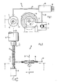
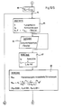
- a camshaft 12 is clamped in a workpiece holder 11.
- the camshaft 12 can be rotated about its longitudinal axis 13, the so-called C axis, in defined angular steps by means of the rotating workpiece holder 11, as indicated by an arrow 14.
- the angular velocity of the workpiece holder 11 is identified by ⁇ .
- a grinding carriage 17 carries a grinding wheel 18 which can be driven by means of a drive motor 19.
- the power of the drive motor 19 is denoted by P.
- the grinding carriage 17 with grinding wheel 18 can be advanced along an axis 20, the so-called X axis perpendicular to the C axis 13 of the camshaft 12, in defined X steps.
- the grinding wheel 18 can be moved toward the camshaft 12 for machining the surface of the camshaft 12 in this way.
- the grinding wheel 18 rotates about its axis 21, which coincides with the so-called Z axis.
- the grinding slide 17 or the workpiece holder 11 can namely be additionally displaced in the direction of the Z-axis 21 so that the grinding wheel 18 can process the individual cams of the camshaft 12 one after the other.
- an NC control device 25 is provided, to which input parameters 26 can be supplied. From this, the NC control unit 25 derives control signals which are fed to the drive of the workpiece holder 11 and the drive of the grinding carriage 17 via data lines 27 and 28. A distinction is made here between the so-called “delivery operation” and the so-called “rail operation”. In the infeed mode, the grinding wheel 18 is advanced along the X axis 20 to the camshaft 12 in order to achieve a certain material removal during grinding.
- the grinding wheel 18 is moved along the X axis 20 as a function of the respective rotational position of the camshaft 12 adjusted about the C-axis 13 so that the point of engagement or the line of engagement on the grinding surface of the grinding wheel 18 always abuts a desired point on the cam contour of the camshaft 12.
- the cams of the camshaft 12 can be ground along a spiral grinding path which begins on the raw surface of the unprocessed cam and ends on the contour of the finished surface of the cam.
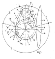
- Fig. 3 shows a cam 30 of the camshaft 12 with further details.
- the cam 30 has a so-called base circle 31, a tip 32 and lateral flanks 33.
- first point 34 the grinding wheel 18 engages with a surface line on the surface of the cam 30.
- second points 35 the base circle 31 merges into the flanks 33.
- the second points 35 thus define the so-called base circle angle ⁇ G.
- the radius of the base circle is designated R G.
- Third points 36 mark the transition from the flanks 33 to the tip 32. They thus define the so-called flank angle ⁇ F and the tip angle ⁇ S.
- the radius of the tip is labeled R S.
- a fourth point 37 denotes an arbitrary point, for example on the tip 32, to which a tangent 38 to the Cam contour is laid. If a parallel tangent to the base circle 31 is drawn to the tangent 38, the distance between the parallel tangents 38, 39 gives the so-called survey value E.
- a fifth point 40 and a sixth point 41 denote any points on the contour of the cam 30, shown using the example of two points on the flank 33.
- the radii of curvature of points 40, 41 are denoted by R Fi and by R Fn . This is to say that the radius of curvature varies with R Fi or R Fn in the area of the flanks 33, ie over the flank angle ⁇ F , while the radius of curvature with R G in the area of the base circle 31 over the base circle angle ⁇ G is as constant as with R S over the tip 32 or the tip angle ⁇ S.
- the contour of the cam 30 can thus be represented, for example, as a table of polar coordinates, but there are also forms of representation in which a so-called survey value table is specified, which represents the survey value E over an angle ⁇ .
- the table given is converted into control commands for the angle of rotation of the C-axis 13 and the drive unit for the X-axis 20 of the grinding carriage 17 in order to determine the rail operation, taking into account the grinding wheel diameter.
- FIG. 3 shows in a section 42 with a greatly enlarged representation the roughness depth R Z which is to be generated on the surface of the cam 30 by grinding.
- the material used is symbolized in section 42 with W.
- the material symbolized with W is not a continuously variable size. Rather, a limited number of materials can be specified for the practical applications of the method according to the invention, as are usually used as camshaft materials. These include, in particular, chilled cast iron, malleable cast iron, pearlitic cast iron and it must also be taken into account whether these materials are case hardened or inductively hardened. In practice, this finite number of possibilities can be symbolized by a finite number of code numbers which can be selected by the user of the method according to the invention.
- Fig. 4 shows a camshaft 12 as it can be processed with the inventive method.
- the camshaft 12 has n cams 30/1, 30/2 ... 30 / n.
- camshafts 12 with a total of 8 cams can be ground using the method according to the invention.
- the grinding wheel 18 is set in the Z-axis so that it faces the first cam 30/1.
- the distance of the grinding wheel 18 from the first Cam 30/1 in the X axis 20 is an initial value X A. This value must be specified for the method according to the invention so that the cam shape grinding machine can travel through this initial feed path at the beginning of the method before the grinding wheel 18 comes into contact with the first cam 30/1.
- the cam width b must also be entered to determine the process parameters.
- a CBN grain 50 ie a crystal of cubic boron nitride, is shown in FIG. 5, which ideally has the shape of an octahedron.
- the diameter of the CBN grain 50 is denoted by d K and its volume by V K.
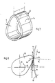
- FIG. 6 shows, several of these grains 50, namely grains 50/1, 50/2 ... 50 / n, are integrated in a ceramic bond 55 in a real grinding wheel 18.
- the concentration of the grains 50 is denoted by K.
- the distance between two grains 50/1 and 50/2 is 1 K and the theoretical grain overhang is a static mean Z t .
- the chip space volume V SR between two grains 50/1, 50/2 can be determined from this.
- FIG. 7 shows, in a perspective illustration, a machined volume 60 as is machined on a cam when an infeed a is set at a cam width b.
- the volume V w results as the product of infeed a, width b and circumference of the cam, as will be explained below with reference to FIG. 9.
- Fig. 8 shows the relationships at the effective speeds during the cam shape grinding.
- the cam 30 and the grinding wheel 18 rotate in opposite directions.
- the workpiece speed v w and the grinding wheel speed v S are effective.
- the directions of the speed vectors v W and v S result from the respective radii R S of the grinding wheel 18 and R n of the cam 30, as has already been explained above for FIG. 3 for the cam 30.
- the cutting speed v C results from the geometric addition of the vectors v W and v S and can be calculated according to the amount with the aid of the cosine theorem.
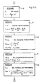
- Fig. 9 finally shows a diagram in which the grinding time t h is plotted for a cam over the related chip removal volume Q ' W.
- the grinding time t h is equal to the quotient of the machined workpiece volume V w (see FIG. 7) and the related chip removal volume Q w '.
- the circumference of the cam 30 is calculated as the sum of the products of circumferential angles ⁇ and radii R, as in FIG. 9 with the relationship is specified. Since the cam width b is constant, the machined volume V w therefore only depends on the variable oversize a.
- the relationship between grinding time t h and related chip removal volume Q w ' is thus expressed in a hyperbolic curve, which is parameterized according to a, as shown in Fig. 9 for two examples a1 and a2.
- a first boundary condition is the achievable surface roughness r t of the workpiece and r to of the grinding wheel 18. With these two sizes and the concentration K of the grinding wheel 18 and the cutting speed v S can be a first relationship for a limit value of the related chip removal volume Q w 'as follows
- the second boundary condition is the shape error f m of the cam, which is known to be the quotient of cutting force F C and system rigidity C g . Then, taking the cam width b into account, the following relationship results:
- the tool wear r s can be specified as a function of the chip filling degree f g , the grain coverage factor ⁇ b s and the theoretical grain protrusion Z r as follows: where Z is an auxiliary variable and the relationship obey.
- the temperature T M can be specified as the fourth boundary condition, and the relationship is:
- the limiting boundary condition in each case is the one with the lowest related chip removal volume Q w ′, in order to then determine the infeed a as a minimum but optimal value, which is then at the minimum grinding time t h min leads.
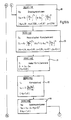
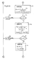
- a determination program is started by first entering the input data either individually in block 71 or retrieving it from machine-specific files.
- the maximum power P max of the drive motor 19 of the grinding wheel 18 of, for example, 22 kW is called up as grinding machine data.
- the maximum angular speeds of the workpiece holder 11 of the C-axis 13 are called, which can be between 10,000 and 30,000 ° / min.
- the rigidity C g of the machine has to be taken into account.
- Material W is first called up as cam data using the table of typical camshaft materials already mentioned. Furthermore, the overall oversize A and the number of cams n of the camshaft 12 are specified. With regard to the cam contour, the base circle radius R G and the contour itself must be specified, for example in the form of the already mentioned data collection table E ( ⁇ ) .
- the cam width b is to be entered, as is the adjustment path X A of the grinding wheel 18 in the direction of the X axis 20 and the starting position Z A of the grinding wheel 18 in the direction of the Z axis 21, as well as the end position Z E in this axis 21 and the cam jump Z S .
- the roughness depth R Z and the shape error f m are specified as cam specifications.
- ⁇ RZ the user can make a yes / no decision with Y / N, with the effect that the further determination of the parameters is carried out either with or without taking the thermal edge zone phenomenon into account.
- the grinding wheel data are also specified in tabular form, for a finite number of CBN grinding wheels available in practice.
- the grinding wheel diameter d S as well as the grain size B and the concentration K can be specified in the known manner.
- a polyhedron constant q m which is 1.4 in the case of an octahedron, is also given, as is the theoretical polyhedron nerve volume W m , which can also be tabulated according to the type of polyhedron, provided that different polyhedra are provided for different grinding wheel coverings.
- the grain coverage factor ⁇ b s , the permissible maximum grain force F Kzul for the grinding wheel and, as conditioning parameters, the dressing infeed a d and the speeds of the dressing roller V fd , V fd ′ are to be specified in the opposite direction.
- the grinding wheel peripheral speed v S , the number of workpieces to be machined per hour N w and finally the conditioning interval of the grinding wheel T s are to be specified as constant processing parameters.
- the cam geometry is first calculated in block 72 according to further characteristic values.
- the workpiece diameter d W , the flank radius R F in the form of a table, the tip radius R S , the maximum elevation value E max and the base circle angle ⁇ G , the flank angle ⁇ F and the tip angle ⁇ S are determined.
- the cutting speed v C of the grinding wheel 18 is determined by means of the vectorial addition from the circumferential cam speed v W and the grinding wheel speed v S.
- the values R G , R F , R S , E max , ⁇ G , ⁇ F , ⁇ S , b, X A , Z A , Z E and Z S are output in the menu already mentioned at the beginning -Technology in the form of a graphic dialog with the user of the method according to the invention.
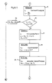
- the camshaft can be represented in two side views in a mask, the values listed in block 75 being illustrated graphically.
- the ratio of cutting speed v C and workpiece speed v W is calculated as a quotient q in block 76.
- an effective diameter d eq is determined as an auxiliary variable from the diameters of workpiece d W and grinding wheel d S.
- the cutting force f C is determined on the basis of an empirical formula from the maximum power P max of the drive motor 19.
- the maximum amount of material removal Q ′ wmax obtained is determined in block 80 as the central variable of the method according to the invention, using an empirically obtained formula from the maximum power P max of the drive motor 19 of the grinding wheel 18.
- the maximum machined workpiece volume V ′ Wmax can be determined from the two values of blocks 79 and 80 thus obtained.
- a maximum infeed a max of the grinding wheel 18 is now determined in block 82 as an output variable for the method according to the invention.
- the maximum reference time span volume Q ′ wi is again specified as the maximum value Q ′ wmax in a block 83 as the central calculation variable.
- this maximum output value Q ′ wmax can still be decremented in the following process by various loop passes, as will be explained in more detail below.
- a specific type of grinding wheel is selected in block 85 from the predetermined roughness depth R Z for the finished cam surface by means of the grinding wheel table, with which said roughness depth R Z can be achieved.
- the grain size is B and the concentration K and thus also the grain diameter d K fixed.
- the determined type of grinding wheel is output in block 86 and in turn is shown in the graphics dialog of the menu control.
- the grain density C K is calculated using equation (17).
- the area-related kinematic cutting edge number N kin is determined using equation (18).
- the chip filling degree f g can finally be determined in block 94.
- decision block 95 it is now checked whether the chip filling degree f g is less than or equal to a predetermined limit value of, for example, 0.75. If this is not the case, i.e. if the chip space volume V SR is not large enough to accommodate the individual chips with their individual chip volume V ES , the output variable of this process loop, namely the related chip removal volume Q ′ wi, is decremented via a block 96, namely by a predetermined amount ⁇ Q ' w . With this decremented value, the method returns to the already explained point 84 behind block 83 in order to carry out the above-described method steps until the related chip removal volume Q ' wi has been decremented to such an extent that the chip filling degree is adequately dimensioned.
- a predetermined limit value of, for example, 0.75.
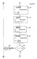
- the method continues its steps and calculates the grain wear factor r S in block 97 using equation (25).
- the contact area A K is calculated using equation (30) and in block 103, using the equation (29), the individual grain force F K is finally calculated.
- decision block 104 it is checked whether the individual grain force F K is less than or equal to a permissible single grain force F K perm. If this is not the case, in other words if the load on the individual grain is too high, the central process variable, namely the related chip removal volume Q ′ wi, is decremented by the amount ⁇ Q ′ wi in block 105, the decrementing amount ⁇ Q wi being equal to that of block 96 or can be dimensioned differently. In this case, too, the program returns to point 84 via the loop in order to continue calculating with the decremented value for Q ′ wi and until the individual grain force F K has dropped to the permissible value F kzul .
- the related time span volume Q w ' determined at the yes output of block 95 can then be converted with the aid of blocks 81 and 82 into a maximum infeed a max of the grinding wheel 18, which is then naturally smaller than the amount which occurred when the inventive method was first run through Procedure at the output of block 82 was determined.
- the method according to the invention is also run through the second loop up to block 104 and if, on the basis of the twice decremented reference chip volume Q w 'present at the output of block 104, a correspondingly twice reduced oversize a is determined, its specification leads to one during real grinding Camshaft 12 for a grinding process that also takes into account the restriction of the individual grain load.
- the roughness depth is used as a restriction criterion with the aid of equation (36), and a value of the related chip removal volume Q ′ w1 is calculated therefrom.
- decision block 107 it is now checked whether the value Q w1 ′ determined in this way is greater than or equal to that currently applied Process value Q ′ wi , which was determined after the process had been carried out up to block 83 and possibly up to block 95 and / or up to block 104.
- this new value Q wi ' must be specified via block 108 as a new process parameter for Q wi 'if the roughness depth is to be taken into account as a restriction criterion.
- the next restriction criterion is the temperature T M using equation (41) is taken into account and the corresponding decision is brought about in blocks 117, 118.
- Block 119 determines the next restriction criterion with the aid of equation (42), the machine data with subsequent decision in blocks 120, 121, and in a corresponding manner block 122 uses equation (43) to calculate a further restriction criterion on the basis of machine data with subsequent decision in the blocks 123 and 124.
- the grinding wheel-specific values, d S , W m , K, d K , Z th , l g and V SR are now displayed in the graphic dialog of the menu navigation for the grinding wheel design.
- the determination of the process parameters to be taken into account then ends in block 128 and the values determined are now transferred as operating parameters for the cam shape grinding machine 10 into the NC control unit 25 or its output interfaces of the data lines 27 and 28, in order to now cam the camshaft 12 in to grind the determined shape.
Landscapes
- Engineering & Computer Science (AREA)
- Human Computer Interaction (AREA)
- Manufacturing & Machinery (AREA)
- Physics & Mathematics (AREA)
- General Physics & Mathematics (AREA)
- Automation & Control Theory (AREA)
- Grinding And Polishing Of Tertiary Curved Surfaces And Surfaces With Complex Shapes (AREA)
Applications Claiming Priority (4)
| Application Number | Priority Date | Filing Date | Title |
|---|---|---|---|
| DE3816997 | 1988-05-19 | ||
| DE3816997 | 1988-05-19 | ||
| DE3830854A DE3830854C2 (de) | 1988-05-19 | 1988-09-10 | Verfahren zum Optimieren der Zustellung beim Schleifen von Nocken einer Nockenwelle |
| DE3830854 | 1988-09-10 |
Publications (2)
| Publication Number | Publication Date |
|---|---|
| EP0342528A2 true EP0342528A2 (fr) | 1989-11-23 |
| EP0342528A3 EP0342528A3 (fr) | 1991-04-17 |
Family
ID=25868231
Family Applications (1)
| Application Number | Title | Priority Date | Filing Date |
|---|---|---|---|
| EP19890108527 Withdrawn EP0342528A3 (fr) | 1988-05-19 | 1989-05-11 | Méthode de rectification de cames d'arbre à cames |
Country Status (3)
| Country | Link |
|---|---|
| US (1) | US4905418A (fr) |
| EP (1) | EP0342528A3 (fr) |
| JP (1) | JPH0215963A (fr) |
Cited By (2)
| Publication number | Priority date | Publication date | Assignee | Title |
|---|---|---|---|---|
| DE102009015934A1 (de) * | 2009-04-02 | 2010-10-07 | Dmg Electronics Gmbh | Verfahren und Vorrichtung zum Erzeugen von Steuerdaten zum Steuern eines Werkzeugs an einer Werkzeugmaschine |
| US8538574B2 (en) | 2009-04-02 | 2013-09-17 | Dmg Electronics Gmbh | Method and apparatus for generating control data for controlling a tool on a machine tool |
Families Citing this family (21)
| Publication number | Priority date | Publication date | Assignee | Title |
|---|---|---|---|---|
| DE4103090C1 (fr) * | 1991-02-01 | 1992-08-27 | Erwin 7618 Nordrach De Junker | |
| JP3490534B2 (ja) * | 1995-03-23 | 2004-01-26 | オークマ株式会社 | 非円形工作物の研削加工方法及び装置 |
| US5919081A (en) * | 1996-09-04 | 1999-07-06 | Unova Ip Corporation | Method and apparatus for computer numerically controlled pin grinder gauge |
| DE19748673C1 (de) * | 1997-11-04 | 1999-07-01 | Vollmer Werke Maschf | Maschine zum Bearbeiten von Werkstücken mit Schneidzähnen, insbes. von Sägeblättern |
| GB2346574B (en) * | 1999-02-03 | 2001-09-19 | Unova Uk Ltd | Angle head grinding method and apparatus |
| DE60002497T2 (de) * | 1999-10-27 | 2004-03-25 | Unova U.K. Ltd., Aylesbury | Schleifvorrichtung mit zwei schleifscheiben |
| WO2005068099A1 (fr) * | 2003-12-23 | 2005-07-28 | Diamond Innovations Inc. | Meule pour application de meulage de cylindre et procede de meulage correspondant |
| DE102004009352B4 (de) * | 2004-02-26 | 2006-01-19 | Thyssen Krupp Automotive Ag | Vorrichtung zum Herstellen einer Fertigkontur eines Werkstücks durch Schleifen und Verfahren dazu |
| US7658665B2 (en) * | 2007-10-09 | 2010-02-09 | Saint-Gobain Abrasives, Inc. | Techniques for cylindrical grinding |
| DE102009051586A1 (de) * | 2009-10-20 | 2011-04-28 | Schaudt Mikrosa Gmbh | Schleifmaschine zum Schleifen und Entgraten |
| JP5589717B2 (ja) * | 2010-09-24 | 2014-09-17 | 株式会社ジェイテクト | 研削方法および研削盤 |
| CN102528614A (zh) * | 2011-12-12 | 2012-07-04 | 潘旭华 | 一种非圆磨削加工轮廓精度的控制方法 |
| SE538599C2 (sv) * | 2014-05-23 | 2016-09-27 | Scania Cv Ab | Förfarande för slipning av ett arbetsstycke och förfarande för bestämning av processparametrar |
| CN106181593B (zh) * | 2016-08-31 | 2019-07-16 | 中车青岛四方机车车辆股份有限公司 | 一种轨道车辆侧墙自动化拉丝系统及拉丝工艺 |
| CN106392858B (zh) * | 2016-12-08 | 2019-04-12 | 宇晶机器(长沙)有限公司 | 一种多面抛光机 |
| GB2569307B (en) | 2017-12-12 | 2022-06-29 | Fives Landis Ltd | Machine tools and methods of operation thereof |
| CN108188480B (zh) * | 2018-01-17 | 2020-01-17 | 华侨大学 | 一种磨粒参数化排布锯片的磨粒参数优选设计方法 |
| CN108247554A (zh) * | 2018-01-17 | 2018-07-06 | 华侨大学 | 一种基于磨粒切厚分布约束的砂轮表面磨粒参数优选设计方法 |
| CN117984164B (zh) * | 2024-01-09 | 2025-10-03 | 潮州三环(集团)股份有限公司 | 一种劈刀及研磨工艺 |
| CN120962455B (zh) * | 2025-08-22 | 2026-03-20 | 霖鼎光学(上海)有限公司 | 一种变进给的超精密磨削方法、存储介质及电子设备 |
| CN121199772B (zh) * | 2025-11-27 | 2026-02-03 | 华侨大学 | 凸轮轴非圆轮廓高速磨削的表面质量动态优化方法 |
Family Cites Families (6)
| Publication number | Priority date | Publication date | Assignee | Title |
|---|---|---|---|---|
| DE2822346C2 (de) * | 1978-05-22 | 1985-09-05 | GFM Gesellschaft für Fertigungstechnik und Maschinenbau GmbH, Steyr | Elektrische numerische Programmsteuerung für Kurbelwellenfräsmaschinen und Kurbelwellen-Schleifmaschinen |
| US4423481A (en) * | 1981-05-26 | 1983-12-27 | Rca Corporation | Numerically controlled method of machining cams and other parts |
| US4402161A (en) * | 1981-10-02 | 1983-09-06 | Litton Industrial Products, Inc. | Cylindrical grinding machine |
| JPS6090667A (ja) * | 1983-10-20 | 1985-05-21 | Toyoda Mach Works Ltd | カム研削方法 |
| JPS60172455A (ja) * | 1984-02-17 | 1985-09-05 | Toyoda Mach Works Ltd | クランク軸の研削方法 |
| JPH0632894B2 (ja) * | 1985-03-20 | 1994-05-02 | 豊田工機株式会社 | カム研削装置 |
-
1989
- 1989-05-11 EP EP19890108527 patent/EP0342528A3/fr not_active Withdrawn
- 1989-05-15 US US07/352,127 patent/US4905418A/en not_active Expired - Fee Related
- 1989-05-19 JP JP1124630A patent/JPH0215963A/ja active Pending
Cited By (2)
| Publication number | Priority date | Publication date | Assignee | Title |
|---|---|---|---|---|
| DE102009015934A1 (de) * | 2009-04-02 | 2010-10-07 | Dmg Electronics Gmbh | Verfahren und Vorrichtung zum Erzeugen von Steuerdaten zum Steuern eines Werkzeugs an einer Werkzeugmaschine |
| US8538574B2 (en) | 2009-04-02 | 2013-09-17 | Dmg Electronics Gmbh | Method and apparatus for generating control data for controlling a tool on a machine tool |
Also Published As
| Publication number | Publication date |
|---|---|
| US4905418A (en) | 1990-03-06 |
| JPH0215963A (ja) | 1990-01-19 |
| EP0342528A3 (fr) | 1991-04-17 |
Similar Documents
| Publication | Publication Date | Title |
|---|---|---|
| EP0342528A2 (fr) | Méthode de rectification de cames d'arbre à cames | |
| DE102006061759B4 (de) | Verzahnungsschleifmaschine und Verfahren zum Schleifen eines Werkstücks | |
| DE69127833T2 (de) | Verfahren und vorrichtung zur herstellung gerad- und schrägzahnstirnräder | |
| EP3552744B1 (fr) | Dispositif et procédé de traitement par chanfreinage d'une pièce à usiner | |
| EP3439819B1 (fr) | Procédé de chanfreinage par enlèvement de matière d'une arête frontale de denture d'engrenage et dispositif conçu à cet effet | |
| EP0543079B1 (fr) | Méthode à commande numérique pour meuler la came d'un arbre à cames | |
| DE69732808T2 (de) | Schleifvorrichtung | |
| DE69122247T2 (de) | Verfahren zum schleifen der oberflächen von schneideblättern und schleifscheibe zum ausführen dieses verfahrens | |
| EP3556501B2 (fr) | Procédé de rectification de denture par génération d'une pièce de la roue dentée et machine de rectification dotée d'une commande de rectification de denture par génération d'une pièce de la roue dentée | |
| EP2367656A1 (fr) | Machine-outil et procédé de fabrication de dentures | |
| EP1319457B2 (fr) | Procédé d'usinage de roues dentées essentiellement cylindriques à denture intérieure ou extérieure | |
| EP0631211B1 (fr) | Méthode pour l'usinage en finition des engrenages | |
| EP0311778B1 (fr) | Procédé de finition de flancs de dents bombées en particulier de roues dentées trempées | |
| WO2017097796A1 (fr) | Dispositif et procédé d'ébauchage et d'usinage fin de roues dentées | |
| EP0212338B1 (fr) | Procédé pour l'usinage de la surface d'une came | |
| DE69312838T2 (de) | Verfahren und Vorrichtung zum Schleifen eines Werkstückes | |
| WO2013083231A2 (fr) | Procédé de rectification de pièces dentées et dispositif correspondant | |
| EP1824627B1 (fr) | Procédé et machine pour usiner des logements de paliers d'arbres | |
| DE1954845B2 (de) | Vorrichtung zur optimalen anpassung einer numerisch gesteuerten werkzeugmaschine an den bearbeitungsvorgang eines werkstueckes | |
| EP1144138B1 (fr) | Procede pour meuler au moins une face d'une lame utilisee dans la technique d'enlevement de copeaux, mise en oeuvre de ce procede et meule pour la mise en oeuvre dudit procede | |
| DE3830854C2 (de) | Verfahren zum Optimieren der Zustellung beim Schleifen von Nocken einer Nockenwelle | |
| EP1312445B1 (fr) | Procédé, logiciel et dispositif pour dressage d'une meule pendant le meulage | |
| EP0346425B1 (fr) | Procede de taillage de meules | |
| DE10113301A1 (de) | Verfahren und Vorrichtung zum Schleifen des Verzahnuungsprofils von Abwälzfräsern sowie Abwälzfräser | |
| EP1080843A2 (fr) | Procédé et dispositif pour dressage par commande numérique de la roue de régulation d'une rectifieuse "sans centre" |
Legal Events
| Date | Code | Title | Description |
|---|---|---|---|
| PUAI | Public reference made under article 153(3) epc to a published international application that has entered the european phase |
Free format text: ORIGINAL CODE: 0009012 |
|
| AK | Designated contracting states |
Kind code of ref document: A2 Designated state(s): CH DE FR GB IT LI |
|
| PUAL | Search report despatched |
Free format text: ORIGINAL CODE: 0009013 |
|
| AK | Designated contracting states |
Kind code of ref document: A3 Designated state(s): CH DE FR GB IT LI |
|
| 17P | Request for examination filed |
Effective date: 19910522 |
|
| 17Q | First examination report despatched |
Effective date: 19930826 |
|
| STAA | Information on the status of an ep patent application or granted ep patent |
Free format text: STATUS: THE APPLICATION IS DEEMED TO BE WITHDRAWN |
|
| 18D | Application deemed to be withdrawn |
Effective date: 19940308 |