EP0342502A1 - Attelage automatique pour véhicules ferroviaires - Google Patents
Attelage automatique pour véhicules ferroviaires Download PDFInfo
- Publication number
- EP0342502A1 EP0342502A1 EP89108398A EP89108398A EP0342502A1 EP 0342502 A1 EP0342502 A1 EP 0342502A1 EP 89108398 A EP89108398 A EP 89108398A EP 89108398 A EP89108398 A EP 89108398A EP 0342502 A1 EP0342502 A1 EP 0342502A1
- Authority
- EP
- European Patent Office
- Prior art keywords
- bolt
- coupling
- coupling according
- unlocking
- driver
- Prior art date
- Legal status (The legal status is an assumption and is not a legal conclusion. Google has not performed a legal analysis and makes no representation as to the accuracy of the status listed.)
- Granted
Links
- 230000008878 coupling Effects 0.000 title claims abstract description 48
- 238000010168 coupling process Methods 0.000 title claims abstract description 48
- 238000005859 coupling reaction Methods 0.000 title claims abstract description 48
- 230000006835 compression Effects 0.000 claims abstract description 18
- 238000007906 compression Methods 0.000 claims abstract description 18
- 230000007246 mechanism Effects 0.000 claims description 7
- 230000009471 action Effects 0.000 claims description 3
- 230000001419 dependent effect Effects 0.000 description 2
- 238000000034 method Methods 0.000 description 2
- 230000008569 process Effects 0.000 description 2
- 239000000356 contaminant Substances 0.000 description 1
- 230000035515 penetration Effects 0.000 description 1
- 230000009467 reduction Effects 0.000 description 1
Images


Classifications
-
- B—PERFORMING OPERATIONS; TRANSPORTING
- B61—RAILWAYS
- B61G—COUPLINGS; DRAUGHT AND BUFFING APPLIANCES
- B61G1/00—Couplings comprising interengaging parts of different shape or form and having links, bars, pins, shackles, or hooks as coupling means
- B61G1/40—Couplings comprising interengaging parts of different shape or form and having links, bars, pins, shackles, or hooks as coupling means with coupling bars having an enlarged or recessed end which slips into the opposite coupling part and is gripped thereby, e.g. arrow-head type; with coupling parts having a tong-like gripping action
Definitions
- the invention relates to an automatic clutch for rail vehicles, as characterized in the preamble of claim 1.
- the object of the present invention is to create an automatic clutch of the type mentioned at the outset, in which it is also possible to uncouple under great tensile force with little effort, so that even for a remote-controlled decoupling process not very expensive, electrically acting actuators can be used.
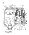
- Fig. 1 shows in cross section one of the two coupling heads of the same type, on the head piece 1 a draw bolt 3 and a draw bolt receptacle 4 is arranged.
- the tension bolt 3 has a tapered bolt head 5, a recess 6 with an end-shaped clamping surface 7 and two cylindrical centering parts 8.
- the draw bolt receptacle 4 has a wear-resistant centering ring 9 arranged in the head piece 1 and a receiving part 10 which is fixedly connected to the head piece 1.
- a locking lever 12 is pivotally mounted on two bolts 11, the nose-shaped closing part 13 of which can be pivoted through openings 14 of the receiving part 10 into the interior 15 thereof.
- the locking lever 12 has a pressure cam 37 with a contact surface 38 in the region of the bearing on the bolt 11.
- the openings 14 are sealed by the contact of the closing lever 12 on seals 44 so that no contaminants can get into the interior of the coupling piece 1 from the draw bolt receptacle 4.
- a frame 16 is mounted displaceably in the direction of the longitudinal axis 17 of the draw bolt receptacle 4 or the draw bolt 3 of the second coupling head and surrounds the receiving part 10 with the locking levers 12.
- the frame 16 each has a contact contour 18 which interacts with the locking levers 12.
- Two guide bolts 40 are fastened to the frame 16, on which a cross member 19 is mounted so as to be displaceable relative to the frame 16 against the pressure of springs 39.
- a push rod 20 Coaxial to the longitudinal axis 17 is a push rod 20 which is inserted through a bore in the cross member 19, one end 21 of which sticks in a bore 22 of the receiving part 10 and extends into its interior 15 and the other end 23 in a blind hole 24 of the rear piece 2 is led.
- guide rods 28 are fastened on both sides of the push rod, the free end of which are guided in blind holes 29 of the rear piece 2 and on which compression springs 30 are arranged on the rear piece 2 and on the crossbar 19.
- a bolt 32 is arranged on the cross member 19 so as to be pivotable about the bolt 31 and has a lever arm 33 above and below the cross member 19 and the push rod 20, each with a recess 34 and a stop surface 35. Between the cross member 19 and the bolt 32 tension springs 36 are arranged above and below, which press the bolt 32 against the driver 25, so that their pins 26 are held in the recesses 34.
- a lifting magnet 45 is arranged in the rear piece 2, to which an unlocking rod 41 is provided, which is provided with a collar 42 forming a stop surface, the direction of movement of which extends preferably transversely to the longitudinal axis 17.
- Solenoid valves controllable compressed air cylinders or an electric motor with reduction gear can be used.
- An active part 43 is arranged in the rear part 2 to the side of the push rod 20 and is actuated by a linkage (not shown). The pivoting movement of the active part 43 preferably runs transversely to the longitudinal axis 17.
- Fig. 1 shows the coupling head in the ready-to-couple state, wherein the crossbar 19 is pressed against the pressure cams 37 of the locking lever 12 by the pressure of the springs 30, so that they rest in a sealed position on the receiving part 10.
- the frame 16 and the push rod 20 are in the direction of the draw bolt receptacle in the end position, which is also brought about by the compression springs 30 and the compression spring 27.
- the locking levers 12 are pivoted outwards by the conical shape of the bolt head until they rest on the cylindrical part of the bolt head 5.
- the crossbeam 19 is pushed back by the pressure cams 37 of the locking lever 12 by a small amount (approx. 2 mm), the compression springs 27 and 30 also being compressed by the amount and pulling the frame 16 with the prestressing force of the compression springs 39.
- the cross member 19 When retracting further, the bolt head 5 comes to rest against the front end 21 of the push rod 20 and pushes it back, the cross member 19 also being displaced via the attachments 26 of the driver 25 and the bolt 32 arranged on the cross member 19, whereby this is done by the compression springs 27 and 30 formed spring accumulator 50 is further tensioned.
- the cross member 19 pulls the frame 16 via the springs 39 until it is held by the locking levers 12 on its inclined part 18a of the contact contours 18.
- the couplings are precisely aligned or centered by the centering part 8 of the tension bolt 3 and the centering ring 9.
- Locking lever (12) H: h is preferably 3: 1.
- Fig. 4 shows the clutch in the unlocked and uncoupled position, the couplings have not yet been pulled apart.
- unlocking takes place either from the driver's cab of the train by remote control by switching on the solenoid 45 or an air cylinder or geared motor or by manual actuation of the active part 43.
- the force required for unlocking the unlocking rod is thereby significantly reduced compared to the tensile force acting on the draw bolt.
- the arrangement according to the invention of a spring accumulator makes it possible for it to be charged when coupling and to release its energy when uncoupling, in order to return the locking mechanism to the "ready to couple” position.
- the locking lever When engaged, the locking lever is securely locked by the frame.
Landscapes
- Engineering & Computer Science (AREA)
- Mechanical Engineering (AREA)
- Automotive Seat Belt Assembly (AREA)
- Mechanical Operated Clutches (AREA)
- Machines For Laying And Maintaining Railways (AREA)
- Quick-Acting Or Multi-Walled Pipe Joints (AREA)
- Clamps And Clips (AREA)
- Lock And Its Accessories (AREA)
- Fittings On The Vehicle Exterior For Carrying Loads, And Devices For Holding Or Mounting Articles (AREA)
- Soil Working Implements (AREA)
Priority Applications (1)
| Application Number | Priority Date | Filing Date | Title |
|---|---|---|---|
| AT89108398T ATE72546T1 (de) | 1988-05-18 | 1989-05-10 | Selbsttaetige kupplung fuer schienenfahrzeuge. |
Applications Claiming Priority (2)
| Application Number | Priority Date | Filing Date | Title |
|---|---|---|---|
| CH1879/88A CH675864A5 (fr) | 1988-05-18 | 1988-05-18 | |
| CH1879/88 | 1988-05-18 |
Publications (2)
| Publication Number | Publication Date |
|---|---|
| EP0342502A1 true EP0342502A1 (fr) | 1989-11-23 |
| EP0342502B1 EP0342502B1 (fr) | 1992-02-12 |
Family
ID=4220723
Family Applications (1)
| Application Number | Title | Priority Date | Filing Date |
|---|---|---|---|
| EP89108398A Expired - Lifetime EP0342502B1 (fr) | 1988-05-18 | 1989-05-10 | Attelage automatique pour véhicules ferroviaires |
Country Status (10)
| Country | Link |
|---|---|
| US (1) | US4927035A (fr) |
| EP (1) | EP0342502B1 (fr) |
| JP (1) | JPH0755657B2 (fr) |
| AT (1) | ATE72546T1 (fr) |
| AU (1) | AU622661B2 (fr) |
| CH (1) | CH675864A5 (fr) |
| CZ (1) | CZ289289A3 (fr) |
| DE (1) | DE58900824D1 (fr) |
| ES (1) | ES2029544T3 (fr) |
| SU (1) | SU1743346A3 (fr) |
Cited By (1)
| Publication number | Priority date | Publication date | Assignee | Title |
|---|---|---|---|---|
| EP0972693A3 (fr) * | 1998-07-01 | 2000-10-25 | Schwab Verkehrstechnik AG | Mécanisme de verrouillage pour un dispositif d'accouplement |
Families Citing this family (13)
| Publication number | Priority date | Publication date | Assignee | Title |
|---|---|---|---|---|
| US5775524A (en) * | 1996-03-25 | 1998-07-07 | Kadee Quality Products Co. | Remote uncoupling mechanism |
| US8408406B2 (en) * | 2008-05-22 | 2013-04-02 | Bedloe Industries Llc | Central datum feature on railroad coupler body and corresponding gauges |
| US8544662B2 (en) * | 2008-05-22 | 2013-10-01 | Bedloe Industries Llc | Central datum feature on railroad coupler body and corresponding gauges |
| BRPI0913124A2 (pt) * | 2008-05-22 | 2017-06-20 | Bedloe Ind Llc | aperfeiçoamento de um corpo do dispositivo de acoplamento ferroviário para aperfeiçoar a rotação da articulação de pino |
| CN102083670B (zh) * | 2008-05-23 | 2015-08-19 | 贝德洛工业公司 | 用于实现所得转向节的增加的强度及疲劳寿命的铁道耦合器芯结构 |
| CN102083671B (zh) | 2008-05-23 | 2016-03-23 | 贝德洛工业公司 | 由枢轴销与肾形芯和经隔离指形芯形成的转向节 |
| BRPI0913946A2 (pt) | 2008-05-23 | 2015-10-20 | Bedloe Ind Llc | junta articulada sem um núcleo de dedo |
| US8601068B2 (en) * | 2008-06-26 | 2013-12-03 | Ca, Inc. | Information technology system collaboration |
| US8714377B2 (en) | 2011-02-04 | 2014-05-06 | Wabtec Holding Corp. | Energy absorbing coupler |
| US8960464B2 (en) | 2011-04-08 | 2015-02-24 | Wabtec Holding Corp. | Coupler support mechanism |
| US8616389B2 (en) * | 2012-05-10 | 2013-12-31 | Wabtec Holding Corp. | Over-center spring coupler |
| KR20150132243A (ko) | 2013-03-22 | 2015-11-25 | 웹텍 홀딩 코포레이션 | 자동화된 커플러 포지셔닝 디바이스 |
| CN110641505B (zh) * | 2019-06-27 | 2020-10-23 | 温州承玥机械设备有限公司 | 基于煤矿工程的煤炭矿车的脱销装置 |
Citations (3)
| Publication number | Priority date | Publication date | Assignee | Title |
|---|---|---|---|---|
| DE456632C (de) * | 1927-04-17 | 1928-02-29 | Hermann An Huef Jun | Elektrische Eisenbahnwagenkupplung |
| DE468478C (de) * | 1927-02-24 | 1928-11-15 | Georg Michl Dr | Selbsttaetige starre Mittelpufferkupplung fuer Eisenbahnfahrzeuge |
| DE554398C (de) * | 1931-04-25 | 1932-07-07 | Heinrich Eichler | Selbsttaetige Doppelkupplung |
Family Cites Families (3)
| Publication number | Priority date | Publication date | Assignee | Title |
|---|---|---|---|---|
| US506598A (en) * | 1893-10-10 | Johann theodor koch | ||
| JPS5329882A (en) * | 1976-09-01 | 1978-03-20 | Sumiko Ookouchi | Method of producing body of bottleware |
| US4703862A (en) * | 1985-05-02 | 1987-11-03 | Werner George S | Automatic railroad car coupler |
-
1988
- 1988-05-18 CH CH1879/88A patent/CH675864A5/de not_active IP Right Cessation
-
1989
- 1989-05-04 AU AU34032/89A patent/AU622661B2/en not_active Ceased
- 1989-05-10 DE DE8989108398T patent/DE58900824D1/de not_active Expired - Fee Related
- 1989-05-10 AT AT89108398T patent/ATE72546T1/de not_active IP Right Cessation
- 1989-05-10 ES ES198989108398T patent/ES2029544T3/es not_active Expired - Lifetime
- 1989-05-10 EP EP89108398A patent/EP0342502B1/fr not_active Expired - Lifetime
- 1989-05-15 CZ CS892892A patent/CZ289289A3/cs unknown
- 1989-05-17 US US07/353,347 patent/US4927035A/en not_active Expired - Fee Related
- 1989-05-18 SU SU894614164A patent/SU1743346A3/ru active
- 1989-05-18 JP JP1125490A patent/JPH0755657B2/ja not_active Expired - Lifetime
Patent Citations (3)
| Publication number | Priority date | Publication date | Assignee | Title |
|---|---|---|---|---|
| DE468478C (de) * | 1927-02-24 | 1928-11-15 | Georg Michl Dr | Selbsttaetige starre Mittelpufferkupplung fuer Eisenbahnfahrzeuge |
| DE456632C (de) * | 1927-04-17 | 1928-02-29 | Hermann An Huef Jun | Elektrische Eisenbahnwagenkupplung |
| DE554398C (de) * | 1931-04-25 | 1932-07-07 | Heinrich Eichler | Selbsttaetige Doppelkupplung |
Cited By (1)
| Publication number | Priority date | Publication date | Assignee | Title |
|---|---|---|---|---|
| EP0972693A3 (fr) * | 1998-07-01 | 2000-10-25 | Schwab Verkehrstechnik AG | Mécanisme de verrouillage pour un dispositif d'accouplement |
Also Published As
| Publication number | Publication date |
|---|---|
| DE58900824D1 (de) | 1992-03-26 |
| CZ289289A3 (en) | 1993-08-11 |
| US4927035A (en) | 1990-05-22 |
| EP0342502B1 (fr) | 1992-02-12 |
| SU1743346A3 (ru) | 1992-06-23 |
| CH675864A5 (fr) | 1990-11-15 |
| JPH0218158A (ja) | 1990-01-22 |
| ATE72546T1 (de) | 1992-02-15 |
| AU3403289A (en) | 1989-11-23 |
| JPH0755657B2 (ja) | 1995-06-14 |
| AU622661B2 (en) | 1992-04-16 |
| ES2029544T3 (es) | 1992-08-16 |
Similar Documents
| Publication | Publication Date | Title |
|---|---|---|
| EP0342502B1 (fr) | Attelage automatique pour véhicules ferroviaires | |
| EP3689705B1 (fr) | Attelage automatique de trains | |
| DE102021132991A1 (de) | Automatische Zugkupplung und Verfahren zum Entkuppeln einer automatischen Zugkupplung | |
| DE69507395T2 (de) | Ein höhenverstellbarer Zughaken für Sattelkupplungen | |
| EP4263319A2 (fr) | Attelage de traction automatique | |
| EP4330110A1 (fr) | Attelage automatique simple traction et procédé de désattelage d'un attelage automatique simple traction | |
| EP4330109A1 (fr) | Accouplement de traction automatique et procédé de désaccouplement d'un accouplement de traction automatique | |
| EP2285510B1 (fr) | PRESSE COMPRENANT UN DISPOSITIF DE TRANSFERT POUR avancer LES PIÈCES PAS À PAS ET avec UN dispositif d' ACCOUPLEMENT des barres de préhension | |
| WO2021185497A1 (fr) | Agencement d'accouplement | |
| DE3407526C2 (fr) | ||
| DE60013314T2 (de) | Kupplungsanordnung für schienenfahrzeuge | |
| DE102020119328A1 (de) | Automatische Zugkupplung und Schienenfahrzeugrahmen mit einer automatischen Zugkupplung | |
| WO2015121290A1 (fr) | Tête de couplage d'un attelage automatique à tampon central | |
| EP0471875B1 (fr) | Wagon à marchandises | |
| DE102022104693A1 (de) | Automatische zugkupplung sowie verfahren zum betreiben einer automatischen zugkupplung | |
| DE3204406C2 (fr) | ||
| WO2023160923A1 (fr) | Accouplement de train automatique, véhicule guidé sur rail comprenant un tel accouplement de train automatique, et procédé de désaccouplement de deux accouplements de train automatiques qui sont accouplés l'un à l'autre | |
| DE2922458C2 (fr) | ||
| EP0243758A2 (fr) | Attelage automatique pour véhicules ferroviaires | |
| CH674964A5 (fr) | ||
| EP4155161A1 (fr) | Accouplement, notamment pour un véhicule ferroviaire | |
| DE4310741A1 (de) | Automatische Kupplung für Schienenfahrzeuge | |
| DE3823247A1 (de) | Selbsttaetig kuppelnde zugkupplung fuer schienenfahrzeuge | |
| DE9409992U1 (de) | Automatische Stangenkupplung | |
| DE3543049A1 (de) | Verfahren und vorrichtung zum entkuppeln von anhaengevorrichtungen an foerderwagen in bergbaubetrieben |
Legal Events
| Date | Code | Title | Description |
|---|---|---|---|
| PUAI | Public reference made under article 153(3) epc to a published international application that has entered the european phase |
Free format text: ORIGINAL CODE: 0009012 |
|
| 17P | Request for examination filed |
Effective date: 19890510 |
|
| AK | Designated contracting states |
Kind code of ref document: A1 Designated state(s): AT BE CH DE ES FR GB GR IT LI LU NL SE |
|
| 17Q | First examination report despatched |
Effective date: 19910722 |
|
| GRAA | (expected) grant |
Free format text: ORIGINAL CODE: 0009210 |
|
| AK | Designated contracting states |
Kind code of ref document: B1 Designated state(s): AT BE CH DE ES FR GB GR IT LI LU NL SE |
|
| PG25 | Lapsed in a contracting state [announced via postgrant information from national office to epo] |
Ref country code: GR Free format text: LAPSE BECAUSE OF FAILURE TO SUBMIT A TRANSLATION OF THE DESCRIPTION OR TO PAY THE FEE WITHIN THE PRESCRIBED TIME-LIMIT Effective date: 19920212 |
|
| REF | Corresponds to: |
Ref document number: 72546 Country of ref document: AT Date of ref document: 19920215 Kind code of ref document: T |
|
| ET | Fr: translation filed | ||
| REF | Corresponds to: |
Ref document number: 58900824 Country of ref document: DE Date of ref document: 19920326 |
|
| GBT | Gb: translation of ep patent filed (gb section 77(6)(a)/1977) | ||
| ITF | It: translation for a ep patent filed | ||
| PG25 | Lapsed in a contracting state [announced via postgrant information from national office to epo] |
Ref country code: LU Free format text: LAPSE BECAUSE OF NON-PAYMENT OF DUE FEES Effective date: 19920531 |
|
| REG | Reference to a national code |
Ref country code: ES Ref legal event code: FG2A Ref document number: 2029544 Country of ref document: ES Kind code of ref document: T3 |
|
| PLBE | No opposition filed within time limit |
Free format text: ORIGINAL CODE: 0009261 |
|
| STAA | Information on the status of an ep patent application or granted ep patent |
Free format text: STATUS: NO OPPOSITION FILED WITHIN TIME LIMIT |
|
| 26N | No opposition filed | ||
| REG | Reference to a national code |
Ref country code: FR Ref legal event code: TP |
|
| REG | Reference to a national code |
Ref country code: CH Ref legal event code: PUE Owner name: SECHERON S.A. |
|
| EAL | Se: european patent in force in sweden |
Ref document number: 89108398.2 |
|
| PGFP | Annual fee paid to national office [announced via postgrant information from national office to epo] |
Ref country code: GB Payment date: 19970410 Year of fee payment: 9 |
|
| PGFP | Annual fee paid to national office [announced via postgrant information from national office to epo] |
Ref country code: FR Payment date: 19970411 Year of fee payment: 9 |
|
| PGFP | Annual fee paid to national office [announced via postgrant information from national office to epo] |
Ref country code: BE Payment date: 19970417 Year of fee payment: 9 |
|
| PGFP | Annual fee paid to national office [announced via postgrant information from national office to epo] |
Ref country code: AT Payment date: 19970422 Year of fee payment: 9 |
|
| PGFP | Annual fee paid to national office [announced via postgrant information from national office to epo] |
Ref country code: SE Payment date: 19970423 Year of fee payment: 9 |
|
| PGFP | Annual fee paid to national office [announced via postgrant information from national office to epo] |
Ref country code: NL Payment date: 19970428 Year of fee payment: 9 |
|
| PGFP | Annual fee paid to national office [announced via postgrant information from national office to epo] |
Ref country code: ES Payment date: 19970519 Year of fee payment: 9 |
|
| PGFP | Annual fee paid to national office [announced via postgrant information from national office to epo] |
Ref country code: DE Payment date: 19970521 Year of fee payment: 9 |
|
| PGFP | Annual fee paid to national office [announced via postgrant information from national office to epo] |
Ref country code: CH Payment date: 19970526 Year of fee payment: 9 |
|
| PG25 | Lapsed in a contracting state [announced via postgrant information from national office to epo] |
Ref country code: GB Free format text: LAPSE BECAUSE OF NON-PAYMENT OF DUE FEES Effective date: 19980510 Ref country code: AT Free format text: LAPSE BECAUSE OF NON-PAYMENT OF DUE FEES Effective date: 19980510 |
|
| PG25 | Lapsed in a contracting state [announced via postgrant information from national office to epo] |
Ref country code: SE Free format text: LAPSE BECAUSE OF NON-PAYMENT OF DUE FEES Effective date: 19980511 Ref country code: ES Free format text: LAPSE BECAUSE OF EXPIRATION OF PROTECTION Effective date: 19980511 |
|
| PG25 | Lapsed in a contracting state [announced via postgrant information from national office to epo] |
Ref country code: LI Free format text: LAPSE BECAUSE OF NON-PAYMENT OF DUE FEES Effective date: 19980531 Ref country code: FR Free format text: LAPSE BECAUSE OF NON-PAYMENT OF DUE FEES Effective date: 19980531 Ref country code: CH Free format text: LAPSE BECAUSE OF NON-PAYMENT OF DUE FEES Effective date: 19980531 Ref country code: BE Free format text: LAPSE BECAUSE OF NON-PAYMENT OF DUE FEES Effective date: 19980531 |
|
| BERE | Be: lapsed |
Owner name: S.A. SECHERON Effective date: 19980531 |
|
| PG25 | Lapsed in a contracting state [announced via postgrant information from national office to epo] |
Ref country code: NL Free format text: LAPSE BECAUSE OF NON-PAYMENT OF DUE FEES Effective date: 19981201 |
|
| GBPC | Gb: european patent ceased through non-payment of renewal fee |
Effective date: 19980510 |
|
| REG | Reference to a national code |
Ref country code: CH Ref legal event code: PL |
|
| EUG | Se: european patent has lapsed |
Ref document number: 89108398.2 |
|
| NLV4 | Nl: lapsed or anulled due to non-payment of the annual fee |
Effective date: 19981201 |
|
| PG25 | Lapsed in a contracting state [announced via postgrant information from national office to epo] |
Ref country code: DE Free format text: LAPSE BECAUSE OF NON-PAYMENT OF DUE FEES Effective date: 19990302 |
|
| REG | Reference to a national code |
Ref country code: FR Ref legal event code: ST |
|
| REG | Reference to a national code |
Ref country code: ES Ref legal event code: FD2A Effective date: 20000201 |
|
| PG25 | Lapsed in a contracting state [announced via postgrant information from national office to epo] |
Ref country code: IT Free format text: LAPSE BECAUSE OF NON-PAYMENT OF DUE FEES;WARNING: LAPSES OF ITALIAN PATENTS WITH EFFECTIVE DATE BEFORE 2007 MAY HAVE OCCURRED AT ANY TIME BEFORE 2007. THE CORRECT EFFECTIVE DATE MAY BE DIFFERENT FROM THE ONE RECORDED. Effective date: 20050510 |