EP0342401A2 - Dispositif pour déclencher un système de sécurité passif - Google Patents
Dispositif pour déclencher un système de sécurité passif Download PDFInfo
- Publication number
- EP0342401A2 EP0342401A2 EP89107534A EP89107534A EP0342401A2 EP 0342401 A2 EP0342401 A2 EP 0342401A2 EP 89107534 A EP89107534 A EP 89107534A EP 89107534 A EP89107534 A EP 89107534A EP 0342401 A2 EP0342401 A2 EP 0342401A2
- Authority
- EP
- European Patent Office
- Prior art keywords
- circuit
- threshold
- gate
- output
- safety device
- Prior art date
- Legal status (The legal status is an assumption and is not a legal conclusion. Google has not performed a legal analysis and makes no representation as to the accuracy of the status listed.)
- Granted
Links
Images


Classifications
-
- B—PERFORMING OPERATIONS; TRANSPORTING
- B60—VEHICLES IN GENERAL
- B60R—VEHICLES, VEHICLE FITTINGS, OR VEHICLE PARTS, NOT OTHERWISE PROVIDED FOR
- B60R21/00—Arrangements or fittings on vehicles for protecting or preventing injuries to occupants or pedestrians in case of accidents or other traffic risks
- B60R21/01—Electrical circuits for triggering passive safety arrangements, e.g. airbags, safety belt tighteners, in case of vehicle accidents or impending vehicle accidents
- B60R21/013—Electrical circuits for triggering passive safety arrangements, e.g. airbags, safety belt tighteners, in case of vehicle accidents or impending vehicle accidents including means for detecting collisions, impending collisions or roll-over
- B60R21/0132—Electrical circuits for triggering passive safety arrangements, e.g. airbags, safety belt tighteners, in case of vehicle accidents or impending vehicle accidents including means for detecting collisions, impending collisions or roll-over responsive to vehicle motion parameters, e.g. to vehicle longitudinal or transversal deceleration or speed value
- B60R21/0133—Electrical circuits for triggering passive safety arrangements, e.g. airbags, safety belt tighteners, in case of vehicle accidents or impending vehicle accidents including means for detecting collisions, impending collisions or roll-over responsive to vehicle motion parameters, e.g. to vehicle longitudinal or transversal deceleration or speed value by integrating the amplitude of the input signal
-
- B—PERFORMING OPERATIONS; TRANSPORTING
- B60—VEHICLES IN GENERAL
- B60R—VEHICLES, VEHICLE FITTINGS, OR VEHICLE PARTS, NOT OTHERWISE PROVIDED FOR
- B60R21/00—Arrangements or fittings on vehicles for protecting or preventing injuries to occupants or pedestrians in case of accidents or other traffic risks
- B60R21/01—Electrical circuits for triggering passive safety arrangements, e.g. airbags, safety belt tighteners, in case of vehicle accidents or impending vehicle accidents
- B60R21/013—Electrical circuits for triggering passive safety arrangements, e.g. airbags, safety belt tighteners, in case of vehicle accidents or impending vehicle accidents including means for detecting collisions, impending collisions or roll-over
- B60R21/0132—Electrical circuits for triggering passive safety arrangements, e.g. airbags, safety belt tighteners, in case of vehicle accidents or impending vehicle accidents including means for detecting collisions, impending collisions or roll-over responsive to vehicle motion parameters, e.g. to vehicle longitudinal or transversal deceleration or speed value
Definitions
- the invention relates to a device for triggering a passive safety device in vehicles according to the preamble of the first claim.
- DE-OS 37 17 427 two accelerometers (1 and 2) are additionally connected to an acceleration evaluation circuit (13, 14 and 16, 15).
- the acceleration evaluation circuits each have two different threshold values (Ref. 1 and Ref. 2) and both threshold values are reached in the event of a critical impact by the vehicle.
- first and second threshold values are sufficient for triggering, a rear or side impact can be clearly distinguished from a front or oblique impact. Only in the latter two types of impact are the low second threshold values in both channels exceeded. Only then is the safety device triggered. With a rear or Side impact, the low second threshold values are not exceeded at least in one channel, so that the safety device is then not triggered either.
- this known device In addition to the differentiation between different types of impact, this known device also makes it possible to take into account the design of different types of vehicles, in particular in the area of the crumple zones, so that the safety device is reliably triggered for each type of vehicle in the event of a critical impact.
- the invention is based on the object of improving a device of the type in question, on the one hand to reliably differentiate between different types of impact and on the other hand to be able to adapt the device to different driving conditions of the vehicle.
- a refined logic is proposed with which the output signals of the individual signal channels can be evaluated in a variety of ways.
- several threshold value switches with different threshold values are provided in each threshold value circuit, these threshold values being selected so that the safety device can be triggered in different driving situations.
- Which of the threshold switches actually triggers is determined in an evaluation circuit and a logic with the aid of which signals from all channels are evaluated and, based on this evaluation, blocking and release signals are emitted, which then release or release a specific signal path within the device up to the circuit breaker of the safety device . lock.
- the individual signal channels preferably have a single or double integrator circuit as the evaluation circuit and are preferably equipped with two threshold value switches, one threshold value being set relatively low and the other threshold value being set relatively high.
- the evaluation circuit determines which of these two threshold values should be used for a possible triggering of the safety device.
- the integrated signals in the individual channels and / or the output signals of the accelerometers are used directly in the evaluation circuit, possibly after smoothing and signal shaping.
- This evaluation enables a clear identification of whether the output signals of the accelerometers are to be assigned to an impact or are due to other circumstances. The latter can e.g. be the case when the vehicle is traveling over an extremely poor distance, through potholes, over a curb or the like.
- Situations can also be identified in which the accelerometer is subjected to such high mechanical loads for a short time, e.g. in the event of a hammer blow that the safety device would be triggered without an evaluation. However, this must be prevented in any case.
- the evaluation circuit can contain, for example, an AND link in which the output signals of the accelerometers are independent of one another with a relatively low threshold value are compared and / or an OR operation in which the output signals of the accelerometers are compared independently of one another with a relatively high threshold value. If, in one of the comparisons, an output signal is generated according to the logic logic gates, the inputs that are assigned to the threshold value switches with a low threshold value in the individual signal channels are enabled in the logic, for example.
- the signals of the individual signal channels which have already been integrated are preferably fed independently of one another to a threshold value switch, each with a pulse extension element connected downstream.
- the outputs of the pulse extension elements are connected to a comparison and time circuit which, for a certain time after the start of the impact, enables the inputs of the logic assigned to the threshold switches with low threshold values and then blocks them, so that then only the output signals of the threshold switches with higher threshold values.
- the output signals of the accelerometers can also be used to clearly identify a rear impact or a hammer blow, for example.
- the signals from the accelerometers are inverted via an integrator circuit.
- the output signals of these integrator circuits are combined in a common OR gate, the output signal of which blocks the circuit breaker for triggering the safety device in the event of a rear-end collision.
- the output signals of each accelerometer are sampled at short time intervals, the instantaneous value at the end of such a time interval is compared with the minimum value that occurred within this time interval. If high differences are found in this comparison, a time circuit is used to check whether these high differences occur within a certain time interval, which indicates a mechanical load on the accelerometer that is not caused by an impact. In this case, the circuit breaker for the safety device is also blocked.
- the instantaneous threshold value which is effective for triggering the safety device can always be selected such that in the event of a collision of the vehicle in which the safety device must be triggered to protect the vehicle occupants, it is triggered at the earliest possible time in is locked in other situations.
- the adaptability of the device to different vehicle types, different driving situations and different types of impacts can be optimized in this way.
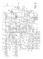
- the block diagram in Figure 2 shows a device referred to as an impact sensor 1 for triggering a safety device, not shown, of a motor vehicle, e.g. an air cushion or a belt tensioner.
- the impact sensor 1 has two accelerometers 2 and 3, e.g. two piezoelectric sensors, each with a directional sensitivity axis, which is designated A1 and A2 in FIG. 1.
- the sensitivity axes are set at an angle + or - against the longitudinal axis of a motor vehicle 4, the direction of travel of which is indicated by the arrow P. In this case the angle is 45 °.
- Accelerometers 2 and 3 each respond in a region around these sensitivity axes in accordance with a cosine characteristic, this region being identified by the four circles in FIG. 1.
- the output signals of the two accelerometers 2 and 3 are evaluated in signal channels 5 and 6 of the same structure. Only the signal channel 5 for the accelerometer 2 is described below:
- the output signal of the accelerometer 2 is amplified in an amplifier 7, shaped in a filter 8 and its amplitude is limited in an asymmetrical limiter 9 above a positive amplitude Sal and below a negative amplitude Sa2.
- a reference value Sa3 which is supplied by a reference value transmitter 11, is subtracted from the output signal obtained in this way, which corresponds to an acceleration of the sensor 2, in a differential element 10.
- the output signal of the differential element 10 is fed to an integrator 12 and in integrated into this.
- the output of the integrator 12, the signal of which corresponds to a speed, is connected to a threshold circuit 13 with two threshold switches 13 and 14 lying in parallel with a relatively low threshold value Sv2 and a second higher threshold value Sv3.
- the two threshold values are selected such that when the integrated output signal exceeds them, the safety device can be triggered under certain conditions. Which of the two threshold values is to act at the moment or whether the triggering of the safety device is to be blocked is decided by an evaluation circuit described below.
- the output of the threshold switch 13 is connected via an input line L1 to a trigger circuit constructed as a logic gate circuit 15.
- the output signal of the threshold switch 14 is combined with signals from the evaluation circuit, as explained further below.
- the said evaluation circuit is composed of several subcircuits, namely a response circuit, a start and selection circuit, two acceleration evaluation circuits, a rear impact evaluation circuit and a so-called hammer blow evaluation circuit.
- the response circuit is intended to ensure that the safety device is only triggered when there are significant signals in both signal channels 5 and 6, from which at least the possibility of a front or angled impact from the front can be concluded. For this purpose, signals in both signal channels must be linked together.
- a third threshold switch 21 is connected to a threshold value Svl, this threshold value being less than the lowest threshold value which triggers the safety device, ie lower than Sv2.
- This third threshold switch 21 is followed by a pulse extender 22, which extends the output signal of the threshold switch 21 to a time period St1.
- the signal channel 5 is linked to the signal channel 6, so that here the integrator 12 of the first signal channel 5 is connected to a threshold switch 21 'with the threshold value Sv1 and the same arrangement of a pulse extender 22' and an AND gate 23 ' .
- the input lines for the gate circuit 15, which carry signals generated in the same way, are labeled L2 'and L6'.
- the start of an impact of the vehicle is determined and one of the threshold values is also selected.
- the outputs of the integrators 12 and 12 ' are each connected to a threshold switch 31 and 31', each of which has the threshold value Sv4.
- This threshold is set in the range between the threshold Svl and Sv2, ie it is also lower than that for an off solution of the safety device suitable lowest threshold value Sv2.
- Both threshold switches 31, 31 ' are each followed by a pulse extender 32 or 32', which extend the pulse emitted by the associated threshold switch by a certain period of time St3.
- the outputs of these pulse extenders are connected to the two inputs of an AND gate 33, the output of which is connected to an edge-controlled timer 34, which emits a signal after a period of time St2 after activation.
- the output of the timer 34 is fed to an input of an OR gate 35, which in turn is followed by a resettable FLIP-FLOP 36.
- An input line L5 leading to the gate circuit 15 is connected to its output.
- the output of the AND gate 33 is also connected to an input of the OR gate 37 and its output to the inputs of two timing elements 38 and 39, respectively.
- the output signal of the timing element 38 is a HIGH signal when there is no activation, but it drops to a LOW signal after activation after a very short period of time St7.
- the output signals of this timer are fed to the gate circuit 15 via an input line L7.
- the second timing element 39 serves as a reset element for the timing element 38 and the FLIP-FLOP 36. After a relatively long period of time after activation, this timing element 39 emits a reset signal to the timing element 38 and the FLIP-FLOP 36 and sets them in their respective initial state back. This period is longer than the total operating time of the safety device in the event of an impact.
- the outputs of the differential elements 10 and 10 ' are each connected to two threshold switches 41 and 51 or 41' and 51 ', the threshold values of which are Sa4 and Sa5, respectively. These threshold values are chosen such that they are practically only reached in the event of an impact.
- the outputs of the two threshold switches 41 and 41 ' are connected to the inputs of the two pulse extenders 42 and 42'. Their outputs are connected to the two inputs of an AND gate 43 and its output is connected to an input of the OR gate 44.
- the outputs of the two threshold switches 51 and 51 ' are connected to the two inputs of an OR gate 52 and its output is connected to a pulse extender 53 which adjusts the output signal of the OR gate 52 to a time period St5. This time period is thus the same as the time period of the pulse extender 42 or 42 '. However, this condition does not have to be met.
- the output of the pulse extender 53 is fed to the second input of the mentioned OR gate 44, to the output of which an input line L3 for the gate circuit 15 is connected.
- This circuit is intended to prevent the passive safety device from being triggered in the event of a rear-end collision.
- the outputs of the asymmetrical limiter 9 and 9 ' are each guided to the input of an inverting amplifier 61 or 61', so that the negative output signals of the accelerometers 2 and 3 occurring in a rear-end collision are converted to positive signals.
- Each inverting amplifier 61, 61 ' is followed by a differential element 62 or 62' tet, with which a reference value transmitter 63 or 63 'is connected.
- a reference value transmitter 63 or 63 ' is connected.
- the signals are then integrated in an integrator 64 or 64 ', which is followed by a threshold switch 65 or 65' with a threshold value Sv5.
- the signals are therefore evaluated according to the same principle as in the signal channels 5 and 6.
- the output of the OR gate 66 is connected on the one hand to an input line L8 leading to the gate circuit 15 and on the other hand to a pulse length doubler 67 which doubles the pulse length, however, always emits a pulse of at least a minimum duration when activated.
- the output of this pulse length doubler is connected to an input line L4 which also leads to the gate circuit 15.
- This circuit is intended to prevent the passive safety device from being triggered in the workshop in the event of a short-term mechanical load, for example in the event of a hammer blow.
- the outputs of the unbalanced limiters 9 and 9 ' are each connected to the input of a holding and sampling circuit 71 and 71', in which within a short period St9 the end value reached at the end of this period with the previous minimum within this period Value is compared.
- the output signals of these sample and hold circuits are each fed to a threshold switch and compared there with a threshold Sa6.
- the outputs of the threshold switches 72 and 72 ' are linked together in an OR gate 73, the output of which is connected to the second input of the above OR gate 37 is connected.
- the output of the OR gate 73 is also led to an input of an AND gate 74, at the second input of which the output signal of the timing element 38 is present.
- the output of the AND gate 74 is connected to the second input of the OR gate 35.
- the gate circuit 15 serving as a trigger circuit for the passive safety device has two AND gates 81 and 81 'with five inputs, an OR gate 82 with four inputs linking the outputs of the AND gates 81 and 81' and a circuit breaker for the passive safety device leading AND gate 83 with three inputs.
- the AND gate 81 With the five inputs of the AND gate 81, the input lines L1, L2, L3, L4 and L5 are connected, with the five inputs of the second AND gate 81 'the input lines L1', L2 ', L3, L4 and L5.
- the four inputs for the OR gate 82 are at the respective output of the AND gates 81 and 81 ', the other two inputs are connected to the input lines L6 and L6'.
- One input of the AND gate 83 is connected to the output of the OR gate 82, the other two inputs to the input lines L7 and L8, the signals carried thereon being inverted in the AND gate 83.
- the accelerometer 2 emits a signal which exceeds the reference value Sa3 and is thus integrated in the integrator 12. If the integrated signal exceeds the threshold Sv2, there is a HIGH signal at the first input of the AND gate 81. However, the AND gate 81 only switches on and thus triggers the safety device, even if a HIGH signal is also present at the other four inputs and, furthermore, the two input lines L7 and L8 connected to the AND gate 83 carry a LOW signal.
- the A Gear line L2 only carries a HIGH signal during the period St1 after triggering the pulse extender 22, ie only when the integrated signals in both signal channels 5 and 6 reach the low threshold Sv1 and thus both accelerometers 2 and 3 receive a significant signal. If the threshold value Sv1 is not reached in only one channel, the AND gate 81 cannot switch through either. Such a case can occur, for example, if there is a side impact.
- the AND gate 81 can also only turn on when the input line L3 carries a HIGH signal. This means that at least one of the two acceleration evaluation circuits must output an output signal, i.e. either that the lower acceleration threshold Sa4 has been reached in both channels or that the higher acceleration threshold Sa5 has been exceeded in at least one channel.
- the fourth input line L4 only carries a HIGH signal if no rear impact has been detected in the rear impact assessment circuit, i.e. only if there is no signal at the input of the inverting pulse length doubler 67.
- the input signal of the pulse length doubler is also on line L8, so that the LOW signal enables the third input of AND gate 83. If a rear-end collision were detected, the output signal of the inverting pulse length doubler became a LOW signal, so that the AND gate 81 is not released. Likewise, the AND gate 83 would then be blocked by the HIGH signal at the output of the OR gate 66 through the inversion.
- the signal on input line L5 must be a HIGH signal. With the flip-flop 36, this is always the case in the event of an impact, during that with the timing element 34 predetermined time period St2. The prerequisite here is that the integrated signals in both signal channels 5 and 6 reach the threshold value Sv4, that is, significant signals must be present in both channels for the AND gate 81 to be switched through.
- the signal on the input line L7 must then be a LOW signal, ie after the start of an impact, which is detected by an output signal from the AND gate 33, the time period St7 must first have elapsed. During this period, the output signal of the pulse extender 38, which is usually LOW, switches to HIGH and thus blocks the AND gate 83 for this period. This blocking effect is also achieved if only a short hammer blow pulse is detected.
- the AND gate 81 is blocked by the flip-flop 36 via the input line L5 which now carries a LOW signal.
- the safety device can only be triggered if a HIGH signal is present at the OR gate 82 via the line L6 and the two input lines L7 and L8 carry a LOW signal.
- a HIGH signal on the input line L6 only occurs, however, if there is also a HIGH signal at both inputs of the AND gate 23, that is to say if the integrated output signal of the integrator 12 exceeds the threshold value Sv3 of the threshold value switch 14 and at the same time within that by the Pulse extender 22 predetermined time period St1 the integrated output signal of the integrator 12 'exceeds the low threshold Sv1. Also in this Traps must therefore have significant signals in both channels.
- the AND gate 81 can also be blocked during the time period St2 predetermined by the pulse extender 34, so that the passive safety device can only be triggered via the OR gate 82.
- the AND gate 81 is blocked by the LOW signal on the input line L2. Likewise, blocking can take place if no relevant output signal occurs in the acceleration evaluation circuits either at the output of the AND gate 43 or at the output of the pulse extender 53.
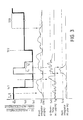
- FIG. 3 A schematic representation of the possible threshold value changes is shown in FIG. 3.
- the two threshold values Sv2 and Sv3 suitable for triggering the passive safety device are indicated, and the symbol also indicates the blocking of the entire device.
- This lock is always given during normal driving, since the AND gates 81 and 81 ', the OR gate 82 and the AND gate 83 are locked in the gate circuit.
- 3 is on the abscissa of the individual signal diagrams Time entered. At time zero, an impact is detected in the AND gate 33, since the integrated output signals in the signal channels 5 and 6 exceed the threshold value Sv4 predetermined by the threshold switches 31 and 31 '.
- the second line of the signal diagram in FIG. 3 only the integrated output signal of a signal channel is shown.
- the impact sensor 1 After detection of the zero point, the impact sensor 1 remains blocked for the short period of time St7 predetermined by the timer 38, since the associated input line L7 carries a HIGH signal during this period and the AND gate 83 blocks. Only after this release does one of the two threshold values Sv2 or Sv3 take effect, depending on the criteria specified above. In this case, it is assumed that the threshold Sv3 takes effect.
- the high acceleration threshold Sa5 is exceeded in the impact sensor 1 in one of the signal channels, which is shown in the third line of the signal diagram in FIG. 3, as a result of which the effective threshold is set to the threshold value Sv2.
- the threshold value is raised to, ie the entire collision sensor is blocked. This is done for the duration of the pulse delivered by the OR gate 66.
- the threshold value is then lowered to the larger threshold value Sv3, since the output signal of the pulse length doubler 67 blocks the two AND gates 81 and 81 'in the gate circuit 15.
- the higher threshold value Sv3 becomes effective for the impact sensor. If the integrated output signal in the signal channels 5 and 6 falls below the threshold value Sv4, then after the period St8, the entire impact sensor is replaced by the inverse Tiert reset signal of the timer 39 in the initial state.
- the course of the threshold values in the top line in FIG. 3 does not correspond to the actual course, in particular not during an impact, but only serves to demonstrate the switching options between the individual thresholds.
- a variety of other combinations are possible.
- the circuit described for the impact sensor can also be implemented differently.
Landscapes
- Engineering & Computer Science (AREA)
- Mechanical Engineering (AREA)
- Air Bags (AREA)
- Automotive Seat Belt Assembly (AREA)
- Switches Operated By Changes In Physical Conditions (AREA)
Applications Claiming Priority (2)
| Application Number | Priority Date | Filing Date | Title |
|---|---|---|---|
| DE3816587A DE3816587A1 (de) | 1988-05-16 | 1988-05-16 | Einrichtung zur ausloesung einer passiven sicherheitseinrichtung |
| DE3816587 | 1988-05-16 |
Publications (3)
| Publication Number | Publication Date |
|---|---|
| EP0342401A2 true EP0342401A2 (fr) | 1989-11-23 |
| EP0342401A3 EP0342401A3 (fr) | 1991-08-07 |
| EP0342401B1 EP0342401B1 (fr) | 1994-03-30 |
Family
ID=6354433
Family Applications (1)
| Application Number | Title | Priority Date | Filing Date |
|---|---|---|---|
| EP89107534A Expired - Lifetime EP0342401B1 (fr) | 1988-05-16 | 1989-04-26 | Dispositif pour déclencher un système de sécurité passif |
Country Status (4)
| Country | Link |
|---|---|
| US (1) | US5173614A (fr) |
| EP (1) | EP0342401B1 (fr) |
| JP (1) | JP2785133B2 (fr) |
| DE (1) | DE3816587A1 (fr) |
Cited By (12)
| Publication number | Priority date | Publication date | Assignee | Title |
|---|---|---|---|---|
| WO1990009298A1 (fr) * | 1989-02-18 | 1990-08-23 | Robert Bosch Gmbh | Procede pour liberer des moyens de retenue |
| EP0531989A1 (fr) * | 1991-09-11 | 1993-03-17 | Toyota Jidosha Kabushiki Kaisha | Système de senseurs de collision latérale pour airbag latéral |
| EP0693404A3 (fr) * | 1994-07-21 | 1996-11-13 | Telefunken Microelectron | Procédé pour déclencher des sacs à air latéraux d'un dispositif de sécurité passif dans un véhicule automobile |
| EP0748725A1 (fr) * | 1995-06-15 | 1996-12-18 | Trw Inc. | Procédé et appareil pour fournir une fonction de sécurité pour système de détection d'un choc latéral |
| US5692775A (en) * | 1994-12-22 | 1997-12-02 | Trw Inc. | Method and apparatus for controlling an occupant restraint system in response to selected criteria zone |
| WO1998018662A1 (fr) * | 1996-10-31 | 1998-05-07 | Siemens Aktiengesellschaft | Systeme de commande pour systeme de protection pour les occupants d'un vehicule contre les chocs lateraux |
| USRE36122E (en) * | 1989-02-18 | 1999-03-02 | Robert Bosch Gmbh | Method for controlling the release of passenger restraint systems |
| US6460882B1 (en) | 1999-01-07 | 2002-10-08 | Siemens Vdo Automotive Corporation | Airbag actuation event discrimination system and method |
| EP1438216B1 (fr) * | 2001-10-25 | 2006-07-05 | Bayerische Motoren Werke Aktiengesellschaft | Procede de declenchement d'un moyen de retenue des occupants d'un vehicule |
| EP2045144A1 (fr) * | 2007-10-02 | 2009-04-08 | Continental Automotive GmbH | Procédé de reconnaissance d'une face de collision lors de la collision frontale |
| CN103507735A (zh) * | 2012-06-26 | 2014-01-15 | 罗伯特·博世有限公司 | 识别、诊断和触发人员保护装置的触发装置的方法及装置 |
| WO2018149663A1 (fr) * | 2017-02-14 | 2018-08-23 | Robert Bosch Gmbh | Circuit destiné à mettre en œuvre une comparaison |
Families Citing this family (75)
| Publication number | Priority date | Publication date | Assignee | Title |
|---|---|---|---|---|
| US5483447A (en) * | 1988-09-17 | 1996-01-09 | Robert Bosch Gmbh | Apparatus for tripping a system for the protection of occupants of a vehicle |
| WO1990003289A1 (fr) * | 1988-09-17 | 1990-04-05 | Robert Bosch Gmbh | Appareil et procede de declenchement d'un systeme de protection pour les occupants d'un vehicule |
| US5225985A (en) * | 1989-01-24 | 1993-07-06 | Diesel Kiki Co., Ltd. | Vehicle safety device actuating apparatus with adaptive reference level |
| DE3942011C3 (de) * | 1989-12-20 | 1996-10-17 | Telefunken Microelectron | Einrichtung zur Auslösung einer passiven Sicherheitseinrichtung für Fahrzeuginsassen |
| DE4005444A1 (de) * | 1990-02-21 | 1991-08-22 | Bayerische Motoren Werke Ag | Verfahren und vorrichtung zur unterstuetzung eines kraftfahrers bei einem fahrspurwechsel |
| DE4128230C2 (de) * | 1990-08-24 | 1997-01-09 | Kanto Seiki Co | Steuersystem für einen in einem Kraftfahrzeug angebrachten Airbag |
| US5787377A (en) * | 1990-08-24 | 1998-07-28 | Kanto Seiki Co. Ltd. | Air-bag control circuit |
| US6125313A (en) * | 1990-08-24 | 2000-09-26 | Kanto Seiki Co., Ltd. | Air-bag control circuit |
| DE4029195C2 (de) * | 1990-09-14 | 1996-09-26 | Telefunken Microelectron | Aufprallsensor |
| DE4116336C1 (en) * | 1991-05-18 | 1992-06-11 | Messerschmitt-Boelkow-Blohm Gmbh, 8012 Ottobrunn, De | Passive safety device release assembly for motor vehicle occupant - has acceleration pick=ups with sensitivity axes directed to detect angle of frontal impact and supplying evaluating circuit |
| DE4117811A1 (de) * | 1991-05-31 | 1992-12-03 | Messerschmitt Boelkow Blohm | Verfahren zur aufprallerkennung bei fahrzeugen |
| EP0517253B1 (fr) * | 1991-06-07 | 1995-09-27 | Kansei Corporation | Dispositif de retenue du passager d'un véhicule automobile ou analogue |
| US7284769B2 (en) * | 1995-06-07 | 2007-10-23 | Automotive Technologies International, Inc. | Method and apparatus for sensing a vehicle crash |
| US6609053B1 (en) * | 1995-06-07 | 2003-08-19 | Automotive Technologies International, Inc. | Method and apparatus for sensing a vehicle crash |
| US5684701A (en) * | 1995-06-07 | 1997-11-04 | Automotive Technologies International, Inc. | Method and apparatus for sensing a vehicle crash |
| US6532408B1 (en) | 1997-05-29 | 2003-03-11 | Automotive Technologies International, Inc. | Smart airbag system |
| US5337238A (en) * | 1991-10-08 | 1994-08-09 | Automotive Systems Laboratory, Inc. | System and method for actuating vehicle safety device using damped measures |
| US5490066A (en) * | 1992-04-27 | 1996-02-06 | Automotive Systems Laboratory, Inc. | Method for discriminating long-period, low-velocity crashes |
| JP2793084B2 (ja) * | 1992-05-29 | 1998-09-03 | 三菱電機株式会社 | 乗員保護装置の起動装置 |
| JPH0640308A (ja) * | 1992-07-21 | 1994-02-15 | Naldec Kk | 車両の安全装置 |
| JPH0672282A (ja) * | 1992-08-28 | 1994-03-15 | Tokai Rika Co Ltd | 車両の緊急状態判定装置 |
| US5495414A (en) * | 1993-04-07 | 1996-02-27 | Ford Motor Company | Integrated silicon automotive accelerometer and single-point impact sensor |
| US5446661A (en) * | 1993-04-15 | 1995-08-29 | Automotive Systems Laboratory, Inc. | Adjustable crash discrimination system with occupant position detection |
| US5506775A (en) * | 1993-05-20 | 1996-04-09 | Kansei Corporation | Power source circuit for an occupant protecting device of motor vehicles |
| JP3324220B2 (ja) * | 1993-09-07 | 2002-09-17 | 日産自動車株式会社 | 乗員拘束装置の制御装置 |
| US5461567A (en) * | 1994-03-04 | 1995-10-24 | Delco Electronics Corporation | Supplemental inflatable restraint system having a rear impact algorithm for seat belt pretensioner |
| US5538099A (en) * | 1994-05-27 | 1996-07-23 | Trw Vehicle Safety Systems Inc. | Method and apparatus for controlling an air bag restraint system |
| DE4420114A1 (de) * | 1994-06-09 | 1995-12-14 | Telefunken Microelectron | Auslöseeinrichtung für Personenschutzvorrichtungen in Fahrzeugen |
| US5484166A (en) * | 1994-07-22 | 1996-01-16 | Trw Vehicle Safety Systems Inc. | Method and apparatus for providing a deployment signal for a vehicle occupant restraint device during a side impact crash |
| US5583771A (en) * | 1994-08-04 | 1996-12-10 | Delco Electronics Corp. | Method and apparatus for distinguishing between deployment events and non-deployment events in an SIR system |
| JP3050061B2 (ja) * | 1994-10-25 | 2000-06-05 | トヨタ自動車株式会社 | 乗員拘束装置 |
| KR100202941B1 (ko) * | 1994-10-31 | 1999-06-15 | 배길훈 | 3방향(3축) 감속신호를 이용한 자동차용 충돌유형 판별장치 |
| KR970001747B1 (ko) * | 1994-10-31 | 1997-02-15 | 대우전자 주식회사 | 3방향(3축) 감속신호와 가변 기준치를 이용한 자동차용 에어백 제어장치 |
| JPH08246512A (ja) * | 1995-03-07 | 1996-09-24 | Shinwa Musen Syst Kk | 漏水検知器具 |
| US5995892A (en) * | 1995-06-12 | 1999-11-30 | Denso Corporation | Triggering device for safety apparatus |
| JP3011092B2 (ja) * | 1995-06-12 | 2000-02-21 | 株式会社デンソー | 安全装置の起動装置 |
| DE19537546B4 (de) * | 1995-10-09 | 2004-12-02 | Conti Temic Microelectronic Gmbh | Aufprallerkennungsvorrichtung, insbesondere für ein Sicherheitssystem für Fahrzeuge zur Personenbeförderung |
| JP2973902B2 (ja) * | 1995-11-06 | 1999-11-08 | トヨタ自動車株式会社 | 乗員保護装置の起動制御装置 |
| US5684336A (en) * | 1996-03-04 | 1997-11-04 | Trw Inc. | Crash sensor assembly including both an inertia sensor and an accelerometer and method |
| DE19619412C1 (de) * | 1996-05-14 | 1997-08-28 | Telefunken Microelectron | Auslöseverfahren für passive Sicherheitseinrichtungen in Fahrzeugen |
| DE19619414C1 (de) * | 1996-05-14 | 1997-08-21 | Telefunken Microelectron | Auslöseverfahren für passive Sicherheitseinrichtungen in Fahrzeugen |
| US6070113A (en) * | 1996-06-21 | 2000-05-30 | Automotive Systems Laboratory, Inc. | Hybrid vehicle crash discrimination system |
| US6023664A (en) * | 1996-10-16 | 2000-02-08 | Automotive Systems Laboratory, Inc. | Vehicle crash sensing system |
| DE59802762D1 (de) * | 1997-10-02 | 2002-02-21 | Siemens Ag | Vorrichtung für den insassenschutz in einem kraftfahrzeug |
| DE19807124A1 (de) * | 1998-02-20 | 1999-09-02 | Bosch Gmbh Robert | Verfahren und Vorrichtung zum Auslösen eines Rückhaltesystems |
| JPH11344503A (ja) * | 1998-06-02 | 1999-12-14 | Akebono Brake Ind Co Ltd | エアバッグ用補助加速度センサ装置 |
| DE19955551A1 (de) * | 1998-11-19 | 2000-05-25 | Inova Gmbh Tech Entwicklungen | Airbagvorrichtung und Auslöseverfahren dafür |
| DE19854366C1 (de) | 1998-11-25 | 2000-04-06 | Daimler Chrysler Ag | Verfahren zur Anpassung einer Auslöseschwelle von Insassenschutzeinrichtungen |
| US6591932B1 (en) * | 1998-12-21 | 2003-07-15 | J. B. Drummond | Sensing system for vehicle passive restrants |
| JP2000255373A (ja) * | 1999-03-02 | 2000-09-19 | Mitsubishi Electric Corp | 車両衝突検出装置 |
| DE10022173C2 (de) | 2000-05-06 | 2003-07-03 | Conti Temic Microelectronic | Verfahren zur Auslösung von Insassenschutzeinrichtungen |
| US6249730B1 (en) | 2000-05-19 | 2001-06-19 | Trw, Inc. | Vehicle occupant protection system and method utilizing Z-axis central safing |
| EP1299267B1 (fr) | 2000-07-07 | 2004-05-19 | Siemens Aktiengesellschaft | Systeme de retenue de passager pour vehicule automobile |
| DE10050956A1 (de) * | 2000-10-13 | 2002-05-02 | Bayerische Motoren Werke Ag | Verfahren zur Auslösung von wenigstens einem Rückhaltemittel |
| US6553295B1 (en) | 2000-10-24 | 2003-04-22 | Ford Global Technologies, Inc. | System for sensing a side impact collision |
| DE10119621A1 (de) * | 2001-04-21 | 2002-10-24 | Daimler Chrysler Ag | Datenbussystem für Sensoren eines Insassenschutzsystems |
| US6520536B2 (en) * | 2001-05-04 | 2003-02-18 | Trw Inc. | Method and apparatus for controlling an occupant side restraining device with enhanced side safing function |
| JP4037129B2 (ja) * | 2002-02-27 | 2008-01-23 | カルソニックカンセイ株式会社 | 多重通信装置及びそれを用いた乗員保護装置 |
| CA2433598C (fr) | 2002-06-25 | 2009-07-28 | Honda Giken Kogyo Kabushiki Kaisha | Systeme de determination des collisions |
| JP2006503757A (ja) * | 2002-10-21 | 2006-02-02 | オートリブ ディヴェロプメント アクチボラゲット | 自動車の安全機構における又はそれに関連する改善 |
| ITTO20030142A1 (it) * | 2003-02-28 | 2004-09-01 | St Microelectronics Srl | Dispositivo inerziale multidirezinale a soglia multipla |
| GB2403935A (en) * | 2003-07-17 | 2005-01-19 | Autoliv Dev | Crash detection system with accelerometers at an angle to a vehicles longitudinal axis |
| DE102004032985A1 (de) * | 2004-07-08 | 2006-02-09 | Daimlerchrysler Ag | Kraftfahrzeug mit einem präventiv wirkenden Sicherheitssystem |
| DE102005015568A1 (de) * | 2005-04-05 | 2006-10-12 | Robert Bosch Gmbh | Vorrichtung zur Aufprallerkennung |
| US7840325B2 (en) * | 2005-06-30 | 2010-11-23 | Trw Automotive U.S. Llc | Method and apparatus for controlling a front actuatable restraining device using side satellite safing sensors |
| DE102007029764A1 (de) * | 2006-06-27 | 2008-01-03 | Conti Temic Microelectronic Gmbh | Vorrichtung und Verfahren zur Sensierung einer gerichteten physikalischen Größe |
| DE102006049121B3 (de) * | 2006-10-18 | 2008-02-07 | Siemens Ag | Unfallerkennungsvorrichtung mit redundant angeordneten Beschleunigungssensoren zur Frontalaufprallerkennung in einem Kraftfahrzeug |
| KR100853188B1 (ko) * | 2006-12-08 | 2008-08-20 | 한국전자통신연구원 | Rfid 시스템에서의 전원 차단 장치 및 방법 |
| US20080173107A1 (en) * | 2007-01-19 | 2008-07-24 | Autoliv Asp, Inc. | Combination pressure and acceleration sensor |
| DE102008011165B4 (de) * | 2008-02-26 | 2017-05-04 | Autoliv Development Ab | Sensoranordnung für ein Insassenschutzsystem eines Kraftfahrzeugs |
| KR101081070B1 (ko) * | 2009-10-07 | 2011-11-07 | 한국과학기술원 | 전방충돌 가속도 센서에 대한 충돌 신호 처리 장치 |
| US20120239247A1 (en) * | 2011-03-16 | 2012-09-20 | General Dynamics Land Systems, Inc. | Systems and methods for active mitigation of sudden accelerative forces in vehicles |
| DE102014202666B4 (de) * | 2014-02-13 | 2024-05-23 | Robert Bosch Gmbh | Verfahren und Vorrichtung zum Auslösen zumindest eines Personenschutzmittels eines Fahrzeugs |
| DE102016222082A1 (de) * | 2016-11-10 | 2018-05-17 | Robert Bosch Gmbh | Verfahren zur Ansteuerung einer Personen-Schutzvorrichtung |
| US11034318B2 (en) * | 2019-06-04 | 2021-06-15 | B/E Aerospace, Inc. | Safety system initiator with electronically adjustable fire time |
Family Cites Families (9)
| Publication number | Priority date | Publication date | Assignee | Title |
|---|---|---|---|---|
| US3762495A (en) * | 1970-07-04 | 1973-10-02 | Nissan Motor | Method and device for triggering motor vehicle safety mechanisms |
| US3778823A (en) * | 1970-12-27 | 1973-12-11 | Toyota Motor Co Ltd | Vehicle safety device |
| DE2612215C2 (de) * | 1976-03-23 | 1989-02-23 | Messerschmitt-Bölkow-Blohm GmbH, 8000 München | Vorrichtung zum Auslösen passiver Insassenschutzsysteme für Fahrzeuge bei deren Aufprall |
| DE2920147A1 (de) * | 1979-05-18 | 1980-12-11 | Volkswagenwerk Ag | Anordnung mit einem elektrodynamischen beschleunigungssensor und einer auswerteschaltung |
| FR2467740A1 (fr) * | 1979-10-23 | 1981-04-30 | Renault | Systeme de detection de collisions et de commande de dispositif de securite |
| FR2504474A1 (fr) * | 1981-04-28 | 1982-10-29 | Renault | Procede et systeme de detection de collision et de commande de dispositifs de securite |
| DE3413768C1 (de) * | 1984-04-12 | 1985-07-11 | Daimler-Benz Ag, 7000 Stuttgart | Passives Insassenrueckhaltesystem |
| DE3425281A1 (de) * | 1984-07-10 | 1986-01-16 | Robert Bosch Gmbh, 7000 Stuttgart | Schaltungsanordnung zur registrierung von fehlerhaften ausloesesignalen fuer ein rueckhaltesystem |
| DE3717427C3 (de) * | 1987-05-23 | 1994-09-01 | Deutsche Aerospace | Aufprallsensor für Kraftfahrzeuge |
-
1988
- 1988-05-16 DE DE3816587A patent/DE3816587A1/de active Granted
-
1989
- 1989-04-26 EP EP89107534A patent/EP0342401B1/fr not_active Expired - Lifetime
- 1989-05-16 US US07/352,928 patent/US5173614A/en not_active Expired - Lifetime
- 1989-05-16 JP JP1120572A patent/JP2785133B2/ja not_active Expired - Fee Related
Cited By (19)
| Publication number | Priority date | Publication date | Assignee | Title |
|---|---|---|---|---|
| WO1990009298A1 (fr) * | 1989-02-18 | 1990-08-23 | Robert Bosch Gmbh | Procede pour liberer des moyens de retenue |
| US5014810A (en) * | 1989-02-18 | 1991-05-14 | Robert Bosch Gmbh | Method for controlling the release of passenger restraint systems |
| USRE36122E (en) * | 1989-02-18 | 1999-03-02 | Robert Bosch Gmbh | Method for controlling the release of passenger restraint systems |
| EP0531989A1 (fr) * | 1991-09-11 | 1993-03-17 | Toyota Jidosha Kabushiki Kaisha | Système de senseurs de collision latérale pour airbag latéral |
| US5338062A (en) * | 1991-09-11 | 1994-08-16 | Toyota Jidosha Kabushiki Kaisha | Side collision sensor system for side airbag apparatus |
| EP0693404A3 (fr) * | 1994-07-21 | 1996-11-13 | Telefunken Microelectron | Procédé pour déclencher des sacs à air latéraux d'un dispositif de sécurité passif dans un véhicule automobile |
| US5692775A (en) * | 1994-12-22 | 1997-12-02 | Trw Inc. | Method and apparatus for controlling an occupant restraint system in response to selected criteria zone |
| US5758899A (en) * | 1995-06-15 | 1998-06-02 | Trw Inc. | Method and apparatus for providing a safing function for side impact crash sensing systems |
| EP0748725A1 (fr) * | 1995-06-15 | 1996-12-18 | Trw Inc. | Procédé et appareil pour fournir une fonction de sécurité pour système de détection d'un choc latéral |
| WO1998018662A1 (fr) * | 1996-10-31 | 1998-05-07 | Siemens Aktiengesellschaft | Systeme de commande pour systeme de protection pour les occupants d'un vehicule contre les chocs lateraux |
| US6256562B1 (en) | 1996-10-31 | 2001-07-03 | Siemens Aktiengesellschaft | Control configuration for an occupant protection system for side collision protection in a vehicle |
| US6460882B1 (en) | 1999-01-07 | 2002-10-08 | Siemens Vdo Automotive Corporation | Airbag actuation event discrimination system and method |
| EP1438216B1 (fr) * | 2001-10-25 | 2006-07-05 | Bayerische Motoren Werke Aktiengesellschaft | Procede de declenchement d'un moyen de retenue des occupants d'un vehicule |
| EP2045144A1 (fr) * | 2007-10-02 | 2009-04-08 | Continental Automotive GmbH | Procédé de reconnaissance d'une face de collision lors de la collision frontale |
| CN103507735A (zh) * | 2012-06-26 | 2014-01-15 | 罗伯特·博世有限公司 | 识别、诊断和触发人员保护装置的触发装置的方法及装置 |
| WO2018149663A1 (fr) * | 2017-02-14 | 2018-08-23 | Robert Bosch Gmbh | Circuit destiné à mettre en œuvre une comparaison |
| CN110248848A (zh) * | 2017-02-14 | 2019-09-17 | 罗伯特·博世有限公司 | 用于执行比较的电路组件 |
| US11077808B2 (en) | 2017-02-14 | 2021-08-03 | Robert Bosch Gmbh | Circuit assemblage for carrying out a comparison |
| CN110248848B (zh) * | 2017-02-14 | 2022-09-16 | 罗伯特·博世有限公司 | 用于执行比较的电路组件 |
Also Published As
| Publication number | Publication date |
|---|---|
| EP0342401B1 (fr) | 1994-03-30 |
| JPH0218134A (ja) | 1990-01-22 |
| JP2785133B2 (ja) | 1998-08-13 |
| DE3816587C2 (fr) | 1991-08-22 |
| US5173614A (en) | 1992-12-22 |
| DE3816587A1 (de) | 1989-11-23 |
| EP0342401A3 (fr) | 1991-08-07 |
Similar Documents
| Publication | Publication Date | Title |
|---|---|---|
| EP0342401B1 (fr) | Dispositif pour déclencher un système de sécurité passif | |
| EP0464033B1 (fr) | Appareil de commande de systemes de retenue de passagers et/ou de securite pour vehicules | |
| EP0807558B1 (fr) | Procédé de déclenchement d'un système de sécurité passif dans un véhicule | |
| DE3942011C3 (de) | Einrichtung zur Auslösung einer passiven Sicherheitseinrichtung für Fahrzeuginsassen | |
| DE2123359C3 (de) | Auslösevorrichtung für eine Sicherheitsvorrichtung für die Insassen eines Kraftfahrzeuges | |
| DE19645952C2 (de) | Steueranordnung für ein Rückhaltemittel in einem Kraftfahrzeug | |
| DE4116336C1 (en) | Passive safety device release assembly for motor vehicle occupant - has acceleration pick=ups with sensitivity axes directed to detect angle of frontal impact and supplying evaluating circuit | |
| EP0292669B2 (fr) | Détecteur de collision pour les véhicules automobiles | |
| EP2318238B1 (fr) | Procédé et appareil de commande destinés à commander des moyens de protection des personnes pour un véhicule | |
| DE112007002666B4 (de) | Aktivierungsvorrichtung für ein Insassenschutzsystem | |
| EP0810129B1 (fr) | Procédé de déclenchement d'un système de sécurité passif dans un véhicule | |
| EP0830271B1 (fr) | Dispositif de commande pour declencher un dispositif de retenue sur un vehicule en cas de choc lateral | |
| DE19707307A1 (de) | Verbesserte Aufpralldetektoranordnung | |
| DE4425846A1 (de) | Verfahren zur Auslösung von Seitenairbags einer passiven Sicherheitseinrichtung für Kraftfahrzeuge | |
| DE19623520B4 (de) | Auslösevorrichtung für eine Sicherheitsvorrichtung | |
| EP1140564B1 (fr) | Systeme de commande pour moyens de protection pour passagers d'une automobile | |
| DE19537546B4 (de) | Aufprallerkennungsvorrichtung, insbesondere für ein Sicherheitssystem für Fahrzeuge zur Personenbeförderung | |
| DE3816588C2 (fr) | ||
| DE3816589C2 (fr) | ||
| DE3816591C2 (fr) | ||
| DE3704331C2 (de) | Einrichtung zur Erfassung eines Frontalaufpralls eines Fahrzeugs | |
| EP1409298B2 (fr) | Dispositif et procede pour declencher un moyen de protection d'occupant d'un vehicule automobile | |
| DE19616836C2 (de) | Einrichtung zum Auslösen eines Rückhaltemittels in einem Fahrzeug | |
| DE19719453B4 (de) | Vorrichtung zum Steuern eines Insassenschutzmittels zum Frontaufprallschutz sowie eines Insassenschutzmittels zum Heckaufprallschutz in einem Kraftfahrzeug | |
| DE102005011103A1 (de) | Verfahren und Vorrichtung zum Erkennen eines Überrollvorgangs |
Legal Events
| Date | Code | Title | Description |
|---|---|---|---|
| PUAI | Public reference made under article 153(3) epc to a published international application that has entered the european phase |
Free format text: ORIGINAL CODE: 0009012 |
|
| AK | Designated contracting states |
Kind code of ref document: A2 Designated state(s): FR GB IT SE |
|
| 17P | Request for examination filed |
Effective date: 19910118 |
|
| PUAL | Search report despatched |
Free format text: ORIGINAL CODE: 0009013 |
|
| AK | Designated contracting states |
Kind code of ref document: A3 Designated state(s): FR GB IT SE |
|
| 17Q | First examination report despatched |
Effective date: 19920813 |
|
| RAP1 | Party data changed (applicant data changed or rights of an application transferred) |
Owner name: DEUTSCHE AEROSPACE AKTIENGESELLSCHAFT |
|
| GRAA | (expected) grant |
Free format text: ORIGINAL CODE: 0009210 |
|
| AK | Designated contracting states |
Kind code of ref document: B1 Designated state(s): FR GB IT SE |
|
| PG25 | Lapsed in a contracting state [announced via postgrant information from national office to epo] |
Ref country code: SE Free format text: THE PATENT HAS BEEN ANNULLED BY A DECISION OF A NATIONAL AUTHORITY Effective date: 19940330 |
|
| ET | Fr: translation filed | ||
| GBT | Gb: translation of ep patent filed (gb section 77(6)(a)/1977) |
Effective date: 19940506 |
|
| ITF | It: translation for a ep patent filed | ||
| RAP2 | Party data changed (patent owner data changed or rights of a patent transferred) |
Owner name: TEMIC TELEFUNKEN MICROELECTRONIC GMBH |
|
| REG | Reference to a national code |
Ref country code: GB Ref legal event code: 732E |
|
| REG | Reference to a national code |
Ref country code: FR Ref legal event code: TP |
|
| PLBE | No opposition filed within time limit |
Free format text: ORIGINAL CODE: 0009261 |
|
| STAA | Information on the status of an ep patent application or granted ep patent |
Free format text: STATUS: NO OPPOSITION FILED WITHIN TIME LIMIT |
|
| 26N | No opposition filed | ||
| REG | Reference to a national code |
Ref country code: GB Ref legal event code: IF02 |
|
| PGFP | Annual fee paid to national office [announced via postgrant information from national office to epo] |
Ref country code: GB Payment date: 20040331 Year of fee payment: 16 |
|
| PGFP | Annual fee paid to national office [announced via postgrant information from national office to epo] |
Ref country code: FR Payment date: 20040415 Year of fee payment: 16 |
|
| PG25 | Lapsed in a contracting state [announced via postgrant information from national office to epo] |
Ref country code: IT Free format text: LAPSE BECAUSE OF NON-PAYMENT OF DUE FEES Effective date: 20050426 Ref country code: GB Free format text: LAPSE BECAUSE OF NON-PAYMENT OF DUE FEES Effective date: 20050426 |
|
| GBPC | Gb: european patent ceased through non-payment of renewal fee |
Effective date: 20050426 |
|
| PG25 | Lapsed in a contracting state [announced via postgrant information from national office to epo] |
Ref country code: FR Free format text: LAPSE BECAUSE OF NON-PAYMENT OF DUE FEES Effective date: 20051230 |
|
| REG | Reference to a national code |
Ref country code: FR Ref legal event code: ST Effective date: 20051230 |