EP0342304A2 - Vorrichtung zum Absperren der Verschlusselemente eines Nutzfahrzeugaufbaus - Google Patents
Vorrichtung zum Absperren der Verschlusselemente eines Nutzfahrzeugaufbaus Download PDFInfo
- Publication number
- EP0342304A2 EP0342304A2 EP88830497A EP88830497A EP0342304A2 EP 0342304 A2 EP0342304 A2 EP 0342304A2 EP 88830497 A EP88830497 A EP 88830497A EP 88830497 A EP88830497 A EP 88830497A EP 0342304 A2 EP0342304 A2 EP 0342304A2
- Authority
- EP
- European Patent Office
- Prior art keywords
- pillar
- eyelet
- locking
- bolt
- sector
- Prior art date
- Legal status (The legal status is an assumption and is not a legal conclusion. Google has not performed a legal analysis and makes no representation as to the accuracy of the status listed.)
- Granted
Links
Images

Classifications
-
- B—PERFORMING OPERATIONS; TRANSPORTING
- B62—LAND VEHICLES FOR TRAVELLING OTHERWISE THAN ON RAILS
- B62D—MOTOR VEHICLES; TRAILERS
- B62D33/00—Superstructures for load-carrying vehicles
- B62D33/02—Platforms; Open load compartments
- B62D33/0222—Connecting elements between stanchions, e.g. roof supporting elements, stiffeners
Definitions
- the present invention relates to a device for sealing the enclosure elements of a commercial body, according to the preamble of Claim 1.
- enclosure elements is meant the folding pillars and drop boards which delimit the loading platform of the body, as well as any upper removable uprights which extend the pillars upwardly to support the ribs of a tarpaulin.
- a device according to the preamble of Claim 1 is known from the document EP-A-0 051 575.
- the locking assembly is constituted by a member substantially in the form of a right-angled lever one arm of which is constituted by the eyelet and the other arm of which is constituted by a catch adapted to interfere with a lateral abutment of the bolt or of each of two bolts.
- the right-angled lever can occupy two stable positions. In one of these, the eyelet projects outwardly of the pillar to house the sealing cable and the catch is in the path of the abutment or abutments. In the other position, the eyelet is retracted into the pillar through a slit in its outer wall and the catch is out of the path of the abutment or abutments.
- a pin spring biasses the right-angled lever into each of its stable positions, a dead-point being passed through between one position and the other.
- the known device has some disadvantages which it would be desirable to eliminate.
- a first disadvantage is the fact that, since it is mounted in correspondence with a slit in the pillar, it is subject to the collection of dust and dirt which may obstruct it; another disadvantage is the fact that the pin spring is a component which is subject to breakage; a third disadvantage, in the case of a side pillar provided with two bolts, is that with only one locking assembly it is not possible to release only one of the bolts whilst keeping the other locked for the purposes of preventing false movements.
- the object of the invention is to produce a device in which these disadvantages are eliminated.
- the locking assembly is enclosed within the pillar and is protected from dust except for the eyelet which is on the outside of the pillar. Moreover, there is no weak component such as a spring for biassing it into a stable position.
- the device according to the invention lends itself to the alternative release of one or other of the boards to ensure the locking of the adjacent board against false movements, by virtue of the characteristics defined in Claim 2.
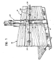
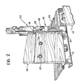
- a hollow pillar of strong sheet-metal box section is generally indicated 10.
- the pillar 10 is hinged removably at its base to a side member 12 of the floor of a commercial vehicle, such as a lorry, trailer or semi-trailer.
- the lower edges of two adjacent drop boards 14, between which the pillar 10 is interposed, are also hinged removably to the side member 12.
- the adjacent side edges of the boards 14 have respective lateral square bushes 16 in their upper parts.
- the bushes 16 are housed in corresponding lateral notches 18 in the pillar 10 and are held by respective bolts of which more will be said below. These bolts are operable by means of respective levers 20 which are accessible on the outer face of the pillar 10.
- a removable upper upright 22 is associated with the pillar 10 for the lateral support of a rib (not shown) for the tarpaulin for covering the body.
- the boards 14 are provided with fixed eyelets 24 for the passage, in known manner, of a sealing cable 26.
- Each upright, such as 10, is also provided with an eyelet 28 which also holds the sealing cable 26.
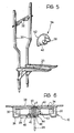
- the eyelet 28 forms part of a rotating locking assembly which will now be described with reference to Figures 4 to 7.
- FIGS 4 and 5 show the two bolts 30 which are movable longitudinally and parallel to each other within the pillar 10.
- Each of these bolts 30 is provided in its upper part with an abutment in the form of a strong finger 32 projecting towards the other bolt.
- the eyelet of the pillar 10 is again indicated 28.
- This eyelet 28 forms part of a rotating assembly, indicated 34, which can better be seen in Figure 6.
- the assembly 34 includes a central tubular shaft 40 to which is welded a sector-shaped plate 42 which faces the wall 38 and acts as a member for locking the bolts 30.
- the tubular shaft 40 is supported rotatably in a bush 43 which is welded to the wall 36 so that the assembly 34 rotates about an axis A normal to the two walls 36 and 38 and situated in a position intermediate the two bolts 30.
- the end of the shaft 40 opposite the plate 42 projects through a hole 44 formed in the centre of a recess 46 formed in the wall 36.
- the eyelet 28 is constituted by a piece of round bar shaped into a "flag" shape.
- the eyelet 28 includes a pin 48 which corresponds to the pole of the "flag" and extends transversely through the cavity in the shaft 40.
- the eyelet 28 may be rotated between a projecting position for receiving the sealing cable 26 and a position in which it is brought down against the wall 36 in the recess 46 so as not to constitute an undesirable projection when it is not in use.
- the eyelet 28 When the eyelet 28 is projecting and the cable 26 does not pass through it, it may be used as a key for rotating the assembly 34.
- the cavity of the shaft 40 contains a helical compression spring 50 which acts at one end against the wall 38 and at the other against the pin 48 of the eyelet 28.
- the sector-shaped plate 42 is kept pressed against the corresponding front face of the bush 43 by virtue of the spring 50, causing friction with respect to the rotation of the assembly 34. The latter cannot therefore rotate accidentally.
- the spring 50 also causes friction with respect to the pin 48. This serves particularly to prevent the eyelet 28 from accidentally leaving its depressed position in the recess 46.
- the plate 42 is in the form of a sector with a circumferential edge 52 which extends substantially through 180°.
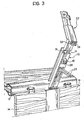
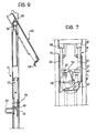
- the rotating element 42 ensures not only the secure locking of the pillar 10 and the boards 14 but also that of the upright 22 in its position of alignment with the pillar 10. This capability is illustrated in Figures 8 and 9.
- the pillar 10 is provided at its upper end with a fixed tubular pin 54.
- the upright 22, which is channel sectioned, has an internal curved plate 56 hooked onto the pin 54.
- the lower end of the upright 22 is provided with a pair of tabs 58 which are both visible in Figure 3.
- Each of these tabs 58 is formed by a right-angled, "Z"-shaped element welded in correspondence with one of the notches 18 for housing the lateral bushes 16.
- the upright 22 is refitted onto its pillar 10 by reversal of this operation.
Landscapes
- Engineering & Computer Science (AREA)
- Chemical & Material Sciences (AREA)
- Combustion & Propulsion (AREA)
- Transportation (AREA)
- Mechanical Engineering (AREA)
- Body Structure For Vehicles (AREA)
- Seal Device For Vehicle (AREA)
- Lock And Its Accessories (AREA)
- Forklifts And Lifting Vehicles (AREA)
Priority Applications (1)
| Application Number | Priority Date | Filing Date | Title |
|---|---|---|---|
| AT88830497T ATE79595T1 (de) | 1988-05-16 | 1988-11-22 | Vorrichtung zum absperren der verschlusselemente eines nutzfahrzeugaufbaus. |
Applications Claiming Priority (2)
| Application Number | Priority Date | Filing Date | Title |
|---|---|---|---|
| IT8853155U IT214599Z2 (it) | 1988-05-16 | 1988-05-16 | Dispositivo per la piombatura degli elementi di recinzione di un cassone di veicolo industriale |
| IT5315588U | 1988-05-16 |
Publications (3)
| Publication Number | Publication Date |
|---|---|
| EP0342304A2 true EP0342304A2 (de) | 1989-11-23 |
| EP0342304A3 EP0342304A3 (en) | 1990-03-14 |
| EP0342304B1 EP0342304B1 (de) | 1992-08-19 |
Family
ID=11280418
Family Applications (1)
| Application Number | Title | Priority Date | Filing Date |
|---|---|---|---|
| EP88830497A Expired - Lifetime EP0342304B1 (de) | 1988-05-16 | 1988-11-22 | Vorrichtung zum Absperren der Verschlusselemente eines Nutzfahrzeugaufbaus |
Country Status (4)
| Country | Link |
|---|---|
| EP (1) | EP0342304B1 (de) |
| AT (1) | ATE79595T1 (de) |
| DE (1) | DE3873910T2 (de) |
| IT (1) | IT214599Z2 (de) |
Family Cites Families (4)
| Publication number | Priority date | Publication date | Assignee | Title |
|---|---|---|---|---|
| DE8029162U1 (de) * | 1980-11-03 | 1981-03-19 | Rosén, Göran, 6350 Bad Nauheim | Runge für Ladeplattformen |
| SE8304867D0 (sv) * | 1983-09-12 | 1983-09-12 | Kinnegrip Ab | Lostagbar vertikal stolpe till lastflak med av denna uppburen stotta till kapell och liknande |
| SE453067B (sv) * | 1986-09-03 | 1988-01-11 | Erik Gosta Petersson | Feste for losbar fastsettning av en lemstolpe for en overbyggnad pa ett lastfordon |
| IT208117Z2 (it) * | 1986-10-01 | 1988-04-11 | Viberti Off Spa | Dispositivo per il bloccaggio di sponde ribaltabili di cassoni di veicoli industriali |
-
1988
- 1988-05-16 IT IT8853155U patent/IT214599Z2/it active
- 1988-11-22 EP EP88830497A patent/EP0342304B1/de not_active Expired - Lifetime
- 1988-11-22 DE DE8888830497T patent/DE3873910T2/de not_active Expired - Fee Related
- 1988-11-22 AT AT88830497T patent/ATE79595T1/de not_active IP Right Cessation
Also Published As
| Publication number | Publication date |
|---|---|
| IT8853155V0 (it) | 1988-05-16 |
| DE3873910D1 (en) | 1992-09-24 |
| DE3873910T2 (de) | 1993-03-18 |
| EP0342304A3 (en) | 1990-03-14 |
| EP0342304B1 (de) | 1992-08-19 |
| ATE79595T1 (de) | 1992-09-15 |
| IT214599Z2 (it) | 1990-05-09 |
Similar Documents
| Publication | Publication Date | Title |
|---|---|---|
| US5685594A (en) | Two-way tailgate for a vehicle | |
| EP1186480B1 (de) | Schutzvorrichtung zur Sicherung eines Laderaumes in einem Fahrzeuginnenraum | |
| DE4010276C2 (de) | ||
| US6129401A (en) | Vehicle storage bin | |
| DE4438910C1 (de) | Rückhaltevorrichtung für den Laderaum von Kraftfahrzeugen, wie z. B. für Kombinationskraftwagen oder Großraum-Personenkraftwagen | |
| US5873633A (en) | Retardation lock member for motor vehicle seat component | |
| US4884729A (en) | Spare tire rack | |
| EP0474368A1 (de) | Fahrzeug und geteilte Klapprückenlehne für einen Fahrzeugsitz | |
| CA2360607C (en) | Storage tray for use with a tonneau cover assembly | |
| NL8203128A (nl) | Inrichting ter bevestiging van een afneembaar samenstellend deel aan het freem van een tweewielig motorvoertuig. | |
| DE69902849T2 (de) | Vorrichtung zur Ermöglichung des Durchlasses zwischen Sitz- u. Kofferraum eines Kraftfahrzeuges | |
| EP0342304B1 (de) | Vorrichtung zum Absperren der Verschlusselemente eines Nutzfahrzeugaufbaus | |
| US4229131A (en) | Tiedown winch | |
| DE69808451T2 (de) | Gurtaufroller | |
| DE3841247A1 (de) | Vorrichtung zum verriegeln einer umlegbaren rueckenlehne eines fahrzeugsitzes | |
| EP1350675B1 (de) | Handschuhfach | |
| US4658613A (en) | Automobile anti-theft device | |
| EP0051575B1 (de) | Runge für Ladeplattformen | |
| DE69838580T2 (de) | Einziehbares unterteilungssystem für fahrzeuge | |
| US4488618A (en) | Body for motorscooter | |
| DE19651115C2 (de) | Verriegelungsvorrichtung für Fahrzeugklappsitze | |
| JP2532003Y2 (ja) | 車載用収納装置 | |
| JPH0420673Y2 (de) | ||
| JPS5821818Y2 (ja) | テイルトキャブのロック装置 | |
| KR200175407Y1 (ko) | 자동차용 도어의 인너핸들조립체(inner handle lock in a vehicle door) |
Legal Events
| Date | Code | Title | Description |
|---|---|---|---|
| PUAI | Public reference made under article 153(3) epc to a published international application that has entered the european phase |
Free format text: ORIGINAL CODE: 0009012 |
|
| AK | Designated contracting states |
Kind code of ref document: A2 Designated state(s): AT BE DE FR GB IT LU NL SE |
|
| PUAL | Search report despatched |
Free format text: ORIGINAL CODE: 0009013 |
|
| TCAT | At: translation of patent claims filed | ||
| EL | Fr: translation of claims filed | ||
| AK | Designated contracting states |
Kind code of ref document: A3 Designated state(s): AT BE DE FR GB IT LU NL SE |
|
| DET | De: translation of patent claims | ||
| 17P | Request for examination filed |
Effective date: 19900830 |
|
| RAP1 | Party data changed (applicant data changed or rights of an application transferred) |
Owner name: VIBERTI VEICOLI INDUSTRIALI S.R.L. |
|
| 17Q | First examination report despatched |
Effective date: 19911017 |
|
| GRAA | (expected) grant |
Free format text: ORIGINAL CODE: 0009210 |
|
| AK | Designated contracting states |
Kind code of ref document: B1 Designated state(s): AT BE DE FR GB IT LU NL SE |
|
| REF | Corresponds to: |
Ref document number: 79595 Country of ref document: AT Date of ref document: 19920915 Kind code of ref document: T |
|
| ITF | It: translation for a ep patent filed | ||
| REF | Corresponds to: |
Ref document number: 3873910 Country of ref document: DE Date of ref document: 19920924 |
|
| ET | Fr: translation filed | ||
| PLBE | No opposition filed within time limit |
Free format text: ORIGINAL CODE: 0009261 |
|
| STAA | Information on the status of an ep patent application or granted ep patent |
Free format text: STATUS: NO OPPOSITION FILED WITHIN TIME LIMIT |
|
| 26N | No opposition filed | ||
| EPTA | Lu: last paid annual fee | ||
| PGFP | Annual fee paid to national office [announced via postgrant information from national office to epo] |
Ref country code: NL Payment date: 19941130 Year of fee payment: 7 |
|
| EAL | Se: european patent in force in sweden |
Ref document number: 88830497.9 |
|
| PGFP | Annual fee paid to national office [announced via postgrant information from national office to epo] |
Ref country code: LU Payment date: 19950501 Year of fee payment: 7 |
|
| PGFP | Annual fee paid to national office [announced via postgrant information from national office to epo] |
Ref country code: GB Payment date: 19950519 Year of fee payment: 7 |
|
| PGFP | Annual fee paid to national office [announced via postgrant information from national office to epo] |
Ref country code: SE Payment date: 19950522 Year of fee payment: 7 |
|
| PGFP | Annual fee paid to national office [announced via postgrant information from national office to epo] |
Ref country code: AT Payment date: 19950523 Year of fee payment: 7 |
|
| PGFP | Annual fee paid to national office [announced via postgrant information from national office to epo] |
Ref country code: FR Payment date: 19950530 Year of fee payment: 7 |
|
| PGFP | Annual fee paid to national office [announced via postgrant information from national office to epo] |
Ref country code: BE Payment date: 19950531 Year of fee payment: 7 |
|
| PGFP | Annual fee paid to national office [announced via postgrant information from national office to epo] |
Ref country code: DE Payment date: 19950719 Year of fee payment: 7 |
|
| PG25 | Lapsed in a contracting state [announced via postgrant information from national office to epo] |
Ref country code: LU Free format text: LAPSE BECAUSE OF NON-PAYMENT OF DUE FEES Effective date: 19951122 Ref country code: GB Effective date: 19951122 Ref country code: AT Effective date: 19951122 |
|
| PG25 | Lapsed in a contracting state [announced via postgrant information from national office to epo] |
Ref country code: SE Effective date: 19951123 |
|
| PG25 | Lapsed in a contracting state [announced via postgrant information from national office to epo] |
Ref country code: BE Effective date: 19951130 |
|
| BERE | Be: lapsed |
Owner name: VIBERTI VEICOLI INDUSTRIALI S.R.L. Effective date: 19951130 |
|
| PG25 | Lapsed in a contracting state [announced via postgrant information from national office to epo] |
Ref country code: NL Effective date: 19960601 |
|
| GBPC | Gb: european patent ceased through non-payment of renewal fee |
Effective date: 19951122 |
|
| PG25 | Lapsed in a contracting state [announced via postgrant information from national office to epo] |
Ref country code: FR Effective date: 19960731 |
|
| NLV4 | Nl: lapsed or anulled due to non-payment of the annual fee |
Effective date: 19960601 |
|
| PG25 | Lapsed in a contracting state [announced via postgrant information from national office to epo] |
Ref country code: DE Effective date: 19960801 |
|
| EUG | Se: european patent has lapsed |
Ref document number: 88830497.9 |
|
| REG | Reference to a national code |
Ref country code: FR Ref legal event code: ST |
|
| PG25 | Lapsed in a contracting state [announced via postgrant information from national office to epo] |
Ref country code: IT Free format text: LAPSE BECAUSE OF NON-PAYMENT OF DUE FEES Effective date: 20051122 |