EP0341835B1 - Verfahren zum Entfernen von Oxiden aus metallischem Pulver - Google Patents
Verfahren zum Entfernen von Oxiden aus metallischem Pulver Download PDFInfo
- Publication number
- EP0341835B1 EP0341835B1 EP89303674A EP89303674A EP0341835B1 EP 0341835 B1 EP0341835 B1 EP 0341835B1 EP 89303674 A EP89303674 A EP 89303674A EP 89303674 A EP89303674 A EP 89303674A EP 0341835 B1 EP0341835 B1 EP 0341835B1
- Authority
- EP
- European Patent Office
- Prior art keywords
- plasma
- plasma stream
- metal particles
- stream
- substrate
- Prior art date
- Legal status (The legal status is an assumption and is not a legal conclusion. Google has not performed a legal analysis and makes no representation as to the accuracy of the status listed.)
- Expired - Lifetime
Links
- 238000000034 method Methods 0.000 title claims description 30
- 239000000843 powder Substances 0.000 title description 29
- 239000000758 substrate Substances 0.000 claims description 53
- 238000000576 coating method Methods 0.000 claims description 52
- 239000011248 coating agent Substances 0.000 claims description 36
- 238000012546 transfer Methods 0.000 claims description 36
- 239000002923 metal particle Substances 0.000 claims description 22
- RTAQQCXQSZGOHL-UHFFFAOYSA-N Titanium Chemical compound [Ti] RTAQQCXQSZGOHL-UHFFFAOYSA-N 0.000 claims description 18
- 239000010936 titanium Substances 0.000 claims description 18
- 229910052719 titanium Inorganic materials 0.000 claims description 18
- 230000003068 static effect Effects 0.000 claims description 8
- 230000008878 coupling Effects 0.000 claims description 6
- 238000010168 coupling process Methods 0.000 claims description 6
- 238000005859 coupling reaction Methods 0.000 claims description 6
- 229910052782 aluminium Inorganic materials 0.000 claims description 4
- XAGFODPZIPBFFR-UHFFFAOYSA-N aluminium Chemical compound [Al] XAGFODPZIPBFFR-UHFFFAOYSA-N 0.000 claims description 4
- 229910052715 tantalum Inorganic materials 0.000 claims description 4
- GUVRBAGPIYLISA-UHFFFAOYSA-N tantalum atom Chemical compound [Ta] GUVRBAGPIYLISA-UHFFFAOYSA-N 0.000 claims description 4
- 239000012255 powdered metal Substances 0.000 claims description 3
- 239000002245 particle Substances 0.000 description 23
- 239000013528 metallic particle Substances 0.000 description 14
- 230000008569 process Effects 0.000 description 14
- 230000007246 mechanism Effects 0.000 description 9
- 230000003647 oxidation Effects 0.000 description 7
- 238000007254 oxidation reaction Methods 0.000 description 7
- 239000007789 gas Substances 0.000 description 6
- 238000005507 spraying Methods 0.000 description 5
- XKRFYHLGVUSROY-UHFFFAOYSA-N Argon Chemical compound [Ar] XKRFYHLGVUSROY-UHFFFAOYSA-N 0.000 description 4
- 238000004140 cleaning Methods 0.000 description 4
- 239000000463 material Substances 0.000 description 4
- 239000011261 inert gas Substances 0.000 description 3
- 229910052751 metal Inorganic materials 0.000 description 3
- 239000002184 metal Substances 0.000 description 3
- 239000007921 spray Substances 0.000 description 3
- 229910052786 argon Inorganic materials 0.000 description 2
- 230000015572 biosynthetic process Effects 0.000 description 2
- 230000009467 reduction Effects 0.000 description 2
- 239000011819 refractory material Substances 0.000 description 2
- 239000011800 void material Substances 0.000 description 2
- 230000009471 action Effects 0.000 description 1
- 239000000853 adhesive Substances 0.000 description 1
- 230000001070 adhesive effect Effects 0.000 description 1
- 238000013459 approach Methods 0.000 description 1
- 238000006243 chemical reaction Methods 0.000 description 1
- 239000000498 cooling water Substances 0.000 description 1
- 238000000151 deposition Methods 0.000 description 1
- 238000010586 diagram Methods 0.000 description 1
- 239000000284 extract Substances 0.000 description 1
- 239000001307 helium Substances 0.000 description 1
- 229910052734 helium Inorganic materials 0.000 description 1
- SWQJXJOGLNCZEY-UHFFFAOYSA-N helium atom Chemical compound [He] SWQJXJOGLNCZEY-UHFFFAOYSA-N 0.000 description 1
- 239000001257 hydrogen Substances 0.000 description 1
- 229910052739 hydrogen Inorganic materials 0.000 description 1
- 125000004435 hydrogen atom Chemical class [H]* 0.000 description 1
- 238000002844 melting Methods 0.000 description 1
- 230000008018 melting Effects 0.000 description 1
- 150000002739 metals Chemical class 0.000 description 1
- 238000012986 modification Methods 0.000 description 1
- 230000004048 modification Effects 0.000 description 1
- 239000011236 particulate material Substances 0.000 description 1
- 238000007750 plasma spraying Methods 0.000 description 1
- 239000012254 powdered material Substances 0.000 description 1
- 238000012545 processing Methods 0.000 description 1
- 239000003870 refractory metal Substances 0.000 description 1
- 238000012163 sequencing technique Methods 0.000 description 1
- XLYOFNOQVPJJNP-UHFFFAOYSA-N water Substances O XLYOFNOQVPJJNP-UHFFFAOYSA-N 0.000 description 1
Images


Classifications
-
- C—CHEMISTRY; METALLURGY
- C23—COATING METALLIC MATERIAL; COATING MATERIAL WITH METALLIC MATERIAL; CHEMICAL SURFACE TREATMENT; DIFFUSION TREATMENT OF METALLIC MATERIAL; COATING BY VACUUM EVAPORATION, BY SPUTTERING, BY ION IMPLANTATION OR BY CHEMICAL VAPOUR DEPOSITION, IN GENERAL; INHIBITING CORROSION OF METALLIC MATERIAL OR INCRUSTATION IN GENERAL
- C23G—CLEANING OR DE-GREASING OF METALLIC MATERIAL BY CHEMICAL METHODS OTHER THAN ELECTROLYSIS
- C23G5/00—Cleaning or de-greasing metallic material by other methods; Apparatus for cleaning or de-greasing metallic material with organic solvents
-
- B—PERFORMING OPERATIONS; TRANSPORTING
- B22—CASTING; POWDER METALLURGY
- B22F—WORKING METALLIC POWDER; MANUFACTURE OF ARTICLES FROM METALLIC POWDER; MAKING METALLIC POWDER; APPARATUS OR DEVICES SPECIALLY ADAPTED FOR METALLIC POWDER
- B22F1/00—Metallic powder; Treatment of metallic powder, e.g. to facilitate working or to improve properties
- B22F1/14—Treatment of metallic powder
- B22F1/145—Chemical treatment, e.g. passivation or decarburisation
-
- C—CHEMISTRY; METALLURGY
- C23—COATING METALLIC MATERIAL; COATING MATERIAL WITH METALLIC MATERIAL; CHEMICAL SURFACE TREATMENT; DIFFUSION TREATMENT OF METALLIC MATERIAL; COATING BY VACUUM EVAPORATION, BY SPUTTERING, BY ION IMPLANTATION OR BY CHEMICAL VAPOUR DEPOSITION, IN GENERAL; INHIBITING CORROSION OF METALLIC MATERIAL OR INCRUSTATION IN GENERAL
- C23C—COATING METALLIC MATERIAL; COATING MATERIAL WITH METALLIC MATERIAL; SURFACE TREATMENT OF METALLIC MATERIAL BY DIFFUSION INTO THE SURFACE, BY CHEMICAL CONVERSION OR SUBSTITUTION; COATING BY VACUUM EVAPORATION, BY SPUTTERING, BY ION IMPLANTATION OR BY CHEMICAL VAPOUR DEPOSITION, IN GENERAL
- C23C4/00—Coating by spraying the coating material in the molten state, e.g. by flame, plasma or electric discharge
- C23C4/12—Coating by spraying the coating material in the molten state, e.g. by flame, plasma or electric discharge characterised by the method of spraying
- C23C4/134—Plasma spraying
Definitions
- the present invention relates to plasma systems in which metal particles are sprayed by a plasma stream, and more particularly to a method of removing oxides from metallic powder particles introduced into a plasma stream.
- Refractory materials such as titanium and tantalum and even aluminum are difficult to produce in powdered form without an oxide layer being present on the surface of the powder particles.
- a typical process of forming the powder involves melting the metal and then introducing the molten metal into a gas stream. As the powder particles are formed, the highly oxidizable nature of the material causes an oxide layer to form on the outside of the particles. Such oxidation can be minimized by using other processes to form the powder, but such processes tend to be relatively expensive.
- U.S. Patent 4,328,257 issued on May 4, 1982.
- This patent describes a plasma system in which a vacuum source creates a low static pressure within an enclosure containing a plasma gun and a workpiece located downstream of the plasma gun.
- the plasma gun ionizes an inert gas to produce a plasma stream.
- the plasma stream flows from the plasma gun to the workpiece at supersonic speeds in the presence of the low static pressure provided by the vacuum source.
- Metallic powder introduced into the plasma stream at a location adjacent the plasma gun is carried to the workpiece where it is deposited on the workpiece as a coating.
- the plasma system described in the US 4,328,257 Patent employs switchable transfer arc power supplies which are advantageously employed to initially establish a negative or cathodic condition at the workpiece for purposes of cleaning the workpiece. Thereafter, the workpiece is made positive relative to the plasma gun to enhance the depositing of the metallic powders introduced into the plasma stream onto the workpiece.
- the workpiece is made positive relative to the plasma gun to enhance the depositing of the metallic powders introduced into the plasma stream onto the workpiece.
- some oxidation of the metallic powder still occurs as it travels along the plasma stream. This is especially true in the case of the highly oxidizable refractory materials, even when such materials are introduced into the plasma stream in a relatively pure, oxide-free form.
- JP-A-56055562 An alternative plasma spraying method is provided by JP-A-56055562.
- the apparatus described operates without a vacuum or low pressure source.
- a continuous negative voltage is applied to the substrate during spraying. This removes any oxide film on the substrate and maintains a clean surface, thus encouraging the formation of a coating with superior adhesive strength.
- Oxide coatings are removed from metal particles in powdered form utilizing methods in accordance with the invention in which the particles are introduced into a plasma stream in the presence of a continuous negative transfer arc.
- the plasma stream is produced by ionizing an inert gas within a plasma gun.
- the plasma stream is provided with supersonic speed through the use of a vacuum source to provide a low static pressure.
- the continuous negative transfer arc is produced by continuously coupling a negative transfer arc power source between the plasma gun and a cathode located downstream from the plasma gun.
- the continuous presence or the negative transfer arc along a portion of the plasma stream between the plasma gun and the cathode produces an electron emission from the cathode.
- the electron emission produces an electromagnetic propagation of electron current.
- the electromagnetic propagation has been found to remove substantial portions of oxide coatings already formed on metallic particles traveling in the plasma stream between the plasma gun and the cathode, and to prevent such oxide layers from forming in instances where the metallic particles are introduced into the plasma stream in a relatively pure, oxide-free form.
- a continuous cleaning, oxide-removing process takes place at the cathode, which acts to continuously clean the metallic coating formed therein where the cathode comprises a substrate.
- the continuous negative transfer arc can be employed to simply clean the metal particles by removing the oxide coatings therefrom, in which event the cleaned metal particles in the plasma stream are collected in a receptacle located downstream from the cathode.
- the cathode may comprise a hollow, generally ring-shaped electrode disposed within the plasma stream so that the plasma stream flows through the hollow interior thereof.
- the continuous negative transfer arc can be used to remove the oxide coatings from the metal particles prior to the particles forming a coating on a substrate or other workpiece. This is accomplished by coupling the substrate as the cathode. Following removal of the oxide coatings, the cleaned particles arrive at the substrate where they form a relatively oxide-free coating on the substrate.
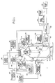
- Fig. 1 depicts a plasma system for use in carrying out methods according to the invention.
- the plasma system of Fig. 1 includes a plasma chamber 10 that provides a sealed vacuum-maintaining and pressure-resistant insulative enclosure.
- the chamber 10 is defined by a cylindrical principal body portion 12, and an upper lid portion 13 joined thereto.
- the body portion 12 of the plasma chamber 10 includes a bottom collector cone 14 that leads into and communicates with associated units for processing the exiting gases and particulates in maintaining the desired ambient pressure.
- a downwardly directed plasma stream is established by a plasma gun 16 mounted within the interior of the chamber lid 13, the position of which gun 16 is controlled by a plasma gun motion mechanism 18.
- Both parts of the plasma chamber 10 are advantageously constructed as double-walled, water-cooled enclosures and the lid 13 is removable for access to the operative parts.
- the gun motion mechanism 18 supports and controls the plasma gun 16 through sealed bearing and couplings in the walls of the chamber lid 13.
- a powder feed mechanism 20 also coupled to the chamber lid 13 provides controlled feed of a heated powder into the plasma stream through flexible tubes that are coupled to the plasma gun 16.
- the powder feed mechanism 20 is employed to introduce into the plasma stream metallic powder which is to be cleaned of oxide coating thereon or which is to be maintained relatively oxide-free in accordance with the invention.
- the downwardly directed plasma stream impinges on a workpiece 24 which is supported on an internally cooled conductive workpiece holder 25 and which is positioned and moved while in operation via a shaft extending through the chamber body 12 to an exterior workpiece motion mechanism 26.
- Both the workpiece holder 25 and dummy sting 28 are adjustable as to insert position with respect to the central axis of the chamber 10 and electrically conductive so that they may be held at selected potential levels for transfer arc generation during various phases of operation.
- the collector cone 14 directs the overspray gaseous and particulate materials into a baffle/filter module 32 having a water-cooled baffle section thereof for initially coupling the overspray and an in-line filter section thereof for extracting the majority of the entrained particle matter. Effluent passing through the baffle/filter module 32 is then directed through a heat-exchanger module 36, which may be another water-cooled unit, into a vacuum manifold 38 containing an overspray filter/collector unit 40 which extracts substantially all particulate remaining in the flow.
- the vacuum manifold 38 communicates with vacuum pumps 42 having sufficient capacity to maintain a desired ambient pressure within the chamber 10. This ambient pressure which is typically in the range from 60.8 KPa (0.6 atmospheres) down to 0.1 KPa (0.001 atmospheres) produces a static pressure sufficient to provide the plasma stream with supersonic speed.
- the baffle/filter module 32 and the heat-exchanger module 36, as well as the overspray filter/collector 40 are preferably double-walled water-cooled systems, and any of the types well known and widely used in plasma systems may be employed.
- the entire system may be mounted on rollers and movable along rails for ease of handling and servicing of different parts of the system. Conventional viewing windows, water-cooled access doors and insulated feedthrough plates for electrical connection have not been shown or discussed in detail, for simplicity of illustration.
- the workpiece support and motion control system is advantageously mounted in a hinged front access door 43 in the chamber body 12.
- Flexible water-cooled cables couple a plasma power source 46, a high frequency power supply 48 and a negative transfer arc power source via the bus bars 44 into the plasma gun 16 for generation of the plasma stream.
- the plasma power source 46 provides the requisite electrical potential difference between the electrodes of the plasma gun 16.
- the high frequency power supply 48 is used to initiate an arc within the plasma gun 16 by superimposing a high frequency voltage discharge on the D.C. power supply comprising the plasma power source 46.
- the negative transfer arc power source which is coupled between the plasma gun 16 and the workpiece 24 provides a continuous negative transfer arc therebetween in accordance with the invention.
- Operation of the plasma gun 16 entails usage of a water booster pump 52 to provide an adequate flow of cooling water through the interior of the plasma gun 16.
- a plasma gas source 54 provides a suitable ionizing gas for generation of the plasma stream.
- the plasma gas here employed is either argon along or argon seeded with helium or hydrogen, although other gases may be employed as is well known to those skilled in the art.
- Transfer arc control circuits 60 may be used to control the negative transfer arc power source 50.
- Fig. 1 Most of what has been shown and described in connection with Fig. 1 is similar to the plasma system described in previously referred to U.S. Patent 4,328,257 of Muehlberger et al., and reference thereto is made to the extent that further explanation of one or more portions of the plasma system may be needed.
- Fig. 2 is an idealized and simplified schematic view of a portion of the plasma system of Fig. 1 in which the workpiece 24 comprises a substrate 70.
- Fig. 2 depicts a plasma system for spraying metallic powder to form a coating on the substrate 70.
- the plasma gun 16 ionizes inert gas in the manner previously described to provide a plasma stream which extends between the plasma gun 16 and the substrate 70.
- the plasma stream is represented by a series of dashed lines 72.
- the negative transfer arc power source 50 is continuously coupled between the plasma gun 16 and the substrate 70.
- the negative transfer arc power source 50 has a positive terminal 74 which is coupled to the plasma gun 16.
- the negative transfer arc power source 50 has a negative terminal 76 which is coupled to the substrate 70. This causes the substrate 70 to act as a cathode. Accordingly, the negative transfer arc power supply 50 provides a continuous negative transfer arc in conjunction with the plasma stream 72 along a portion of the plasma stream 72 between the plasma gun 16 and the substrate 70.
- Metallic powder to be coated on the substrate 70 is provided by the powder feed mechanism 20 previously described in connection with Fig. 1.
- the powder feed mechanism 20 which is not shown in Fig. 2 includes a powder delivery tube 78 which terminates within the plasma gun 16 where the metallic powder is fed into the plasma stream 72.
- the substrate 70 which functions as a cathode relative to the plasma gun 16 by virtue of the negative transfer arc power source 50 emits electrons therefrom. This results in an electromagnetic propagation of electron current between the substrate 70 and the plasma gun 16.
- the flow of negative electrons from the substrate 70 encounters the particles and removes all or at least a substantial portion of any oxide coating present on the particles.
- the particles are substantially free of oxides.
- a continuous cleaning action is provided at the coating on the substrate 70, by virtue of which any oxides present at the coating continue to be removed therefrom.
- oxide coatings has been found to be particularly advantageous in the case of highly oxidizable refractory metals such as titanium, tantalum and even aluminum.
- the oxide coatings which are typically already present on such particles as a result of the powder forming process are removed from the particles as they travel to the substrate 70, resulting in a metallic coating on the substrate 70 which has a very low oxide content therein.
- Metallic particles introduced into the plasma stream 72 in a relatively pure, oxide-free form tend to remain so as they travel along the plasma stream 72 to the substrate 70.
- methods in accordance with the invention are advantageously used with metallic particles of all types including those which are highly oxidizable and those which oxidize at considerably lower rates.
- Fig. 4 is a photomicrograph, magnified 100 times, of a coating of titanium on a substrate such as the substrate 70 of Fig. 2.
- the titanium coating was placed on the substrate without using a negative transfer arc. It will be observed that the titanium coating has numerous dark spots therein, many of which are relatively large. The dark spots are voids and oxides in the coating.
- the coating in the example of Fig. 4 is regarded as being somewhat porous and having a rather high oxide content which is undesirable.
- Fig. 5 which is a photomicrograph, magnified 400 times, of a portion of the titanium coating and the substrate of Fig. 4 illustrates in even greater detail the significant voids and the substantial amount of oxides present in the titanium coating.
- Fig. 6 is a photomicrograph, magnified 100 times, of a titanium coating on a substrate.
- the titanium coating illustrated in Fig. 6 was applied using a continous negative transfer arc in the manner described in connection with Fig. 2. It will be observed that when compared with Fig. 4 the titanium coating of Fig. 6 has a substantially lower void and oxide content.
- the dark spots which represent voids and oxides are considerably fewer and smaller in size in Fig. 6.
- Fig. 7 is a photomicrograph, magnified 400 times, of a portion of the titanium coating and the substrate of Fig. 6.
- Fig. 7 illustrates in greater detail the low void and oxide content of the titanium coating applied in accordance with the invention, particularly when contrasted with the photomicrograph of similar magnification provided by Fig. 5.
- processes in accordance with the invention include the generation of a plasma stream such as the plasma stream 72 utilizing the plasma gun 16.
- the negative transfer arc power source 50 or other appropriate means is employed to continuously maintain a negative transfer arc in conjunction with the plasma stream 72 along a portion of the plasma stream 72.
- the negative transfer arc is maintained in conjunction with the plasma stream 72 along the entire length of the plasma stream 72 between the plasma gun 16 and the substrate 70.
- the plasma stream 72 may be employed in conjunction with the negative transfer arc to clean the surface of the substrate 70 where desired.
- the metal particles are entrained into and flow with the plasma stream 72 to the substrate 70, and in the process are cleansed of any oxide coatings thereon in the manner previously described.
- the metal particles are received by the substrate 70 where they form a coating thereon.
- the plasma stream 72 is provided with a supersonic speed. This is accomplished in the manner previously described in connection with Fig. 1 by use of the downstream vacuum pumps 42 to provide a relatively low static pressure in the region of the plasma gun 16 and the workpiece 24 or the substrate 70 within the plasma chamber 10.
- the metallic particles are coated on the surface of the substrate 70 in relatively oxide-free form, as well as being cleaned of oxide coatings in those instances where the particles are provided to the plasma stream 72 in an impure, oxide-coated form. It may be desirable in certain instances to clean the metallic particles by removing the oxide coatings therefrom without spraying the particles as a coating on a substrate. Such an arrangement for cleaning the metallic particles is shown in an idealized and simplified schematic form in Fig. 3.
- the arrangement of Fig. 3 is like that of Fig. 2, except that the cathode in the Fig. 3 arrangement is provided by a hollow, generally ring-shaped electrode 80.
- the electrode 80 which is coupled to the negative terminal 76 of the negative transfer arc power source 50 is disposed within the path of the plasma stream 72 so that the plasma stream 72 passes through the hollow interior thereof.
- the negative transfer arc power source 50 maintains a negative transfer arc along a portion of the plasma stream 72 extending from the plasma gun 16 to the electrode 80.
- the electrode 80 emits electrodes in the same manner as the substrate 70 in the arrangement of Fig. 2 to provide an electromagnetic propagation of electron current which removes oxide coatings from the metallic particles as the particles are conveyed by the plasma stream 72 from the plasma gun 16 to the electrode 80.
- the cleaned metallic particles are then collected by a receptacle 82 disposed within the path of the plasma stream 72 downstream of the electrode 80.
- the metallic powder which is introduced into the plasma stream 72 within the plasma gun 16 is thus cleansed of any oxide coatings thereon and then collected in a relatively pure form in the receptacle 82.
Landscapes
- Chemical & Material Sciences (AREA)
- Engineering & Computer Science (AREA)
- Chemical Kinetics & Catalysis (AREA)
- Metallurgy (AREA)
- Materials Engineering (AREA)
- Mechanical Engineering (AREA)
- General Chemical & Material Sciences (AREA)
- Organic Chemistry (AREA)
- Physics & Mathematics (AREA)
- Plasma & Fusion (AREA)
- Coating By Spraying Or Casting (AREA)
- Powder Metallurgy (AREA)
- Physical Or Chemical Processes And Apparatus (AREA)
- Physical Vapour Deposition (AREA)
Claims (9)
- Verfahren zum Befreien von Metallteilchen von Oxiden, umfassen die Schritte:
Betreiben einer Plasmakanone in Anwesenheit einer Quelle verringerten Drucks, um einen Überschall Plasmastrom zu erzeugen;
kontinuierliches Aufrechterhalten eines negativen Übergangsbogens in Verbindung mit dem Plasmastrom entlang eines Abschnitts des Plasmastroms;
Einführen von Metallteilchen in den Plasmastrom; und
Empfangen der Metallteilchen, nachdem diese entlang dem Abschnitt des Plasmastromes gelaufen sind. - Verfahren nach Anspruch 1, bei dem der Schritt des Aufnehmens der Metallteilchen aufweist:
Plazieren eines Substrats am Ende des Abschnitts des Plasmastromes, so daß die Metallteilchen eine Beschichtung auf dem Substrat bilden. - Verfahren nach Anspruch 1, bei dem der Schritt des Aufnehmens der Metallteilchen aufweist:
Plazieren eines Behälters stromab bezüglich des Abschnittes des Plasmastromes, um die Metallteilchen in dem Plasmastrom aufzufangen. - Verfahren nach Anspruch 2, bei dem der Schritt des Betreibens einer Plasmakanone aufweist:
Anbringen einer Plasmaquelle stromab bezüglich des Substrats von der Plasmakanone, um einen niedrigen statischen Druck zu schaffen, und Ionisieren eines Gasstromes in der Plasmakanone, um einen Plasmastrom zu erzeugen, der mit Überschallgeschwindigkeit zu dem Substrat hin im Beisein des niedrigen statischen Druckes fließt. - Verfahren nach irgendeinem vorhergehenden Anspruch, bei dem der Schritt des kontinuierlichen Aufrechterhaltens eines negativen Übergangsbogens aufweist:
dauerndes Koppeln einer Negativ-Übergangsbogen-Leistungsquelle zwischen der Plasmakanone und einer Stelle an einem Ende des Abschnitts gegenüber der Plasmakanone. - Verfahren nach irgendeinem der vorhergehenden Ansprüche, bei dem der Schritt des Einleitens von Metallteilchen aufweist:
Einleiten von Metallteilchen in den Plasmastrom im Inneren der Plasmakanone. - Verfahren nach irgendeinem der vorhergehenden Ansprüche, bei dem der Schritt des Einleitens der Metallteilchen in den Plasmastrom aufweist:
Einleiten pulverisierten Metalls, welches aus der Gruppe ausgewählt ist, die aus Titan, Tantal oder Aluminium besteht. - Verfahren nach Anspruch 1, bei dem der Schritt des Aufnehmens der Metallteilchen enthält:
den Schritt des Bereitstellens eines Gefäßes, der Schritt des Einleitens von Metallteilchen in den Plasmastrom den Schritt aufweist: Einleiten der oxidierten Metallteilchen in den Plasmastrom an einer Stelle benachbart der Plasmakanone, und der Schritt des kontinuierlichen Aufrechterhaltens eines negativen Übergangsbogens in Verbindung mit dem Plasmastrom entlang einem beschnitt des Plasmastroms die Schritte aufweist: Anbringen einer Elektrode im Inneren des Plasmastromes benachbart dem Behälter und kontinuierliches Ankoppeln einer Negativ-Übergangsbogen-Leistungsquelle zwischen der Plasmakanone und der Elektrode, um einen negativen Übergangsbogen zwischen der Plasmakanone und der Elektrode zu bilden. - Verfahren nach Anspruch 8, bei dem der Schritt des Anordnens einer Elektrode im Inneren des Plasmastromes aufweist:
das Anbringen einer ringförmigen Elektrode in der Nachbarschaft des Behälters derart, daß der Plasmastrom durch ein hohles Inneres der ringförmigen Elektrode hindurchtreten kann.
Applications Claiming Priority (2)
| Application Number | Priority Date | Filing Date | Title |
|---|---|---|---|
| US181400 | 1988-04-13 | ||
| US07/181,400 US4877640A (en) | 1988-04-13 | 1988-04-13 | Method of oxide removal from metallic powder |
Publications (2)
| Publication Number | Publication Date |
|---|---|
| EP0341835A1 EP0341835A1 (de) | 1989-11-15 |
| EP0341835B1 true EP0341835B1 (de) | 1993-02-10 |
Family
ID=22664120
Family Applications (1)
| Application Number | Title | Priority Date | Filing Date |
|---|---|---|---|
| EP89303674A Expired - Lifetime EP0341835B1 (de) | 1988-04-13 | 1989-04-13 | Verfahren zum Entfernen von Oxiden aus metallischem Pulver |
Country Status (5)
| Country | Link |
|---|---|
| US (1) | US4877640A (de) |
| EP (1) | EP0341835B1 (de) |
| JP (1) | JPH0660321B2 (de) |
| CA (1) | CA1337486C (de) |
| DE (1) | DE68904804T2 (de) |
Families Citing this family (10)
| Publication number | Priority date | Publication date | Assignee | Title |
|---|---|---|---|---|
| US5176938A (en) * | 1988-11-23 | 1993-01-05 | Plasmacarb Inc. | Process for surface treatment of pulverulent material |
| US5254237A (en) * | 1991-03-01 | 1993-10-19 | Snaper Alvin A | Plasma arc apparatus for producing diamond semiconductor devices |
| US5439498A (en) * | 1992-11-10 | 1995-08-08 | Exide Corporation | Process and system for the on-site remediation of lead-contaminated soil and waste battery casings |
| US5284503A (en) * | 1992-11-10 | 1994-02-08 | Exide Corporation | Process for remediation of lead-contaminated soil and waste battery |
| AU7075696A (en) * | 1995-09-19 | 1997-04-09 | Exide Corporation | Process for the destruction of chemical agents and munitions |
| US5681486A (en) * | 1996-02-23 | 1997-10-28 | The Boeing Company | Plasma descaling of titanium and titanium alloys |
| US5942023A (en) * | 1997-02-12 | 1999-08-24 | Exide Corporation | Process for recovering metals from electric arc furnace (EAF) dust |
| US6043451A (en) * | 1997-11-06 | 2000-03-28 | Promet Technologies, Inc. | Plasma spraying of nickel-titanium compound |
| US6915964B2 (en) * | 2001-04-24 | 2005-07-12 | Innovative Technology, Inc. | System and process for solid-state deposition and consolidation of high velocity powder particles using thermal plastic deformation |
| US7691177B2 (en) * | 2006-10-30 | 2010-04-06 | Niotan, Inc. | Method and an apparatus of plasma processing of tantalum particles |
Family Cites Families (9)
| Publication number | Priority date | Publication date | Assignee | Title |
|---|---|---|---|---|
| GB740368A (en) * | 1951-11-22 | 1955-11-09 | Martin Von Schulthess | A method for the spraying of metals |
| SE320250B (de) * | 1965-09-01 | 1970-02-02 | Libbey Owens Ford Glass Co | |
| US3429691A (en) * | 1966-08-19 | 1969-02-25 | Aerojet General Co | Plasma reduction of titanium dioxide |
| US3839618A (en) * | 1972-01-03 | 1974-10-01 | Geotel Inc | Method and apparatus for effecting high-energy dynamic coating of substrates |
| US3989511A (en) * | 1975-03-10 | 1976-11-02 | Westinghouse Electric Corporation | Metal powder production by direct reduction in an arc heater |
| US4328257A (en) * | 1979-11-26 | 1982-05-04 | Electro-Plasma, Inc. | System and method for plasma coating |
| US4642440A (en) * | 1984-11-13 | 1987-02-10 | Schnackel Jay F | Semi-transferred arc in a liquid stabilized plasma generator and method for utilizing the same |
| DE3538390A1 (de) * | 1985-10-29 | 1987-04-30 | Deutsche Forsch Luft Raumfahrt | Beschichtung fuer ein substrat und verfahren zu dessen herstellung |
| US4784159A (en) * | 1986-08-19 | 1988-11-15 | Cordis Corporation | Process for making an implantable device having plasma sprayed metallic porous surface |
-
1988
- 1988-04-13 US US07/181,400 patent/US4877640A/en not_active Expired - Lifetime
-
1989
- 1989-04-12 CA CA000596423A patent/CA1337486C/en not_active Expired - Fee Related
- 1989-04-13 DE DE8989303674T patent/DE68904804T2/de not_active Expired - Lifetime
- 1989-04-13 EP EP89303674A patent/EP0341835B1/de not_active Expired - Lifetime
- 1989-04-13 JP JP1094286A patent/JPH0660321B2/ja not_active Expired - Lifetime
Also Published As
| Publication number | Publication date |
|---|---|
| CA1337486C (en) | 1995-10-31 |
| JPH0660321B2 (ja) | 1994-08-10 |
| DE68904804D1 (de) | 1993-03-25 |
| DE68904804T2 (de) | 1993-05-27 |
| US4877640A (en) | 1989-10-31 |
| JPH0250901A (ja) | 1990-02-20 |
| EP0341835A1 (de) | 1989-11-15 |
Similar Documents
| Publication | Publication Date | Title |
|---|---|---|
| US4328257A (en) | System and method for plasma coating | |
| EP0341835B1 (de) | Verfahren zum Entfernen von Oxiden aus metallischem Pulver | |
| EP0241110B1 (de) | Reduktion von Oxiden in einer Plasmaumgebung beim Beschichten | |
| US4853250A (en) | Process of depositing particulate material on a substrate | |
| US3654108A (en) | Method for glow cleaning | |
| US5562841A (en) | Methods and apparatus for treating a work surface | |
| US20120261391A1 (en) | Atmospheric pressure plasma method for producing surface-modified particles and coatings | |
| JPH04254570A (ja) | 低周波数無線周波数プラズマ溶射 | |
| US8465809B2 (en) | Multiarc discharge moving bed reactor system | |
| EP0378673A4 (en) | Method and apparatus for atomization and spraying of molten metals | |
| AU2003224204A1 (en) | Method for the plasma cleaning of the surface of a material coated with an organic substance and the installation for carrying out said method | |
| CN105349955B (zh) | 用在磁控溅射设备中的一体化阳极和活性反应气体源装置 | |
| US20160288211A1 (en) | Multi-metal particle generator and method | |
| JP3933346B2 (ja) | イオンプレーティングを用いる成膜体の製造方法及び製造装置 | |
| CN1223241C (zh) | 常压射频冷等离子体系统及其喷枪 | |
| EP0468110B1 (de) | Elektrische Lichtbogenbehandlung von Teilchen | |
| JPH01152627A (ja) | プラズマ処理装置 | |
| RU2167743C2 (ru) | Устройство для получения ультрадисперсных порошков | |
| JP3336541B2 (ja) | ガス・デポジション法でのガス循環法およびガス・デポジション装置用のガス循環装置 | |
| JPH0775689B2 (ja) | 熱プラズマジェット発生装置 | |
| EP3766609A1 (de) | Verfahren und vorrichtung zum spülen eines produktionsraums für die metallpulverherstellung | |
| JPH0722696B2 (ja) | 微粉末の製造方法と装置ならびにその利用方法 | |
| JPH0225986B2 (de) | ||
| Muehlberger et al. | Method of Oxide Removal From Metallic Powder | |
| JPH03104828A (ja) | 高温溶融物の汚染を低減させる方法 |
Legal Events
| Date | Code | Title | Description |
|---|---|---|---|
| PUAI | Public reference made under article 153(3) epc to a published international application that has entered the european phase |
Free format text: ORIGINAL CODE: 0009012 |
|
| AK | Designated contracting states |
Kind code of ref document: A1 Designated state(s): CH DE FR GB IT LI NL SE |
|
| 17P | Request for examination filed |
Effective date: 19900316 |
|
| 17Q | First examination report despatched |
Effective date: 19910517 |
|
| ITF | It: translation for a ep patent filed | ||
| GRAA | (expected) grant |
Free format text: ORIGINAL CODE: 0009210 |
|
| AK | Designated contracting states |
Kind code of ref document: B1 Designated state(s): CH DE FR GB IT LI NL SE |
|
| REF | Corresponds to: |
Ref document number: 68904804 Country of ref document: DE Date of ref document: 19930325 |
|
| ET | Fr: translation filed | ||
| PLBE | No opposition filed within time limit |
Free format text: ORIGINAL CODE: 0009261 |
|
| STAA | Information on the status of an ep patent application or granted ep patent |
Free format text: STATUS: NO OPPOSITION FILED WITHIN TIME LIMIT |
|
| 26N | No opposition filed | ||
| EAL | Se: european patent in force in sweden |
Ref document number: 89303674.9 |
|
| REG | Reference to a national code |
Ref country code: CH Ref legal event code: PUE Owner name: ELECTRO-PLASMA, INC. TRANSFER- SULZER METCO AG |
|
| REG | Reference to a national code |
Ref country code: GB Ref legal event code: 732E |
|
| NLS | Nl: assignments of ep-patents |
Owner name: SULZER METCO AG |
|
| REG | Reference to a national code |
Ref country code: FR Ref legal event code: TP |
|
| REG | Reference to a national code |
Ref country code: FR Ref legal event code: CD |
|
| PGFP | Annual fee paid to national office [announced via postgrant information from national office to epo] |
Ref country code: SE Payment date: 20000320 Year of fee payment: 12 Ref country code: NL Payment date: 20000320 Year of fee payment: 12 |
|
| PG25 | Lapsed in a contracting state [announced via postgrant information from national office to epo] |
Ref country code: SE Free format text: LAPSE BECAUSE OF NON-PAYMENT OF DUE FEES Effective date: 20010414 |
|
| PG25 | Lapsed in a contracting state [announced via postgrant information from national office to epo] |
Ref country code: NL Free format text: LAPSE BECAUSE OF NON-PAYMENT OF DUE FEES Effective date: 20011101 |
|
| EUG | Se: european patent has lapsed |
Ref document number: 89303674.9 |
|
| REG | Reference to a national code |
Ref country code: GB Ref legal event code: IF02 |
|
| NLV4 | Nl: lapsed or anulled due to non-payment of the annual fee |
Effective date: 20011101 |
|
| PG25 | Lapsed in a contracting state [announced via postgrant information from national office to epo] |
Ref country code: IT Free format text: LAPSE BECAUSE OF NON-PAYMENT OF DUE FEES;WARNING: LAPSES OF ITALIAN PATENTS WITH EFFECTIVE DATE BEFORE 2007 MAY HAVE OCCURRED AT ANY TIME BEFORE 2007. THE CORRECT EFFECTIVE DATE MAY BE DIFFERENT FROM THE ONE RECORDED. Effective date: 20050413 |
|
| PGFP | Annual fee paid to national office [announced via postgrant information from national office to epo] |
Ref country code: CH Payment date: 20080415 Year of fee payment: 20 Ref country code: DE Payment date: 20080418 Year of fee payment: 20 |
|
| PGFP | Annual fee paid to national office [announced via postgrant information from national office to epo] |
Ref country code: FR Payment date: 20080412 Year of fee payment: 20 |
|
| PGFP | Annual fee paid to national office [announced via postgrant information from national office to epo] |
Ref country code: GB Payment date: 20080421 Year of fee payment: 20 |
|
| REG | Reference to a national code |
Ref country code: CH Ref legal event code: PL |
|
| REG | Reference to a national code |
Ref country code: GB Ref legal event code: PE20 Expiry date: 20090412 |
|
| PG25 | Lapsed in a contracting state [announced via postgrant information from national office to epo] |
Ref country code: GB Free format text: LAPSE BECAUSE OF EXPIRATION OF PROTECTION Effective date: 20090412 |