EP0341835B1 - Method of oxide removal from metallic powder - Google Patents
Method of oxide removal from metallic powder Download PDFInfo
- Publication number
- EP0341835B1 EP0341835B1 EP89303674A EP89303674A EP0341835B1 EP 0341835 B1 EP0341835 B1 EP 0341835B1 EP 89303674 A EP89303674 A EP 89303674A EP 89303674 A EP89303674 A EP 89303674A EP 0341835 B1 EP0341835 B1 EP 0341835B1
- Authority
- EP
- European Patent Office
- Prior art keywords
- plasma
- plasma stream
- metal particles
- stream
- substrate
- Prior art date
- Legal status (The legal status is an assumption and is not a legal conclusion. Google has not performed a legal analysis and makes no representation as to the accuracy of the status listed.)
- Expired - Lifetime
Links
Images


Classifications
-
- C—CHEMISTRY; METALLURGY
- C23—COATING METALLIC MATERIAL; COATING MATERIAL WITH METALLIC MATERIAL; CHEMICAL SURFACE TREATMENT; DIFFUSION TREATMENT OF METALLIC MATERIAL; COATING BY VACUUM EVAPORATION, BY SPUTTERING, BY ION IMPLANTATION OR BY CHEMICAL VAPOUR DEPOSITION, IN GENERAL; INHIBITING CORROSION OF METALLIC MATERIAL OR INCRUSTATION IN GENERAL
- C23G—CLEANING OR DE-GREASING OF METALLIC MATERIAL BY CHEMICAL METHODS OTHER THAN ELECTROLYSIS
- C23G5/00—Cleaning or de-greasing metallic material by other methods; Apparatus for cleaning or de-greasing metallic material with organic solvents
-
- B—PERFORMING OPERATIONS; TRANSPORTING
- B22—CASTING; POWDER METALLURGY
- B22F—WORKING METALLIC POWDER; MANUFACTURE OF ARTICLES FROM METALLIC POWDER; MAKING METALLIC POWDER; APPARATUS OR DEVICES SPECIALLY ADAPTED FOR METALLIC POWDER
- B22F1/00—Metallic powder; Treatment of metallic powder, e.g. to facilitate working or to improve properties
- B22F1/14—Treatment of metallic powder
- B22F1/145—Chemical treatment, e.g. passivation or decarburisation
-
- C—CHEMISTRY; METALLURGY
- C23—COATING METALLIC MATERIAL; COATING MATERIAL WITH METALLIC MATERIAL; CHEMICAL SURFACE TREATMENT; DIFFUSION TREATMENT OF METALLIC MATERIAL; COATING BY VACUUM EVAPORATION, BY SPUTTERING, BY ION IMPLANTATION OR BY CHEMICAL VAPOUR DEPOSITION, IN GENERAL; INHIBITING CORROSION OF METALLIC MATERIAL OR INCRUSTATION IN GENERAL
- C23C—COATING METALLIC MATERIAL; COATING MATERIAL WITH METALLIC MATERIAL; SURFACE TREATMENT OF METALLIC MATERIAL BY DIFFUSION INTO THE SURFACE, BY CHEMICAL CONVERSION OR SUBSTITUTION; COATING BY VACUUM EVAPORATION, BY SPUTTERING, BY ION IMPLANTATION OR BY CHEMICAL VAPOUR DEPOSITION, IN GENERAL
- C23C4/00—Coating by spraying the coating material in the molten state, e.g. by flame, plasma or electric discharge
- C23C4/12—Coating by spraying the coating material in the molten state, e.g. by flame, plasma or electric discharge characterised by the method of spraying
- C23C4/134—Plasma spraying
Definitions
- the present invention relates to plasma systems in which metal particles are sprayed by a plasma stream, and more particularly to a method of removing oxides from metallic powder particles introduced into a plasma stream.
- Refractory materials such as titanium and tantalum and even aluminum are difficult to produce in powdered form without an oxide layer being present on the surface of the powder particles.
- a typical process of forming the powder involves melting the metal and then introducing the molten metal into a gas stream. As the powder particles are formed, the highly oxidizable nature of the material causes an oxide layer to form on the outside of the particles. Such oxidation can be minimized by using other processes to form the powder, but such processes tend to be relatively expensive.
- U.S. Patent 4,328,257 issued on May 4, 1982.
- This patent describes a plasma system in which a vacuum source creates a low static pressure within an enclosure containing a plasma gun and a workpiece located downstream of the plasma gun.
- the plasma gun ionizes an inert gas to produce a plasma stream.
- the plasma stream flows from the plasma gun to the workpiece at supersonic speeds in the presence of the low static pressure provided by the vacuum source.
- Metallic powder introduced into the plasma stream at a location adjacent the plasma gun is carried to the workpiece where it is deposited on the workpiece as a coating.
- the plasma system described in the US 4,328,257 Patent employs switchable transfer arc power supplies which are advantageously employed to initially establish a negative or cathodic condition at the workpiece for purposes of cleaning the workpiece. Thereafter, the workpiece is made positive relative to the plasma gun to enhance the depositing of the metallic powders introduced into the plasma stream onto the workpiece.
- the workpiece is made positive relative to the plasma gun to enhance the depositing of the metallic powders introduced into the plasma stream onto the workpiece.
- some oxidation of the metallic powder still occurs as it travels along the plasma stream. This is especially true in the case of the highly oxidizable refractory materials, even when such materials are introduced into the plasma stream in a relatively pure, oxide-free form.
- JP-A-56055562 An alternative plasma spraying method is provided by JP-A-56055562.
- the apparatus described operates without a vacuum or low pressure source.
- a continuous negative voltage is applied to the substrate during spraying. This removes any oxide film on the substrate and maintains a clean surface, thus encouraging the formation of a coating with superior adhesive strength.
- Oxide coatings are removed from metal particles in powdered form utilizing methods in accordance with the invention in which the particles are introduced into a plasma stream in the presence of a continuous negative transfer arc.
- the plasma stream is produced by ionizing an inert gas within a plasma gun.
- the plasma stream is provided with supersonic speed through the use of a vacuum source to provide a low static pressure.
- the continuous negative transfer arc is produced by continuously coupling a negative transfer arc power source between the plasma gun and a cathode located downstream from the plasma gun.
- the continuous presence or the negative transfer arc along a portion of the plasma stream between the plasma gun and the cathode produces an electron emission from the cathode.
- the electron emission produces an electromagnetic propagation of electron current.
- the electromagnetic propagation has been found to remove substantial portions of oxide coatings already formed on metallic particles traveling in the plasma stream between the plasma gun and the cathode, and to prevent such oxide layers from forming in instances where the metallic particles are introduced into the plasma stream in a relatively pure, oxide-free form.
- a continuous cleaning, oxide-removing process takes place at the cathode, which acts to continuously clean the metallic coating formed therein where the cathode comprises a substrate.
- the continuous negative transfer arc can be employed to simply clean the metal particles by removing the oxide coatings therefrom, in which event the cleaned metal particles in the plasma stream are collected in a receptacle located downstream from the cathode.
- the cathode may comprise a hollow, generally ring-shaped electrode disposed within the plasma stream so that the plasma stream flows through the hollow interior thereof.
- the continuous negative transfer arc can be used to remove the oxide coatings from the metal particles prior to the particles forming a coating on a substrate or other workpiece. This is accomplished by coupling the substrate as the cathode. Following removal of the oxide coatings, the cleaned particles arrive at the substrate where they form a relatively oxide-free coating on the substrate.
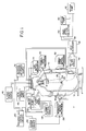
- Fig. 1 depicts a plasma system for use in carrying out methods according to the invention.
- the plasma system of Fig. 1 includes a plasma chamber 10 that provides a sealed vacuum-maintaining and pressure-resistant insulative enclosure.
- the chamber 10 is defined by a cylindrical principal body portion 12, and an upper lid portion 13 joined thereto.
- the body portion 12 of the plasma chamber 10 includes a bottom collector cone 14 that leads into and communicates with associated units for processing the exiting gases and particulates in maintaining the desired ambient pressure.
- a downwardly directed plasma stream is established by a plasma gun 16 mounted within the interior of the chamber lid 13, the position of which gun 16 is controlled by a plasma gun motion mechanism 18.
- Both parts of the plasma chamber 10 are advantageously constructed as double-walled, water-cooled enclosures and the lid 13 is removable for access to the operative parts.
- the gun motion mechanism 18 supports and controls the plasma gun 16 through sealed bearing and couplings in the walls of the chamber lid 13.
- a powder feed mechanism 20 also coupled to the chamber lid 13 provides controlled feed of a heated powder into the plasma stream through flexible tubes that are coupled to the plasma gun 16.
- the powder feed mechanism 20 is employed to introduce into the plasma stream metallic powder which is to be cleaned of oxide coating thereon or which is to be maintained relatively oxide-free in accordance with the invention.
- the downwardly directed plasma stream impinges on a workpiece 24 which is supported on an internally cooled conductive workpiece holder 25 and which is positioned and moved while in operation via a shaft extending through the chamber body 12 to an exterior workpiece motion mechanism 26.
- Both the workpiece holder 25 and dummy sting 28 are adjustable as to insert position with respect to the central axis of the chamber 10 and electrically conductive so that they may be held at selected potential levels for transfer arc generation during various phases of operation.
- the collector cone 14 directs the overspray gaseous and particulate materials into a baffle/filter module 32 having a water-cooled baffle section thereof for initially coupling the overspray and an in-line filter section thereof for extracting the majority of the entrained particle matter. Effluent passing through the baffle/filter module 32 is then directed through a heat-exchanger module 36, which may be another water-cooled unit, into a vacuum manifold 38 containing an overspray filter/collector unit 40 which extracts substantially all particulate remaining in the flow.
- the vacuum manifold 38 communicates with vacuum pumps 42 having sufficient capacity to maintain a desired ambient pressure within the chamber 10. This ambient pressure which is typically in the range from 60.8 KPa (0.6 atmospheres) down to 0.1 KPa (0.001 atmospheres) produces a static pressure sufficient to provide the plasma stream with supersonic speed.
- the baffle/filter module 32 and the heat-exchanger module 36, as well as the overspray filter/collector 40 are preferably double-walled water-cooled systems, and any of the types well known and widely used in plasma systems may be employed.
- the entire system may be mounted on rollers and movable along rails for ease of handling and servicing of different parts of the system. Conventional viewing windows, water-cooled access doors and insulated feedthrough plates for electrical connection have not been shown or discussed in detail, for simplicity of illustration.
- the workpiece support and motion control system is advantageously mounted in a hinged front access door 43 in the chamber body 12.
- Flexible water-cooled cables couple a plasma power source 46, a high frequency power supply 48 and a negative transfer arc power source via the bus bars 44 into the plasma gun 16 for generation of the plasma stream.
- the plasma power source 46 provides the requisite electrical potential difference between the electrodes of the plasma gun 16.
- the high frequency power supply 48 is used to initiate an arc within the plasma gun 16 by superimposing a high frequency voltage discharge on the D.C. power supply comprising the plasma power source 46.
- the negative transfer arc power source which is coupled between the plasma gun 16 and the workpiece 24 provides a continuous negative transfer arc therebetween in accordance with the invention.
- Operation of the plasma gun 16 entails usage of a water booster pump 52 to provide an adequate flow of cooling water through the interior of the plasma gun 16.
- a plasma gas source 54 provides a suitable ionizing gas for generation of the plasma stream.
- the plasma gas here employed is either argon along or argon seeded with helium or hydrogen, although other gases may be employed as is well known to those skilled in the art.
- Transfer arc control circuits 60 may be used to control the negative transfer arc power source 50.
- Fig. 1 Most of what has been shown and described in connection with Fig. 1 is similar to the plasma system described in previously referred to U.S. Patent 4,328,257 of Muehlberger et al., and reference thereto is made to the extent that further explanation of one or more portions of the plasma system may be needed.
- Fig. 2 is an idealized and simplified schematic view of a portion of the plasma system of Fig. 1 in which the workpiece 24 comprises a substrate 70.
- Fig. 2 depicts a plasma system for spraying metallic powder to form a coating on the substrate 70.
- the plasma gun 16 ionizes inert gas in the manner previously described to provide a plasma stream which extends between the plasma gun 16 and the substrate 70.
- the plasma stream is represented by a series of dashed lines 72.
- the negative transfer arc power source 50 is continuously coupled between the plasma gun 16 and the substrate 70.
- the negative transfer arc power source 50 has a positive terminal 74 which is coupled to the plasma gun 16.
- the negative transfer arc power source 50 has a negative terminal 76 which is coupled to the substrate 70. This causes the substrate 70 to act as a cathode. Accordingly, the negative transfer arc power supply 50 provides a continuous negative transfer arc in conjunction with the plasma stream 72 along a portion of the plasma stream 72 between the plasma gun 16 and the substrate 70.
- Metallic powder to be coated on the substrate 70 is provided by the powder feed mechanism 20 previously described in connection with Fig. 1.
- the powder feed mechanism 20 which is not shown in Fig. 2 includes a powder delivery tube 78 which terminates within the plasma gun 16 where the metallic powder is fed into the plasma stream 72.
- the substrate 70 which functions as a cathode relative to the plasma gun 16 by virtue of the negative transfer arc power source 50 emits electrons therefrom. This results in an electromagnetic propagation of electron current between the substrate 70 and the plasma gun 16.
- the flow of negative electrons from the substrate 70 encounters the particles and removes all or at least a substantial portion of any oxide coating present on the particles.
- the particles are substantially free of oxides.
- a continuous cleaning action is provided at the coating on the substrate 70, by virtue of which any oxides present at the coating continue to be removed therefrom.
- oxide coatings has been found to be particularly advantageous in the case of highly oxidizable refractory metals such as titanium, tantalum and even aluminum.
- the oxide coatings which are typically already present on such particles as a result of the powder forming process are removed from the particles as they travel to the substrate 70, resulting in a metallic coating on the substrate 70 which has a very low oxide content therein.
- Metallic particles introduced into the plasma stream 72 in a relatively pure, oxide-free form tend to remain so as they travel along the plasma stream 72 to the substrate 70.
- methods in accordance with the invention are advantageously used with metallic particles of all types including those which are highly oxidizable and those which oxidize at considerably lower rates.
- Fig. 4 is a photomicrograph, magnified 100 times, of a coating of titanium on a substrate such as the substrate 70 of Fig. 2.
- the titanium coating was placed on the substrate without using a negative transfer arc. It will be observed that the titanium coating has numerous dark spots therein, many of which are relatively large. The dark spots are voids and oxides in the coating.
- the coating in the example of Fig. 4 is regarded as being somewhat porous and having a rather high oxide content which is undesirable.
- Fig. 5 which is a photomicrograph, magnified 400 times, of a portion of the titanium coating and the substrate of Fig. 4 illustrates in even greater detail the significant voids and the substantial amount of oxides present in the titanium coating.
- Fig. 6 is a photomicrograph, magnified 100 times, of a titanium coating on a substrate.
- the titanium coating illustrated in Fig. 6 was applied using a continous negative transfer arc in the manner described in connection with Fig. 2. It will be observed that when compared with Fig. 4 the titanium coating of Fig. 6 has a substantially lower void and oxide content.
- the dark spots which represent voids and oxides are considerably fewer and smaller in size in Fig. 6.
- Fig. 7 is a photomicrograph, magnified 400 times, of a portion of the titanium coating and the substrate of Fig. 6.
- Fig. 7 illustrates in greater detail the low void and oxide content of the titanium coating applied in accordance with the invention, particularly when contrasted with the photomicrograph of similar magnification provided by Fig. 5.
- processes in accordance with the invention include the generation of a plasma stream such as the plasma stream 72 utilizing the plasma gun 16.
- the negative transfer arc power source 50 or other appropriate means is employed to continuously maintain a negative transfer arc in conjunction with the plasma stream 72 along a portion of the plasma stream 72.
- the negative transfer arc is maintained in conjunction with the plasma stream 72 along the entire length of the plasma stream 72 between the plasma gun 16 and the substrate 70.
- the plasma stream 72 may be employed in conjunction with the negative transfer arc to clean the surface of the substrate 70 where desired.
- the metal particles are entrained into and flow with the plasma stream 72 to the substrate 70, and in the process are cleansed of any oxide coatings thereon in the manner previously described.
- the metal particles are received by the substrate 70 where they form a coating thereon.
- the plasma stream 72 is provided with a supersonic speed. This is accomplished in the manner previously described in connection with Fig. 1 by use of the downstream vacuum pumps 42 to provide a relatively low static pressure in the region of the plasma gun 16 and the workpiece 24 or the substrate 70 within the plasma chamber 10.
- the metallic particles are coated on the surface of the substrate 70 in relatively oxide-free form, as well as being cleaned of oxide coatings in those instances where the particles are provided to the plasma stream 72 in an impure, oxide-coated form. It may be desirable in certain instances to clean the metallic particles by removing the oxide coatings therefrom without spraying the particles as a coating on a substrate. Such an arrangement for cleaning the metallic particles is shown in an idealized and simplified schematic form in Fig. 3.
- the arrangement of Fig. 3 is like that of Fig. 2, except that the cathode in the Fig. 3 arrangement is provided by a hollow, generally ring-shaped electrode 80.
- the electrode 80 which is coupled to the negative terminal 76 of the negative transfer arc power source 50 is disposed within the path of the plasma stream 72 so that the plasma stream 72 passes through the hollow interior thereof.
- the negative transfer arc power source 50 maintains a negative transfer arc along a portion of the plasma stream 72 extending from the plasma gun 16 to the electrode 80.
- the electrode 80 emits electrodes in the same manner as the substrate 70 in the arrangement of Fig. 2 to provide an electromagnetic propagation of electron current which removes oxide coatings from the metallic particles as the particles are conveyed by the plasma stream 72 from the plasma gun 16 to the electrode 80.
- the cleaned metallic particles are then collected by a receptacle 82 disposed within the path of the plasma stream 72 downstream of the electrode 80.
- the metallic powder which is introduced into the plasma stream 72 within the plasma gun 16 is thus cleansed of any oxide coatings thereon and then collected in a relatively pure form in the receptacle 82.
Description
- The present invention relates to plasma systems in which metal particles are sprayed by a plasma stream, and more particularly to a method of removing oxides from metallic powder particles introduced into a plasma stream.
- Refractory materials such as titanium and tantalum and even aluminum are difficult to produce in powdered form without an oxide layer being present on the surface of the powder particles. A typical process of forming the powder involves melting the metal and then introducing the molten metal into a gas stream. As the powder particles are formed, the highly oxidizable nature of the material causes an oxide layer to form on the outside of the particles. Such oxidation can be minimized by using other processes to form the powder, but such processes tend to be relatively expensive.
- A further problem arises when metallic powders, particularly those of a highly oxidazable nature, are to be coated on a substrate using a plasma stream. Even where the powder is produced in a relatively oxide-free form, the mere process of introducing the powder into a plasma stream for coating on the substrate typically results in some oxidation of the powder particles. This is particularly true of highly oxidizable materials such as titanium, tantalum and aluminum. Workers skilled in the art have observed the tendency of most metallic particles to undergo some oxidation as they are sprayed in a plasma stream. A natural reaction to this has been a desire to spray the powdered materials quickly so that they are deposited on the substrate before substantial oxidation occurs. However, the speed of the oxidation process has been difficult to determine. Moreover, even where supersonic speeds of the plasma steam are produced such as through the use of a vacuum source to provide low static pressure, some oxidation of the metallic particles is still observed.
- An example of a conventional supersonic plasma system is provided by U.S. Patent 4,328,257 issued on May 4, 1982. This patent describes a plasma system in which a vacuum source creates a low static pressure within an enclosure containing a plasma gun and a workpiece located downstream of the plasma gun. The plasma gun ionizes an inert gas to produce a plasma stream. The plasma stream flows from the plasma gun to the workpiece at supersonic speeds in the presence of the low static pressure provided by the vacuum source. Metallic powder introduced into the plasma stream at a location adjacent the plasma gun is carried to the workpiece where it is deposited on the workpiece as a coating.
- The plasma system described in the US 4,328,257 Patent employs switchable transfer arc power supplies which are advantageously employed to initially establish a negative or cathodic condition at the workpiece for purposes of cleaning the workpiece. Thereafter, the workpiece is made positive relative to the plasma gun to enhance the depositing of the metallic powders introduced into the plasma stream onto the workpiece. In spite of the supersonic speeds of the plasma stream, it has been observed that some oxidation of the metallic powder still occurs as it travels along the plasma stream. This is especially true in the case of the highly oxidizable refractory materials, even when such materials are introduced into the plasma stream in a relatively pure, oxide-free form. As previously noted such materials are difficult to produce in powdered form without the formation of an oxide coating on the particles, with the result that the less expensive processes for producing the metallic powders provide the powder particles with an oxide coating before they are even introduced into the plasma stream. All of this results in the presence of substantial oxides in the coating formed on the workpiece.
- An alternative plasma spraying method is provided by JP-A-56055562. The apparatus described operates without a vacuum or low pressure source. A continuous negative voltage is applied to the substrate during spraying. This removes any oxide film on the substrate and maintains a clean surface, thus encouraging the formation of a coating with superior adhesive strength.
- An alternative approach to the spraying of metallic powders in a plasma stream which minimises oxides is described in U.S. Patent 4,689,468 issued on August 25, 1987. In this patent, a main plasma gun and a second or clean-up plasma gun simultaneously provide transfer arcs of opposite polarities at a common workpiece or substrate, with the result that oxides at the workpiece or substrate are significantly reduced. However, such oxide reduction comes at the expense of a more elaborate system requiring the presence of the second plasma gum and a separate set of power supplies therefor.
- Accordingly, it would be advantageous to provide a process for removing the oxide coatings from highly oxidizable metal particles using a single plasma gun. It would furthermore be advantageous to provide a process for removing the oxide coatings from metal particles in conjunction with the spraying of such particles onto a workpiece or substrate.
- Oxide coatings are removed from metal particles in powdered form utilizing methods in accordance with the invention in which the particles are introduced into a plasma stream in the presence of a continuous negative transfer arc. The plasma stream is produced by ionizing an inert gas within a plasma gun. The plasma stream is provided with supersonic speed through the use of a vacuum source to provide a low static pressure. The continuous negative transfer arc is produced by continuously coupling a negative transfer arc power source between the plasma gun and a cathode located downstream from the plasma gun.
- The continuous presence or the negative transfer arc along a portion of the plasma stream between the plasma gun and the cathode produces an electron emission from the cathode. The electron emission produces an electromagnetic propagation of electron current. The electromagnetic propagation has been found to remove substantial portions of oxide coatings already formed on metallic particles traveling in the plasma stream between the plasma gun and the cathode, and to prevent such oxide layers from forming in instances where the metallic particles are introduced into the plasma stream in a relatively pure, oxide-free form. A continuous cleaning, oxide-removing process takes place at the cathode, which acts to continuously clean the metallic coating formed therein where the cathode comprises a substrate.
- In accordance with the invention, the continuous negative transfer arc can be employed to simply clean the metal particles by removing the oxide coatings therefrom, in which event the cleaned metal particles in the plasma stream are collected in a receptacle located downstream from the cathode. In such instances, the cathode may comprise a hollow, generally ring-shaped electrode disposed within the plasma stream so that the plasma stream flows through the hollow interior thereof.
- Further in accordance with the invention, the continuous negative transfer arc can be used to remove the oxide coatings from the metal particles prior to the particles forming a coating on a substrate or other workpiece. This is accomplished by coupling the substrate as the cathode. Following removal of the oxide coatings, the cleaned particles arrive at the substrate where they form a relatively oxide-free coating on the substrate.
- A better understanding of the invention may be had by reference to the following specification in conjunction with the accompanying drawings, in which:
- Fig. 1 is combined block diagram and perspective view, partially broken away, of a plasma system in which methods according to the invention can be carried out;
- Fig. 2 is an idealized and simplified schematic view of a portion of a plasma spray in accordance with the invention in which metallic particles are cleaned of oxide coatings before forming a coating on a substrate;
- Fig. 3 is an idealized and simplified schematic view of a portion of a plasma spray system in accordance with the invention in which metallic particles are cleaned of oxide coatings and then collected in powdered form;
- Fig. 4 is a photomicrograph, magnified 100 times, of a titanium coating formed on a substrate using a conventional process of the prior art;
- Fig. 5 is a photomicrograph, magnified 400 times, of a portion of the titanium coating and the substrate shown in Fig. 4;
- Fig. 6 is a photomicrograph, magnified 100 times, of a titanium coating formed on a substrate using a process in accordance with the invention; and
- Fig. 7 is a photomicrograph, magnified 400 times, of a portion of the titanium coating and the substrate shown in Fig. 6.
- Fig. 1 depicts a plasma system for use in carrying out methods according to the invention. The plasma system of Fig. 1 includes a
plasma chamber 10 that provides a sealed vacuum-maintaining and pressure-resistant insulative enclosure. Thechamber 10 is defined by a cylindricalprincipal body portion 12, and anupper lid portion 13 joined thereto. Thebody portion 12 of theplasma chamber 10 includes abottom collector cone 14 that leads into and communicates with associated units for processing the exiting gases and particulates in maintaining the desired ambient pressure. - A downwardly directed plasma stream is established by a
plasma gun 16 mounted within the interior of thechamber lid 13, the position of whichgun 16 is controlled by a plasmagun motion mechanism 18. Both parts of theplasma chamber 10 are advantageously constructed as double-walled, water-cooled enclosures and thelid 13 is removable for access to the operative parts. Thegun motion mechanism 18 supports and controls theplasma gun 16 through sealed bearing and couplings in the walls of thechamber lid 13. Apowder feed mechanism 20 also coupled to thechamber lid 13 provides controlled feed of a heated powder into the plasma stream through flexible tubes that are coupled to theplasma gun 16. Thepowder feed mechanism 20 is employed to introduce into the plasma stream metallic powder which is to be cleaned of oxide coating thereon or which is to be maintained relatively oxide-free in accordance with the invention. - The downwardly directed plasma stream impinges on a
workpiece 24 which is supported on an internally cooledconductive workpiece holder 25 and which is positioned and moved while in operation via a shaft extending through thechamber body 12 to an exteriorworkpiece motion mechanism 26. Adjacent one end of theworkpiece 24, but spaced apart therefrom, is a dummy workpiece ordummy sting 28, which is similarly internally cooled and coupled through a sidewall of thechamber body 12 to a dummysting motion mechanism 30. Both theworkpiece holder 25 anddummy sting 28 are adjustable as to insert position with respect to the central axis of thechamber 10 and electrically conductive so that they may be held at selected potential levels for transfer arc generation during various phases of operation. - Below the
workpiece 24 and thedummy sting 28 positions, thecollector cone 14 directs the overspray gaseous and particulate materials into a baffle/filter module 32 having a water-cooled baffle section thereof for initially coupling the overspray and an in-line filter section thereof for extracting the majority of the entrained particle matter. Effluent passing through the baffle/filter module 32 is then directed through a heat-exchanger module 36, which may be another water-cooled unit, into avacuum manifold 38 containing an overspray filter/collector unit 40 which extracts substantially all particulate remaining in the flow. Thevacuum manifold 38 communicates withvacuum pumps 42 having sufficient capacity to maintain a desired ambient pressure within thechamber 10. This ambient pressure which is typically in the range from 60.8 KPa (0.6 atmospheres) down to 0.1 KPa (0.001 atmospheres) produces a static pressure sufficient to provide the plasma stream with supersonic speed. - The baffle/
filter module 32 and the heat-exchanger module 36, as well as the overspray filter/collector 40 are preferably double-walled water-cooled systems, and any of the types well known and widely used in plasma systems may be employed. The entire system may be mounted on rollers and movable along rails for ease of handling and servicing of different parts of the system. Conventional viewing windows, water-cooled access doors and insulated feedthrough plates for electrical connection have not been shown or discussed in detail, for simplicity of illustration. The workpiece support and motion control system is advantageously mounted in a hingedfront access door 43 in thechamber body 12. - Electrical energy is supplied into the operative portions of the system via fixed bus bars 44 mounted on the top of the
chamber lid 13. Flexible water-cooled cables couple aplasma power source 46, a highfrequency power supply 48 and a negative transfer arc power source via the bus bars 44 into theplasma gun 16 for generation of the plasma stream. Theplasma power source 46 provides the requisite electrical potential difference between the electrodes of theplasma gun 16. The highfrequency power supply 48 is used to initiate an arc within theplasma gun 16 by superimposing a high frequency voltage discharge on the D.C. power supply comprising theplasma power source 46. Thereafter, the negative transfer arc power source which is coupled between theplasma gun 16 and theworkpiece 24 provides a continuous negative transfer arc therebetween in accordance with the invention. - Operation of the
plasma gun 16 entails usage of awater booster pump 52 to provide an adequate flow of cooling water through the interior of theplasma gun 16. Aplasma gas source 54 provides a suitable ionizing gas for generation of the plasma stream. The plasma gas here employed is either argon along or argon seeded with helium or hydrogen, although other gases may be employed as is well known to those skilled in the art. - Control of the sequencing of the system of Fig. 1 and the velocity and amplitude of motion of the various motion mechanisms is governed by a
system control console 56. Theplasma gun 16 is separately operated under control of aplasma control console 58. Inasmuch as the functions performed by these consoles and the circuits included therein are well understood, they have not been shown or described in detail. Transferarc control circuits 60 may be used to control the negative transferarc power source 50. - Most of what has been shown and described in connection with Fig. 1 is similar to the plasma system described in previously referred to U.S. Patent 4,328,257 of Muehlberger et al., and reference thereto is made to the extent that further explanation of one or more portions of the plasma system may be needed.
- Fig. 2 is an idealized and simplified schematic view of a portion of the plasma system of Fig. 1 in which the
workpiece 24 comprises asubstrate 70. As such, Fig. 2 depicts a plasma system for spraying metallic powder to form a coating on thesubstrate 70. Theplasma gun 16 ionizes inert gas in the manner previously described to provide a plasma stream which extends between theplasma gun 16 and thesubstrate 70. The plasma stream is represented by a series of dashedlines 72. - The negative transfer
arc power source 50 is continuously coupled between theplasma gun 16 and thesubstrate 70. The negative transferarc power source 50 has apositive terminal 74 which is coupled to theplasma gun 16. The negative transferarc power source 50 has anegative terminal 76 which is coupled to thesubstrate 70. This causes thesubstrate 70 to act as a cathode. Accordingly, the negative transferarc power supply 50 provides a continuous negative transfer arc in conjunction with theplasma stream 72 along a portion of theplasma stream 72 between theplasma gun 16 and thesubstrate 70. Metallic powder to be coated on thesubstrate 70 is provided by thepowder feed mechanism 20 previously described in connection with Fig. 1. Thepowder feed mechanism 20 which is not shown in Fig. 2 includes apowder delivery tube 78 which terminates within theplasma gun 16 where the metallic powder is fed into theplasma stream 72. - In accordance with the invention, the
substrate 70 which functions as a cathode relative to theplasma gun 16 by virtue of the negative transferarc power source 50 emits electrons therefrom. This results in an electromagnetic propagation of electron current between thesubstrate 70 and theplasma gun 16. As the metallic particles of the powder travel in the plasma stream from theplasma gun 16 to thesubstrate 70, the flow of negative electrons from thesubstrate 70 encounters the particles and removes all or at least a substantial portion of any oxide coating present on the particles. When the particles reach thesubstrate 70 to form a coating thereon, the particles are substantially free of oxides. In addition, a continuous cleaning action is provided at the coating on thesubstrate 70, by virtue of which any oxides present at the coating continue to be removed therefrom. - The removal of oxide coatings has been found to be particularly advantageous in the case of highly oxidizable refractory metals such as titanium, tantalum and even aluminum. Where particles of such metals are introduced into the
plasma stream 72, the oxide coatings which are typically already present on such particles as a result of the powder forming process are removed from the particles as they travel to thesubstrate 70, resulting in a metallic coating on thesubstrate 70 which has a very low oxide content therein. Metallic particles introduced into theplasma stream 72 in a relatively pure, oxide-free form tend to remain so as they travel along theplasma stream 72 to thesubstrate 70. Thus, methods in accordance with the invention are advantageously used with metallic particles of all types including those which are highly oxidizable and those which oxidize at considerably lower rates. - The oxide reduction produced by the use of a continuous negative transfer arc in accordance with the invention can be beeter appreciated by referring to the photomicrographs of Figs. 4-7.
- Fig. 4 is a photomicrograph, magnified 100 times, of a coating of titanium on a substrate such as the
substrate 70 of Fig. 2. The titanium coating was placed on the substrate without using a negative transfer arc. It will be observed that the titanium coating has numerous dark spots therein, many of which are relatively large. The dark spots are voids and oxides in the coating. The coating in the example of Fig. 4 is regarded as being somewhat porous and having a rather high oxide content which is undesirable. - Fig. 5 which is a photomicrograph, magnified 400 times, of a portion of the titanium coating and the substrate of Fig. 4 illustrates in even greater detail the significant voids and the substantial amount of oxides present in the titanium coating.
- Fig. 6 is a photomicrograph, magnified 100 times, of a titanium coating on a substrate. The titanium coating illustrated in Fig. 6 was applied using a continous negative transfer arc in the manner described in connection with Fig. 2. It will be observed that when compared with Fig. 4 the titanium coating of Fig. 6 has a substantially lower void and oxide content. The dark spots which represent voids and oxides are considerably fewer and smaller in size in Fig. 6.
- Fig. 7 is a photomicrograph, magnified 400 times, of a portion of the titanium coating and the substrate of Fig. 6. Fig. 7 illustrates in greater detail the low void and oxide content of the titanium coating applied in accordance with the invention, particularly when contrasted with the photomicrograph of similar magnification provided by Fig. 5.
- Referring again to Fig. 2, it will be understood that processes in accordance with the invention include the generation of a plasma stream such as the
plasma stream 72 utilizing theplasma gun 16. The negative transferarc power source 50 or other appropriate means is employed to continuously maintain a negative transfer arc in conjunction with theplasma stream 72 along a portion of theplasma stream 72. In the example of Fig. 2 the negative transfer arc is maintained in conjunction with theplasma stream 72 along the entire length of theplasma stream 72 between theplasma gun 16 and thesubstrate 70. Prior to the introduction of the powdered metal into theplasma stream 72, theplasma stream 72 may be employed in conjunction with the negative transfer arc to clean the surface of thesubstrate 70 where desired. As the particles of the powdered metal are introduced into theplasma stream 72 within theplasma gun 16, the metal particles are entrained into and flow with theplasma stream 72 to thesubstrate 70, and in the process are cleansed of any oxide coatings thereon in the manner previously described. The metal particles are received by thesubstrate 70 where they form a coating thereon. - The
plasma stream 72 is provided with a supersonic speed. This is accomplished in the manner previously described in connection with Fig. 1 by use of thedownstream vacuum pumps 42 to provide a relatively low static pressure in the region of theplasma gun 16 and theworkpiece 24 or thesubstrate 70 within theplasma chamber 10. - In the example of Fig. 2, the metallic particles are coated on the surface of the
substrate 70 in relatively oxide-free form, as well as being cleaned of oxide coatings in those instances where the particles are provided to theplasma stream 72 in an impure, oxide-coated form. It may be desirable in certain instances to clean the metallic particles by removing the oxide coatings therefrom without spraying the particles as a coating on a substrate. Such an arrangement for cleaning the metallic particles is shown in an idealized and simplified schematic form in Fig. 3. - The arrangement of Fig. 3 is like that of Fig. 2, except that the cathode in the Fig. 3 arrangement is provided by a hollow, generally ring-shaped
electrode 80. Theelectrode 80 which is coupled to thenegative terminal 76 of the negative transferarc power source 50 is disposed within the path of theplasma stream 72 so that theplasma stream 72 passes through the hollow interior thereof. The negative transferarc power source 50 maintains a negative transfer arc along a portion of theplasma stream 72 extending from theplasma gun 16 to theelectrode 80. Theelectrode 80 emits electrodes in the same manner as thesubstrate 70 in the arrangement of Fig. 2 to provide an electromagnetic propagation of electron current which removes oxide coatings from the metallic particles as the particles are conveyed by theplasma stream 72 from theplasma gun 16 to theelectrode 80. The cleaned metallic particles are then collected by areceptacle 82 disposed within the path of theplasma stream 72 downstream of theelectrode 80. The metallic powder which is introduced into theplasma stream 72 within theplasma gun 16 is thus cleansed of any oxide coatings thereon and then collected in a relatively pure form in thereceptacle 82. - While various forms and modifications have been suggested, it will be appreciated that the invention is not limited thereto but encompasses all expedients and variations falling within the scope of the appended claims.
Claims (9)
- A method of cleansing metal particles of oxides comprising the steps of:
operating a plasma gun in the presence of a source of reduced pressure to generate a supersonic plasma stream;
continuously maintaining a negative transfer arc in conjunction with the plasma stream along a portion of the plasma stream;
introducing metal particles into the plasma stream; and
receiving the metal particles after they have travelled along said portion of the plasma stream. - A method as claimed in claim 1, wherein the step of receiving the metal particles comprises placing a substrate at an end of said portion of the plasma stream so that the metal particles form a coating on the substrate.
- A method as claimed in claim 1, wherein the step of receiving the metal particles comprises placing a container downstream from said portion of the plasma stream to catch the metal particles in the plasma stream.
- A method as claimed in claim 2 wherein the step of operating a plasma gun comprises locating a vacuum source downstream of the substrate from the plasma gun to provide a low static pressure and ionizing a gas stream in the plasma gun to produce a plasma stream which travels to the substrate at supersonic speeds in the presence of the low static pressure.
- A method as claimed in any of the preceding claims wherein the step of continuously maintaining a negative transfer arc comprises continuously coupling a negative transfer arc power source between the plasma gun and a location at an end of said portion opposite the plasma gun.
- A method as claimed in any of the preceding claims wherein the step of introducing metal particles comprises introducing metal particles into the plasma stream within the plasma gun.
- A method as claimed in any of the preceding claims wherein the step of introducing the metal particles into the plasma stream comprises introducing powdered metal chosen from the group consisting of titanium, tantalum and aluminum.
- A method as claimed in claim 1 wherein the step of receiving the metal particles includes the step of providing a receptacle, the step of introducing metal particles into the plasma stream comprises the step of introducing the oxidized metal particles into the plasma stream at a location adjacent the plasma gun, and the step of continuously maintaining a negative transfer arc in conjunction with the plasma stream along a portion of the plasma stream comprises the steps of locating an electrode within the plasma stream adjacent the receptacle and continuously coupling a negative transfer arc power source between the plasma gun and the electrode to provide a negative transfer arc between the plasma gun and the electrode.
- A method as claimed in claim 8 wherein the step of locating an electrode within the plasma stream comprises locating a ring-shaped electrode adjacent the receptacle so that the plasma stream may pass through a hollow interior of the ring-shaped electrode.
Applications Claiming Priority (2)
| Application Number | Priority Date | Filing Date | Title |
|---|---|---|---|
| US07/181,400 US4877640A (en) | 1988-04-13 | 1988-04-13 | Method of oxide removal from metallic powder |
| US181400 | 1988-04-13 |
Publications (2)
| Publication Number | Publication Date |
|---|---|
| EP0341835A1 EP0341835A1 (en) | 1989-11-15 |
| EP0341835B1 true EP0341835B1 (en) | 1993-02-10 |
Family
ID=22664120
Family Applications (1)
| Application Number | Title | Priority Date | Filing Date |
|---|---|---|---|
| EP89303674A Expired - Lifetime EP0341835B1 (en) | 1988-04-13 | 1989-04-13 | Method of oxide removal from metallic powder |
Country Status (5)
| Country | Link |
|---|---|
| US (1) | US4877640A (en) |
| EP (1) | EP0341835B1 (en) |
| JP (1) | JPH0660321B2 (en) |
| CA (1) | CA1337486C (en) |
| DE (1) | DE68904804T2 (en) |
Families Citing this family (10)
| Publication number | Priority date | Publication date | Assignee | Title |
|---|---|---|---|---|
| US5176938A (en) * | 1988-11-23 | 1993-01-05 | Plasmacarb Inc. | Process for surface treatment of pulverulent material |
| US5254237A (en) * | 1991-03-01 | 1993-10-19 | Snaper Alvin A | Plasma arc apparatus for producing diamond semiconductor devices |
| US5284503A (en) * | 1992-11-10 | 1994-02-08 | Exide Corporation | Process for remediation of lead-contaminated soil and waste battery |
| US5439498A (en) * | 1992-11-10 | 1995-08-08 | Exide Corporation | Process and system for the on-site remediation of lead-contaminated soil and waste battery casings |
| WO1997010774A1 (en) * | 1995-09-19 | 1997-03-27 | Exide Corporation | Process for the destruction of chemical agents and munitions |
| US5681486A (en) * | 1996-02-23 | 1997-10-28 | The Boeing Company | Plasma descaling of titanium and titanium alloys |
| US5942023A (en) * | 1997-02-12 | 1999-08-24 | Exide Corporation | Process for recovering metals from electric arc furnace (EAF) dust |
| US6043451A (en) * | 1997-11-06 | 2000-03-28 | Promet Technologies, Inc. | Plasma spraying of nickel-titanium compound |
| US6915964B2 (en) * | 2001-04-24 | 2005-07-12 | Innovative Technology, Inc. | System and process for solid-state deposition and consolidation of high velocity powder particles using thermal plastic deformation |
| US7691177B2 (en) * | 2006-10-30 | 2010-04-06 | Niotan, Inc. | Method and an apparatus of plasma processing of tantalum particles |
Family Cites Families (9)
| Publication number | Priority date | Publication date | Assignee | Title |
|---|---|---|---|---|
| GB740368A (en) * | 1951-11-22 | 1955-11-09 | Martin Von Schulthess | A method for the spraying of metals |
| SE320250B (en) * | 1965-09-01 | 1970-02-02 | Libbey Owens Ford Glass Co | |
| US3429691A (en) * | 1966-08-19 | 1969-02-25 | Aerojet General Co | Plasma reduction of titanium dioxide |
| US3839618A (en) * | 1972-01-03 | 1974-10-01 | Geotel Inc | Method and apparatus for effecting high-energy dynamic coating of substrates |
| US3989511A (en) * | 1975-03-10 | 1976-11-02 | Westinghouse Electric Corporation | Metal powder production by direct reduction in an arc heater |
| US4328257A (en) * | 1979-11-26 | 1982-05-04 | Electro-Plasma, Inc. | System and method for plasma coating |
| US4642440A (en) * | 1984-11-13 | 1987-02-10 | Schnackel Jay F | Semi-transferred arc in a liquid stabilized plasma generator and method for utilizing the same |
| DE3538390A1 (en) * | 1985-10-29 | 1987-04-30 | Deutsche Forsch Luft Raumfahrt | COATING FOR A SUBSTRATE AND METHOD FOR THE PRODUCTION THEREOF |
| US4784159A (en) * | 1986-08-19 | 1988-11-15 | Cordis Corporation | Process for making an implantable device having plasma sprayed metallic porous surface |
-
1988
- 1988-04-13 US US07/181,400 patent/US4877640A/en not_active Expired - Lifetime
-
1989
- 1989-04-12 CA CA000596423A patent/CA1337486C/en not_active Expired - Fee Related
- 1989-04-13 DE DE8989303674T patent/DE68904804T2/en not_active Expired - Lifetime
- 1989-04-13 EP EP89303674A patent/EP0341835B1/en not_active Expired - Lifetime
- 1989-04-13 JP JP1094286A patent/JPH0660321B2/en not_active Expired - Lifetime
Also Published As
| Publication number | Publication date |
|---|---|
| EP0341835A1 (en) | 1989-11-15 |
| CA1337486C (en) | 1995-10-31 |
| JPH0250901A (en) | 1990-02-20 |
| JPH0660321B2 (en) | 1994-08-10 |
| DE68904804T2 (en) | 1993-05-27 |
| DE68904804D1 (en) | 1993-03-25 |
| US4877640A (en) | 1989-10-31 |
Similar Documents
| Publication | Publication Date | Title |
|---|---|---|
| US4328257A (en) | System and method for plasma coating | |
| EP0341835B1 (en) | Method of oxide removal from metallic powder | |
| US4853250A (en) | Process of depositing particulate material on a substrate | |
| EP0241110B1 (en) | Oxide reduction in a plasma coating environment | |
| US5562841A (en) | Methods and apparatus for treating a work surface | |
| EP0378673A4 (en) | Method and apparatus for atomization and spraying of molten metals | |
| US8465809B2 (en) | Multiarc discharge moving bed reactor system | |
| US20160288211A1 (en) | Multi-metal particle generator and method | |
| AU2003224204A1 (en) | Method for the plasma cleaning of the surface of a material coated with an organic substance and the installation for carrying out said method | |
| CN105349955B (en) | Integrated anode in magnetron sputtering apparatus and active reaction gas source device | |
| CN1223241C (en) | Constant-pressure radio frequency cold plasma system and spray gun thereof | |
| EP0259459B1 (en) | Powder atomizing methods and apparatus | |
| EP0468110B1 (en) | Electric arc treatment of parts | |
| JPH01152627A (en) | Apparatus for plasma treatment | |
| EP3766609A1 (en) | Method and device for purging a production space for metal powder production | |
| JP3336541B2 (en) | Gas circulation method in gas deposition method and gas circulation device for gas deposition equipment | |
| JPH0775689B2 (en) | Thermal plasma jet generator | |
| JPH0225986B2 (en) | ||
| RU2167743C2 (en) | Device for production of ultradispersed powders | |
| JPH03104828A (en) | Method of reducing contamination of high temperature melt | |
| JPH07258844A (en) | Film forming device utilizing discharge plasma of magnetic neutral line | |
| JPH05339699A (en) | Plasma thermal spraying method | |
| JPH03173124A (en) | Plasma vapor growth apparatus | |
| JPS63307254A (en) | Apparatus for forming thin oxide film | |
| JPH06299315A (en) | Surface modifying method for aluminum and titanium |
Legal Events
| Date | Code | Title | Description |
|---|---|---|---|
| PUAI | Public reference made under article 153(3) epc to a published international application that has entered the european phase |
Free format text: ORIGINAL CODE: 0009012 |
|
| AK | Designated contracting states |
Kind code of ref document: A1 Designated state(s): CH DE FR GB IT LI NL SE |
|
| 17P | Request for examination filed |
Effective date: 19900316 |
|
| 17Q | First examination report despatched |
Effective date: 19910517 |
|
| ITF | It: translation for a ep patent filed |
Owner name: LENZI & C. |
|
| GRAA | (expected) grant |
Free format text: ORIGINAL CODE: 0009210 |
|
| AK | Designated contracting states |
Kind code of ref document: B1 Designated state(s): CH DE FR GB IT LI NL SE |
|
| REF | Corresponds to: |
Ref document number: 68904804 Country of ref document: DE Date of ref document: 19930325 |
|
| ET | Fr: translation filed | ||
| PLBE | No opposition filed within time limit |
Free format text: ORIGINAL CODE: 0009261 |
|
| STAA | Information on the status of an ep patent application or granted ep patent |
Free format text: STATUS: NO OPPOSITION FILED WITHIN TIME LIMIT |
|
| 26N | No opposition filed | ||
| EAL | Se: european patent in force in sweden |
Ref document number: 89303674.9 |
|
| REG | Reference to a national code |
Ref country code: CH Ref legal event code: PUE Owner name: ELECTRO-PLASMA, INC. TRANSFER- SULZER METCO AG |
|
| REG | Reference to a national code |
Ref country code: GB Ref legal event code: 732E |
|
| NLS | Nl: assignments of ep-patents |
Owner name: SULZER METCO AG |
|
| REG | Reference to a national code |
Ref country code: FR Ref legal event code: TP |
|
| REG | Reference to a national code |
Ref country code: FR Ref legal event code: CD |
|
| PGFP | Annual fee paid to national office [announced via postgrant information from national office to epo] |
Ref country code: SE Payment date: 20000320 Year of fee payment: 12 Ref country code: NL Payment date: 20000320 Year of fee payment: 12 |
|
| PG25 | Lapsed in a contracting state [announced via postgrant information from national office to epo] |
Ref country code: SE Free format text: LAPSE BECAUSE OF NON-PAYMENT OF DUE FEES Effective date: 20010414 |
|
| PG25 | Lapsed in a contracting state [announced via postgrant information from national office to epo] |
Ref country code: NL Free format text: LAPSE BECAUSE OF NON-PAYMENT OF DUE FEES Effective date: 20011101 |
|
| EUG | Se: european patent has lapsed |
Ref document number: 89303674.9 |
|
| REG | Reference to a national code |
Ref country code: GB Ref legal event code: IF02 |
|
| NLV4 | Nl: lapsed or anulled due to non-payment of the annual fee |
Effective date: 20011101 |
|
| PG25 | Lapsed in a contracting state [announced via postgrant information from national office to epo] |
Ref country code: IT Free format text: LAPSE BECAUSE OF NON-PAYMENT OF DUE FEES;WARNING: LAPSES OF ITALIAN PATENTS WITH EFFECTIVE DATE BEFORE 2007 MAY HAVE OCCURRED AT ANY TIME BEFORE 2007. THE CORRECT EFFECTIVE DATE MAY BE DIFFERENT FROM THE ONE RECORDED. Effective date: 20050413 |
|
| PGFP | Annual fee paid to national office [announced via postgrant information from national office to epo] |
Ref country code: CH Payment date: 20080415 Year of fee payment: 20 Ref country code: DE Payment date: 20080418 Year of fee payment: 20 |
|
| PGFP | Annual fee paid to national office [announced via postgrant information from national office to epo] |
Ref country code: FR Payment date: 20080412 Year of fee payment: 20 |
|
| PGFP | Annual fee paid to national office [announced via postgrant information from national office to epo] |
Ref country code: GB Payment date: 20080421 Year of fee payment: 20 |
|
| REG | Reference to a national code |
Ref country code: CH Ref legal event code: PL |
|
| REG | Reference to a national code |
Ref country code: GB Ref legal event code: PE20 Expiry date: 20090412 |
|
| PG25 | Lapsed in a contracting state [announced via postgrant information from national office to epo] |
Ref country code: GB Free format text: LAPSE BECAUSE OF EXPIRATION OF PROTECTION Effective date: 20090412 |