EP0341701A2 - Bildverarbeitungsverfahren - Google Patents
Bildverarbeitungsverfahren Download PDFInfo
- Publication number
- EP0341701A2 EP0341701A2 EP19890108437 EP89108437A EP0341701A2 EP 0341701 A2 EP0341701 A2 EP 0341701A2 EP 19890108437 EP19890108437 EP 19890108437 EP 89108437 A EP89108437 A EP 89108437A EP 0341701 A2 EP0341701 A2 EP 0341701A2
- Authority
- EP
- European Patent Office
- Prior art keywords
- boundary pixels
- concavity
- image processing
- processing method
- configuration
- Prior art date
- Legal status (The legal status is an assumption and is not a legal conclusion. Google has not performed a legal analysis and makes no representation as to the accuracy of the status listed.)
- Granted
Links
Images


Classifications
-
- G—PHYSICS
- G06—COMPUTING OR CALCULATING; COUNTING
- G06V—IMAGE OR VIDEO RECOGNITION OR UNDERSTANDING
- G06V10/00—Arrangements for image or video recognition or understanding
- G06V10/40—Extraction of image or video features
- G06V10/46—Descriptors for shape, contour or point-related descriptors, e.g. scale invariant feature transform [SIFT] or bags of words [BoW]; Salient regional features
Definitions
- the present invention relates to an image processing method for calculating characteristics parameters of a concavity.
- concavities 1 and 2 and a hole are important characteristics. Therefore, convexity and concavity are important characteristics of a configuration.
- the smallest convex configuration including a configuration to be processed (original configuration hereinafter) is called convex hull. By subtracting the original configuration from the convex hull, concavities and holes are extracted, for characterizing the original configuration.
- the convex hull cannot easily generated in the strict meaning, in the conventional method. In the conventional method, top points of convex hull are successively connected by straight lines.
- a straight line is different from a line in the mathematical meaning, because a digital image consists of dispersed pixels and mathematical continuous line cannot always be drawn.
- the digital line may be an approximation and pixels outside of the convex hull may be took as pixels on the line.
- the configurations generated by the above subtraction represent other characteristics than the characteristics to be extracted.
- a graphic processor is used for drawing lines, so lines are drawn according to the algorithm of the processor. It is not guaranteed that a suitable convex hull for recognition is always generated.
- chord length of a concavity For evaluating a concavity, several characteristic parameters are proposed; chord length of a concavity, inner peripheral length of a concavity, concavity ratio etc. Unless concavities are exactly extracted, calculation of these parameters become in vain.
- the present invention has an object to provide an image processing method for extracting exact concavities.
- each border pixel has or from the distance between each pixels and a line connecting the top points so as to found the boundary pixels defines concavity or not.
- Fig. 1 shows a configuration including concavities A, B, C, D and E, hatched.
- a horizontal rectangle R circumscribed about the configuration is shown, as well.
- the configuration is divided into quadrants from first to fourth by the rectangle R.
- boundary pixels from upper side left contact point to left side lower contact point belong to the first quadrant
- boundary pixels from left side lower contact point to lower side right contact point belong to the second quadrant
- boundary pixels from lower side right contact point to right side upper contact point belong to the third quadrant
- boundary pixels from right side upper contact point to upper side left contact point belong to the fourth quadrant.
- the number of first to fourth may be changed as far as they are defined according to predetermined rule.
- the information concerning quadrant is important for the processing below.
- a table in Fig. 2 is generated, which includes informations of boundary pixels arranged in chain code order; whether they are top points on convex hull; x- and y-coordinates thereof; to which quadrant the points belong.
- top points on convex hull are indicated by Y or N, Y means to points and N means not.
- Figs. from 3(a) to 3(d) show the relationship between the quadrant and the chain code.
- Fig. 3(a) shows chain codes of boundary pixels in the first quadrant but not in a concavity.
- Fig. 3(b) shows chain codes of boundary pixels in the second quadrant but not in a concavity.
- Fig. 3(c) shows chain codes of boundary pixels in the third quadrant but not in a concavity.
- Fig. 3(d) shows chain codes of boundary pixels in the fourth quadrant but not in a concavity.
- chain code other than from 4 to 6 in the first quadrant indicates a concavity
- chain code other than from 6 to 0 in the second quadrant indicates a concavity
- chain code other than from 0 to 2 in the third quadrant indicates a concavity
- chain code other than from 2 to 4 in the fourth quadrant indicates a concavity.
- top points P1 and P2 on the convex hull are found.
- the inclination of the line l connecting P1 and P2 is calculated.
- boundary pixels are traced from P1 to P2.
- the distances between the line l and the boundary pixels are evaluated.
- a relationship between the chain code and distance increment ⁇ d is calculated in advance.
- the distance increment ⁇ d of boundary pixels traced are integrated so as to calculate a distance between the line l and the boundary pixel just traced.
- ⁇ d is defined as positive when it has inward direction from the line l.
- boundary pixels between adjacent top points defines a concavity when one or more boundary pixels have distance not less than "1" from the line connecting the top points.
- the pixel Pb6 has distance of "1.135". On tracing boundary pixels from Pb1 toward Pb7, it is found first on the point Pb6 that the boundary pixels define concavity.
- the inner peripheral length of a concavity is calculated. If it is found that the boundary pixels do not define a concavity, the counted value is canceled.
- chord length of a concavity is calculated by calculating distance between top points P1 and P2.
- the distance is calculated by the x- and y-coordinates of P1 and P2.
- Fig. 5 shows another configuration to be processed.
- the configuration has boundary pixels from Pb1 to Pb9 between top points P1 and P2.
- the distances of each boundary pixel from the line l connecting P1 and P2 are shown in Table 3.
- Table 3 Boundary pixel Distance Pb1 0.640 Pb2 1.280 Pb3 0.512 Pb4 1.152 Pb5 1.792 Pb6 2.432 Pb7 1.664 Pb8 0.896 Pb9 0.128
- concavity may be defined in two manners. In the first manner, one concavity is defined by the boundary pixels from Pb1 to Pb9. In the second manner, two concavities are defined, that is, one concavity is defined by the boundary pixels from Pb1 to Pb3 and the other concavity is defined by the boundary pixels from Pb4 to Pb9.
- Table 1 shows distance increment in the first quadrant.
- Table 4 shows distance increment in the quadrants from the second to the fourth.
- the inclination angle ⁇ is defined for each quadrant as shown in Fig. 6.
- Table 4 Quadrant Chain code ⁇ d II 6 cos ⁇ 7 sin ⁇ +cos ⁇ 0 sin ⁇ III 0 -sin ⁇ 1 cos ⁇ -sin ⁇ 2 cos ⁇ IV 2 cos ⁇ 3 -sin ⁇ -cos ⁇ 4 sin ⁇
- a concavity is defined when one or more boundary pixels has distance not less than "1". Such distance may be another value, for example "2" considering noises.
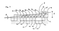
- Fig. 7 shows two adjacent top points a and b on convex hull as well as boundary pixels C1 to C9 therebetween.
- Top points a and b are connected with a line l for defining an inclination from a to b.
- continuous pixel train is generated from a to b.
- Each pixel of the train is inside of the line as well as the nearest pixel among pixels continuous to the previous pixel on the train. In this case, the pixel train is generated anticlockwisely. Clockwise pixel train may also be applied.
- the chain code of each pixel of the chain code train is limited to be "4" or "5".
- the pixel d′ of chain code "4" next to a is nearer than the pixel d1 of chain code "5". However the pixel of chain code "4" is outside of the line l. Then the pixel d1 is selected. Thereafter, pixels inside of the line l as well as nearest to the line l among the pixels continuous to the previous pixel on the pixel train. The pixels from d2 to d8 are to be selected.
- the convex hull is exactly generated by the method above.
- chord length is defined by the number of indexed pixels.
- the number of boundary pixels without index defines the inner peripheral length of concavity.
Landscapes
- Engineering & Computer Science (AREA)
- Computer Vision & Pattern Recognition (AREA)
- Physics & Mathematics (AREA)
- General Physics & Mathematics (AREA)
- Multimedia (AREA)
- Theoretical Computer Science (AREA)
- Image Analysis (AREA)
- Image Processing (AREA)
Applications Claiming Priority (2)
| Application Number | Priority Date | Filing Date | Title |
|---|---|---|---|
| JP115757/88 | 1988-05-12 | ||
| JP63115757A JP2739130B2 (ja) | 1988-05-12 | 1988-05-12 | 画像処理方法 |
Publications (3)
| Publication Number | Publication Date |
|---|---|
| EP0341701A2 true EP0341701A2 (de) | 1989-11-15 |
| EP0341701A3 EP0341701A3 (de) | 1991-10-09 |
| EP0341701B1 EP0341701B1 (de) | 1995-08-02 |
Family
ID=14670297
Family Applications (1)
| Application Number | Title | Priority Date | Filing Date |
|---|---|---|---|
| EP89108437A Expired - Lifetime EP0341701B1 (de) | 1988-05-12 | 1989-05-10 | Bildverarbeitungsverfahren |
Country Status (4)
| Country | Link |
|---|---|
| US (1) | US5159645A (de) |
| EP (1) | EP0341701B1 (de) |
| JP (1) | JP2739130B2 (de) |
| DE (1) | DE68923650T2 (de) |
Families Citing this family (37)
| Publication number | Priority date | Publication date | Assignee | Title |
|---|---|---|---|---|
| US6067379A (en) * | 1988-12-09 | 2000-05-23 | Cognex Corporation | Method and apparatus for locating patterns in an optical image |
| US5553196A (en) * | 1989-04-05 | 1996-09-03 | Yozan, Inc. | Method for processing data using a neural network having a number of layers equal to an abstraction degree of the pattern to be processed |
| US5754701A (en) * | 1992-08-11 | 1998-05-19 | Nec Corporation | Image signal coding method |
| US5590220A (en) * | 1992-08-12 | 1996-12-31 | International Business Machines Corporation | Bending point extraction method for optical character recognition system |
| JP2710202B2 (ja) * | 1993-03-24 | 1998-02-10 | インターナショナル・ビジネス・マシーンズ・コーポレイション | 閉じた輪郭イメージを凸多角形で境界づける方法及びデータ処理装置 |
| US5649024A (en) * | 1994-11-17 | 1997-07-15 | Xerox Corporation | Method for color highlighting of black and white fonts |
| US5668891A (en) * | 1995-01-06 | 1997-09-16 | Xerox Corporation | Methods for determining font attributes of characters |
| US5801966A (en) * | 1995-07-24 | 1998-09-01 | Cognex Corporation | Machine vision methods and articles of manufacture for determination of convex hull and convex hull angle |
| US6026176A (en) * | 1995-07-25 | 2000-02-15 | Cognex Corporation | Machine vision methods and articles of manufacture for ball grid array inspection |
| US5872870A (en) * | 1996-02-16 | 1999-02-16 | Cognex Corporation | Machine vision methods for identifying extrema of objects in rotated reference frames |
| US5909504A (en) * | 1996-03-15 | 1999-06-01 | Cognex Corporation | Method of testing a machine vision inspection system |
| US6298149B1 (en) | 1996-03-21 | 2001-10-02 | Cognex Corporation | Semiconductor device image inspection with contrast enhancement |
| US6259827B1 (en) | 1996-03-21 | 2001-07-10 | Cognex Corporation | Machine vision methods for enhancing the contrast between an object and its background using multiple on-axis images |
| US5978502A (en) * | 1996-04-01 | 1999-11-02 | Cognex Corporation | Machine vision methods for determining characteristics of three-dimensional objects |
| US6137893A (en) * | 1996-10-07 | 2000-10-24 | Cognex Corporation | Machine vision calibration targets and methods of determining their location and orientation in an image |
| US5960125A (en) | 1996-11-21 | 1999-09-28 | Cognex Corporation | Nonfeedback-based machine vision method for determining a calibration relationship between a camera and a moveable object |
| US5953130A (en) * | 1997-01-06 | 1999-09-14 | Cognex Corporation | Machine vision methods and apparatus for machine vision illumination of an object |
| US6075881A (en) * | 1997-03-18 | 2000-06-13 | Cognex Corporation | Machine vision methods for identifying collinear sets of points from an image |
| US5974169A (en) * | 1997-03-20 | 1999-10-26 | Cognex Corporation | Machine vision methods for determining characteristics of an object using boundary points and bounding regions |
| US6141033A (en) * | 1997-05-15 | 2000-10-31 | Cognex Corporation | Bandwidth reduction of multichannel images for machine vision |
| US6608647B1 (en) | 1997-06-24 | 2003-08-19 | Cognex Corporation | Methods and apparatus for charge coupled device image acquisition with independent integration and readout |
| US5978080A (en) * | 1997-09-25 | 1999-11-02 | Cognex Corporation | Machine vision methods using feedback to determine an orientation, pixel width and pixel height of a field of view |
| US6025854A (en) * | 1997-12-31 | 2000-02-15 | Cognex Corporation | Method and apparatus for high speed image acquisition |
| US6282328B1 (en) | 1998-01-28 | 2001-08-28 | Cognex Corporation | Machine vision systems and methods for morphological transformation of an image with non-uniform offsets |
| US6236769B1 (en) | 1998-01-28 | 2001-05-22 | Cognex Corporation | Machine vision systems and methods for morphological transformation of an image with zero or other uniform offsets |
| US6381375B1 (en) | 1998-02-20 | 2002-04-30 | Cognex Corporation | Methods and apparatus for generating a projection of an image |
| US6215915B1 (en) | 1998-02-20 | 2001-04-10 | Cognex Corporation | Image processing methods and apparatus for separable, general affine transformation of an image |
| US6687402B1 (en) | 1998-12-18 | 2004-02-03 | Cognex Corporation | Machine vision methods and systems for boundary feature comparison of patterns and images |
| US6381366B1 (en) | 1998-12-18 | 2002-04-30 | Cognex Corporation | Machine vision methods and system for boundary point-based comparison of patterns and images |
| US6684402B1 (en) | 1999-12-01 | 2004-01-27 | Cognex Technology And Investment Corporation | Control methods and apparatus for coupling multiple image acquisition devices to a digital data processor |
| US6748104B1 (en) | 2000-03-24 | 2004-06-08 | Cognex Corporation | Methods and apparatus for machine vision inspection using single and multiple templates or patterns |
| US7006669B1 (en) | 2000-12-31 | 2006-02-28 | Cognex Corporation | Machine vision method and apparatus for thresholding images of non-uniform materials |
| US7639861B2 (en) | 2005-09-14 | 2009-12-29 | Cognex Technology And Investment Corporation | Method and apparatus for backlighting a wafer during alignment |
| US8111904B2 (en) | 2005-10-07 | 2012-02-07 | Cognex Technology And Investment Corp. | Methods and apparatus for practical 3D vision system |
| US8162584B2 (en) | 2006-08-23 | 2012-04-24 | Cognex Corporation | Method and apparatus for semiconductor wafer alignment |
| JP5192315B2 (ja) * | 2008-07-18 | 2013-05-08 | 一夫 相坂 | 2値画像を領域分割するための凹点検出方法 |
| JP5708305B2 (ja) * | 2011-06-30 | 2015-04-30 | 富士通株式会社 | 画像認識装置、画像認識方法及び画像認識用コンピュータプログラム |
Family Cites Families (12)
| Publication number | Priority date | Publication date | Assignee | Title |
|---|---|---|---|---|
| US3755780A (en) * | 1971-06-28 | 1973-08-28 | Pattern Analysis & Recognition | Method for recognizing characters |
| US4183013A (en) * | 1976-11-29 | 1980-01-08 | Coulter Electronics, Inc. | System for extracting shape features from an image |
| JPS594382A (ja) * | 1982-06-30 | 1984-01-11 | Nippon Telegr & Teleph Corp <Ntt> | 描画像の符号化方式 |
| JPS60136892A (ja) * | 1983-12-26 | 1985-07-20 | Hitachi Ltd | オンライン手書き図形認識装置 |
| US4876728A (en) * | 1985-06-04 | 1989-10-24 | Adept Technology, Inc. | Vision system for distinguishing touching parts |
| CA1270953A (en) * | 1986-05-23 | 1990-06-26 | Satoshi Naoi | Method of curve approximation |
| US4791482A (en) * | 1987-02-06 | 1988-12-13 | Westinghouse Electric Corp. | Object locating system |
| US4949281A (en) * | 1987-04-23 | 1990-08-14 | H. Berthold Ag | Method and apparatus for generating and producing two-dimensional graphic object by polynominal parametric curves |
| US4982342A (en) * | 1987-11-05 | 1991-01-01 | Kabushiki Kaisha Toyota Chuo Kenkyusho | Image processor system having multifunction look-up table units |
| US5018211A (en) * | 1988-10-31 | 1991-05-21 | International Business Machines Corp. | System for detecting and analyzing rounded objects |
| US5086482A (en) * | 1989-01-25 | 1992-02-04 | Ezel, Inc. | Image processing method |
| US5050222A (en) * | 1990-05-21 | 1991-09-17 | Eastman Kodak Company | Polygon-based technique for the automatic classification of text and graphics components from digitized paper-based forms |
-
1988
- 1988-05-12 JP JP63115757A patent/JP2739130B2/ja not_active Expired - Fee Related
-
1989
- 1989-05-10 DE DE68923650T patent/DE68923650T2/de not_active Expired - Lifetime
- 1989-05-10 EP EP89108437A patent/EP0341701B1/de not_active Expired - Lifetime
-
1991
- 1991-10-29 US US07/784,126 patent/US5159645A/en not_active Expired - Lifetime
Also Published As
| Publication number | Publication date |
|---|---|
| EP0341701B1 (de) | 1995-08-02 |
| JPH01284984A (ja) | 1989-11-16 |
| EP0341701A3 (de) | 1991-10-09 |
| DE68923650D1 (de) | 1995-09-07 |
| US5159645A (en) | 1992-10-27 |
| JP2739130B2 (ja) | 1998-04-08 |
| DE68923650T2 (de) | 1996-01-18 |
Similar Documents
| Publication | Publication Date | Title |
|---|---|---|
| EP0341701A2 (de) | Bildverarbeitungsverfahren | |
| US4408342A (en) | Method for recognizing a machine encoded character | |
| US6990235B2 (en) | Color image processing apparatus and pattern extracting apparatus | |
| US4961231A (en) | Pattern recognition method | |
| US5841905A (en) | Business form image identification using projected profiles of graphical lines and text string lines | |
| JPH1021389A (ja) | テンプレートマッチング方法およびその装置 | |
| EP0380721A1 (de) | Bildverarbeitungsverfahren | |
| CN111914847B (zh) | 一种基于模板匹配的ocr识别方法及其系统 | |
| CN115050015B (zh) | 金融票据账号字符区的精确分割方法 | |
| JPH08305795A (ja) | 文字認識方法 | |
| CN113888747A (zh) | 一种基于环向局部三值模式的图像纹理特征提取方法 | |
| CN118097676B (zh) | 基于图像处理的井下工具标签监测系统 | |
| JP3096481B2 (ja) | 帳票類の種類判別方法 | |
| JP2872768B2 (ja) | 文字切出し装置 | |
| JP2902097B2 (ja) | 情報処理装置及び文字認識装置 | |
| JP3104355B2 (ja) | 特徴抽出装置 | |
| JP2965165B2 (ja) | パターン認識方法及び認識用辞書作成方法 | |
| CN116468742B (zh) | 含有分数形式的冠字号的分割方法和装置 | |
| CN113781509A (zh) | 一种计算纸币边界的方法 | |
| JP3705216B2 (ja) | 文字記入枠検出方法、文字記入枠検出装置及びプログラム | |
| JPH031712B2 (de) | ||
| JPH1125213A (ja) | 行方向判定方法および行方向判定装置 | |
| JP2918363B2 (ja) | 文字分類方法及び文字認識装置 | |
| JP3127413B2 (ja) | 文字認識装置 | |
| JPH05258102A (ja) | 文字/図形分離装置 |
Legal Events
| Date | Code | Title | Description |
|---|---|---|---|
| PUAI | Public reference made under article 153(3) epc to a published international application that has entered the european phase |
Free format text: ORIGINAL CODE: 0009012 |
|
| AK | Designated contracting states |
Kind code of ref document: A2 Designated state(s): BE DE FR GB IT NL SE |
|
| ITCL | It: translation for ep claims filed |
Representative=s name: SOCIETA' ITALIANA BREVETTI S.P.A. |
|
| EL | Fr: translation of claims filed | ||
| TCNL | Nl: translation of patent claims filed | ||
| PUAL | Search report despatched |
Free format text: ORIGINAL CODE: 0009013 |
|
| AK | Designated contracting states |
Kind code of ref document: A3 Designated state(s): BE DE FR GB IT NL SE |
|
| 17P | Request for examination filed |
Effective date: 19911111 |
|
| 17Q | First examination report despatched |
Effective date: 19921014 |
|
| RAP1 | Party data changed (applicant data changed or rights of an application transferred) |
Owner name: EZEL INC. Owner name: SHARP KABUSHIKI KAISHA |
|
| RAP1 | Party data changed (applicant data changed or rights of an application transferred) |
Owner name: EZEL INC. Owner name: SHARP KABUSHIKI KAISHA |
|
| RAP3 | Party data changed (applicant data changed or rights of an application transferred) |
Owner name: SHARP KABUSHIKI KAISHA Owner name: EZEL INC. |
|
| GRAA | (expected) grant |
Free format text: ORIGINAL CODE: 0009210 |
|
| AK | Designated contracting states |
Kind code of ref document: B1 Designated state(s): BE DE FR GB IT NL SE |
|
| PG25 | Lapsed in a contracting state [announced via postgrant information from national office to epo] |
Ref country code: IT Free format text: LAPSE BECAUSE OF FAILURE TO SUBMIT A TRANSLATION OF THE DESCRIPTION OR TO PAY THE FEE WITHIN THE PRE;WARNING: LAPSES OF ITALIAN PATENTS WITH EFFECTIVE DATE BEFORE 2007 MAY HAVE OCCURRED AT ANY TIME BEFORE 2007. THE CORRECT EFFECTIVE DATE MAY BE DIFFERENT FROM THE ONE RECORDED.SCRIBED TIME-LIMIT Effective date: 19950802 Ref country code: NL Free format text: LAPSE BECAUSE OF FAILURE TO SUBMIT A TRANSLATION OF THE DESCRIPTION OR TO PAY THE FEE WITHIN THE PRESCRIBED TIME-LIMIT Effective date: 19950802 Ref country code: BE Effective date: 19950802 |
|
| REF | Corresponds to: |
Ref document number: 68923650 Country of ref document: DE Date of ref document: 19950907 |
|
| PG25 | Lapsed in a contracting state [announced via postgrant information from national office to epo] |
Ref country code: SE Effective date: 19951102 |
|
| ET | Fr: translation filed | ||
| NLV1 | Nl: lapsed or annulled due to failure to fulfill the requirements of art. 29p and 29m of the patents act | ||
| RAP2 | Party data changed (patent owner data changed or rights of a patent transferred) |
Owner name: YOZAN INC. Owner name: SHARP KABUSHIKI KAISHA |
|
| REG | Reference to a national code |
Ref country code: FR Ref legal event code: TP |
|
| PLBE | No opposition filed within time limit |
Free format text: ORIGINAL CODE: 0009261 |
|
| STAA | Information on the status of an ep patent application or granted ep patent |
Free format text: STATUS: NO OPPOSITION FILED WITHIN TIME LIMIT |
|
| REG | Reference to a national code |
Ref country code: GB Ref legal event code: 732E |
|
| 26N | No opposition filed | ||
| REG | Reference to a national code |
Ref country code: GB Ref legal event code: IF02 |
|
| PGFP | Annual fee paid to national office [announced via postgrant information from national office to epo] |
Ref country code: DE Payment date: 20080515 Year of fee payment: 20 |
|
| PGFP | Annual fee paid to national office [announced via postgrant information from national office to epo] |
Ref country code: GB Payment date: 20080514 Year of fee payment: 20 |
|
| REG | Reference to a national code |
Ref country code: GB Ref legal event code: PE20 Expiry date: 20090509 |
|
| PG25 | Lapsed in a contracting state [announced via postgrant information from national office to epo] |
Ref country code: GB Free format text: LAPSE BECAUSE OF EXPIRATION OF PROTECTION Effective date: 20090509 |
|
| PGFP | Annual fee paid to national office [announced via postgrant information from national office to epo] |
Ref country code: FR Payment date: 20080514 Year of fee payment: 20 |