EP0341433A2 - Centrifugeuse à vis à bol plein - Google Patents
Centrifugeuse à vis à bol plein Download PDFInfo
- Publication number
- EP0341433A2 EP0341433A2 EP89106271A EP89106271A EP0341433A2 EP 0341433 A2 EP0341433 A2 EP 0341433A2 EP 89106271 A EP89106271 A EP 89106271A EP 89106271 A EP89106271 A EP 89106271A EP 0341433 A2 EP0341433 A2 EP 0341433A2
- Authority
- EP
- European Patent Office
- Prior art keywords
- centrifuge
- bearing
- slide bearing
- screw
- inlet pipe
- Prior art date
- Legal status (The legal status is an assumption and is not a legal conclusion. Google has not performed a legal analysis and makes no representation as to the accuracy of the status listed.)
- Granted
Links
Images


Classifications
-
- B—PERFORMING OPERATIONS; TRANSPORTING
- B04—CENTRIFUGAL APPARATUS OR MACHINES FOR CARRYING-OUT PHYSICAL OR CHEMICAL PROCESSES
- B04B—CENTRIFUGES
- B04B1/00—Centrifuges with rotary bowls provided with solid jackets for separating predominantly liquid mixtures with or without solid particles
- B04B1/20—Centrifuges with rotary bowls provided with solid jackets for separating predominantly liquid mixtures with or without solid particles discharging solid particles from the bowl by a conveying screw coaxial with the bowl axis and rotating relatively to the bowl
-
- B—PERFORMING OPERATIONS; TRANSPORTING
- B04—CENTRIFUGAL APPARATUS OR MACHINES FOR CARRYING-OUT PHYSICAL OR CHEMICAL PROCESSES
- B04B—CENTRIFUGES
- B04B11/00—Feeding, charging, or discharging bowls
- B04B11/06—Arrangement of distributors or collectors in centrifuges
-
- B—PERFORMING OPERATIONS; TRANSPORTING
- B04—CENTRIFUGAL APPARATUS OR MACHINES FOR CARRYING-OUT PHYSICAL OR CHEMICAL PROCESSES
- B04B—CENTRIFUGES
- B04B9/00—Drives specially designed for centrifuges; Arrangement or disposition of transmission gearing; Suspending or balancing rotary bowls
- B04B9/12—Suspending rotary bowls ; Bearings; Packings for bearings
-
- B—PERFORMING OPERATIONS; TRANSPORTING
- B04—CENTRIFUGAL APPARATUS OR MACHINES FOR CARRYING-OUT PHYSICAL OR CHEMICAL PROCESSES
- B04B—CENTRIFUGES
- B04B1/00—Centrifuges with rotary bowls provided with solid jackets for separating predominantly liquid mixtures with or without solid particles
- B04B1/20—Centrifuges with rotary bowls provided with solid jackets for separating predominantly liquid mixtures with or without solid particles discharging solid particles from the bowl by a conveying screw coaxial with the bowl axis and rotating relatively to the bowl
- B04B2001/2033—Centrifuges with rotary bowls provided with solid jackets for separating predominantly liquid mixtures with or without solid particles discharging solid particles from the bowl by a conveying screw coaxial with the bowl axis and rotating relatively to the bowl with feed accelerator inside the conveying screw
Definitions
- the invention relates to a solid bowl screw centrifuge with the features of claim 1.
- suspensions are separated into a solid and at least one liquid phase under centrifugal force.
- Such suspensions can consist of a variety of compositions; they can contain chemically aggressive substances and / or contain particles that cause high abrasion, such as sand. It is therefore endeavored, in the course of feeding such suspensions, to use lines which are as continuous as possible to the separating space of the centrifuge or a distributor space which opens into the separating space within the screw hub. This often results in long pipe lengths, such as problems with regard to their mounting or their risk of causing strong radial vibrations. This is especially the case with centrifuges of the type in question here, which operate in the so-called counterflow principle, i.e.
- the object of the invention is to supply the suspension as far as possible up to the point of entry into the separating chamber of the centrifuge via a fixed inlet pipe, even if the inlet is in the separating chamber seen very far from the feed end of the centrifuge jacket in the longitudinal center area and above the centrifuge, as is the case with countercurrent centrifuges, without the long, fixed inlet pipe can cause malfunctions due to large radial vibrations and without time and costly repair and / or maintenance work.
- the correspondingly long inlet pipe protruding into an inlet space of the screw which opens directly into the separating space of the centrifuge through radial openings, is formed on its end region facing the inlet space with the aid of a slide bearing on an integral part of the screw body or on the screw body Screw part supported, whereby interfering radial vibrations of the inlet pipe are intercepted.
- the plain bearing which is arranged correspondingly far inside the screw of the centrifuge, is designed such that the two bearing shells in the sliding engagement area consist of a ceramic material.
- the two ceramic bearing shells are acted upon by the suspension, which, however, does not pose any problems with regard to wear and / or maintenance, because such ceramic materials are extremely resistant to abrasion and corrosion, so that such a bearing with a ceramic bearing in the sliding attack area is also available can be used safely and permanently for suspensions with appropriate abrasion and corrosion properties.
- Tolerate such plain bearings high speeds and also withstand a pressure build-up, as can occur in a certain bearing arrangement from the separation space.
- such ceramic materials are highly heat-resistant and tolerate strong temperature changes.
- Ceramic materials in question there are a number of ceramic materials in question, this or that ceramic material will be preferred depending on the application or suspension, such as Si3N4, Al2O3, MgO, ZrO2; however, oxide-free ceramics are preferably used, and preferably SiC, in a sintered form, so that pure silicon carbide is contained without a free silicon content.
- This can be done in particular by the fact that the slide bearing is connected to the interior of the inlet pipe and is lubricated by the centrifugal medium introduced into the separating space of the centrifuge via the inlet pipe.
- a replacement liquid for lubricating the slide bearing can also be provided, which is automatically supplied when the addition of the centrifugal medium is interrupted.
- a separate line can be provided for the supply of the lubricant to the slide bearing.
- the temperature of the slide bearing can be sensed with the aid of temperature sensors, so that when the temperature of the slide bearing rises above a certain value, the lubricant supply to the slide bearing is automatically switched on or the centrifuge is switched off.
- a cavity for the introduction of washing liquid can be provided in the screw body, the sliding bearing also being used as a seal in the transition area of a stationary supply line for the washing liquid to the rotating screw body is.
- the inlet pipe in that a washing liquid supply pipe is supported on the bearing on the worm hub body, the inlet pipe can be supported on the washing liquid supply pipe so that the end region of the inlet pipe is supported indirectly on the sliding bearing on the worm hub.
- care can be taken to ensure that an inspection of this ceramic bearing located inside the screw, ie in the area of the screw's inlet space, can be carried out in a simple manner without dismantling the centrifuge.
- the ceramic plain bearing slides over a lubrication film fed by the applied suspension, in a preferred embodiment it is ensured that the hydrodynamic lubrication film is maintained by another lubricant if the suspension is not supplied.
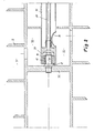
- the solid-bowl screw centrifuge equipped with a jacket 1 and a screw 2 is only shown with regard to the end face or storage located on the feed side of the suspension and in the inlet area into the separation space 3 formed between the casing 1 and the screw 2.
- the screw 2 is mounted at 4 on the casing, which in turn at 5 on a stationary component 6, which is viewed here as a bearing block.
- This embodiment shown in FIG. 1 is shown enlarged in the remaining figures only with regard to the inlet area area within the centrifuge.
- the inlet pipe 31 for the supply of the suspension is led from the stationary entry point of the suspension, not shown, in the right connection area of FIG. 1 as a stationary pipe into the inlet space 32 of the screw 2 and is supported with its end area 34 on a bolt 35, which in turn is supported engages in a bore 37 provided in the end boundary wall 36 of the inlet space 32 facing away from the inlet side.
- a slide bearing 12 with the two bearing shells 14 and 15 is arranged, so that there is a support between the bolt 35 and the end region 34 of the inlet pipe 31 against radial vibratory movements is.
- the suspension enters the long-shaped inlet pipe 31 in the direction of the arrow on the right and leaves it through the outlet opening 33, which leads into the inlet chamber 32 of the screw 2, from where the suspension in the usual way through openings in the screw hub into the separation chamber 3 reached. Due to the suspension given up through the inlet pipe 31 and its presence in the inlet chamber 32 of the screw 2, the slide bearing 12 is exposed to the suspension from both end faces.
- the suspension is used to form a hydrodynamic lubricating film for the plain bearing 12, on the other hand, its running surfaces are exposed to the stress emanating from the suspension.
- the two mutually sliding bearing shells 14 and 15 of the slide bearing 12 are made of a ceramic material, here in particular silicon carbide, so that abrasion and corrosion phenomena due to the lubricating effect of the suspension solids on the sliding surfaces does not occur or only occurs accordingly.
- the end region 34 of the inlet pipe 31 is held on a bolt 35 in a manner similar to that in the exemplary embodiment according to FIG. 1.
- a hexagon is provided which allows the bearing shell 14 to be pulled off the bolt.
- a special lubricant supply is provided via a line 39 in the event that the suspension supply is interrupted.
- the suspension entering the inlet space 32 through the outlet opening 33 forms the formation of the hydrodynamic lubricating film between the bearing shells 14 and 15 at the latest from the Ensures the end face facing away from the inlet, if the suspension supply is interrupted through line 39, a lubricant of whatever type is supplied which maintains the hydrodynamic lubricating film between the bearing shells 14 and 15.
- one or more temperature sensors can be provided, by means of which the special supply of lubricant to the plain bearing is automatically switched on when the temperature of the plain bearing rises.
- an emergency shutdown of the centrifuge can also be provided here.
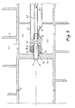
- the end region 34 of the inlet pipe 31 is supported via the slide bearing 12 or its bearing shells 14 and 15 in a similar manner as in the exemplary embodiment in FIG. 2, but the bolt on which the inner bearing shell 14 is, for example is held by a compensating body 16, formed as a hollow pin 38 which has an axially continuous bore.
- the opening of this through hole facing the inlet side is directed towards an inlet which is similar to that of the emergency lubricating fluid according to FIG. 2, but in the present exemplary embodiment according to FIG Feeds washing liquid into the interior of the screw, which adjoins the wall 36 of the inlet space 32 facing away from the suspension inlet.
- This space has small passage bores in the screw hub, through which the washing liquid enters the separating space of the centrifuge, specifically in its conical jacket area, in order to wash off solids.
- the compensating body 16 serves to compensate for temperature-related dimensional changes; it is designed to be elastically flexible in the radial direction. This ensures that when the temperature increases, the more stretching jacket of the end region 34 of the inlet pipe 31 or - with respect to FIG. 1 - the diameter increase of the bolt 35 stresses the ceramic bearing shell, which expands much less at this temperature, while the ceramic material is sensitive.
- the tubular compensating body has a corrugated jacket wall in itself, with the wave shape seen in the circumferential direction, or also with the wave shape seen in the axial direction, as indicated in the drawing.
- the radially outer bearing shell is - depending on the embodiment on the inner jacket wall of the end portion 34 of the inlet pipe 31 or the wall 36 or 43 ( Figure 5) of the screw body - fixed in that it is heated before inserting the bearing shell 15.
- the different coefficients of thermal expansion of the inlet pipe or the screw body wall - for example steel - on the one hand and the ceramic body on the other hand mean that the bearing shell is fixed in position by shrinking and thus compressed, whereas the ceramic material is insensitive.
- the supply of washing liquid is made with the aid of a washing liquid supply pipe 40 which is rigid in itself and serves as a connection between the slide bearing 12 and the end region 34 of the inlet pipe 31 insofar as the inner wall of the end region 34 of the inlet pipe 31 over radial webs 42 is supported on the outer jacket wall of the washing liquid supply pipe 40.
- This support takes place in the vicinity of the slide bearing 12, which is in the passage area of the washing liquid supply pipe 40 is arranged through the end wall 36 of the inlet space 32 facing away from the inlet side.
- the outer bearing shell 15 is supported on the inner wall of a corresponding hole in the partition, while the inner bearing shell 14 is supported on the outer jacket wall of the washing liquid supply pipe 40. Accordingly, the slide bearing 12 forms a seal between the space into which the washing liquid is introduced and the inlet space 32, into which the inlet pipe 31 opens at the end.
- the slide bearing 12 is arranged in the passage area of the inlet pipe 31 through that end partition 43 of the inlet space 32 of the screw 2 which faces the suspension inlet.
- the outer shell of the slide bearing 12 is supported on the inner wall of a corresponding bore in the end partition 43, while the inner bearing shell 14 engages on the outer circumferential surface of the inlet pipe 31.
Landscapes
- Centrifugal Separators (AREA)
- Sliding-Contact Bearings (AREA)
Applications Claiming Priority (2)
| Application Number | Priority Date | Filing Date | Title |
|---|---|---|---|
| DE3816210 | 1988-05-11 | ||
| DE19883816210 DE3816210A1 (de) | 1986-11-12 | 1988-05-11 | Vollmantel-schneckenzentrifuge |
Publications (3)
| Publication Number | Publication Date |
|---|---|
| EP0341433A2 true EP0341433A2 (fr) | 1989-11-15 |
| EP0341433A3 EP0341433A3 (en) | 1990-04-25 |
| EP0341433B1 EP0341433B1 (fr) | 1993-08-04 |
Family
ID=6354231
Family Applications (1)
| Application Number | Title | Priority Date | Filing Date |
|---|---|---|---|
| EP89106271A Expired - Lifetime EP0341433B1 (fr) | 1988-05-11 | 1989-04-10 | Centrifugeuse à vis à bol plein |
Country Status (4)
| Country | Link |
|---|---|
| US (1) | US4957475A (fr) |
| EP (1) | EP0341433B1 (fr) |
| JP (1) | JPH01317560A (fr) |
| DK (1) | DK228589A (fr) |
Cited By (4)
| Publication number | Priority date | Publication date | Assignee | Title |
|---|---|---|---|---|
| EP0438767A3 (en) * | 1990-01-25 | 1991-12-04 | Basf Aktiengesellschaft | Process for the separation of riboflavin from a fermentation suspension |
| US20150238977A1 (en) * | 2014-02-26 | 2015-08-27 | Ferrum Ag | Centrifuge and method of loading a centrifuge |
| WO2019007886A1 (fr) * | 2017-07-06 | 2019-01-10 | Gea Mechanical Equipment Gmbh | Centrifugeuse à vis sans fin et à bol plein |
| EP4295957A1 (fr) * | 2022-06-24 | 2023-12-27 | Hermeler, Jürgen | Centrifugeuse décanteuse |
Families Citing this family (10)
| Publication number | Priority date | Publication date | Assignee | Title |
|---|---|---|---|---|
| US5156751A (en) * | 1991-03-29 | 1992-10-20 | Miller Neal J | Three stage centrifuge and method for separating water and solids from petroleum products |
| US5403486A (en) * | 1991-12-31 | 1995-04-04 | Baker Hughes Incorporated | Accelerator system in a centrifuge |
| US5364335A (en) * | 1993-12-07 | 1994-11-15 | Dorr-Oliver Incorporated | Disc-decanter centrifuge |
| DK0868215T3 (da) * | 1995-12-01 | 2002-05-06 | Baker Hughes Inc | Fremgangsmåde og apparat til styring og overvågning af en centrifuge med kontinuerlig tilførsel |
| US8328877B2 (en) | 2002-03-19 | 2012-12-11 | Boston Scientific Scimed, Inc. | Stent retention element and related methods |
| DK200970026A (en) * | 2009-06-12 | 2010-12-13 | Alfa Laval Corp Ab | A centrifugal separator |
| US8651240B1 (en) | 2012-12-24 | 2014-02-18 | United Technologies Corporation | Pressurized reserve lubrication system for a gas turbine engine |
| DE102012018241B4 (de) * | 2012-09-17 | 2014-12-18 | Gea Mechanical Equipment Gmbh | Separator |
| JP2017189752A (ja) * | 2016-04-15 | 2017-10-19 | 日本フローサーブ株式会社 | 立型固液分離装置 |
| DE102018119279A1 (de) * | 2018-08-08 | 2020-02-13 | Gea Mechanical Equipment Gmbh | Vollmantel-Schneckenzentrifuge |
Family Cites Families (14)
| Publication number | Priority date | Publication date | Assignee | Title |
|---|---|---|---|---|
| FR1251684A (fr) * | 1960-03-18 | 1961-01-20 | Krupp Dolberg Gmbh | Machine centrifuge à vis sans fin |
| US3172851A (en) * | 1962-08-31 | 1965-03-09 | Centrifuging liquid-solids mixtures | |
| US3326457A (en) * | 1964-02-14 | 1967-06-20 | United States Steel Corp | Method and apparatus for steamassisted centrifugal dewatering |
| US3379368A (en) * | 1965-12-06 | 1968-04-23 | Gilreath Hydraulies Inc | Centrifugal separator |
| US3568919A (en) * | 1968-01-10 | 1971-03-09 | Titan Separator As | Screw centrifuge |
| US3575709A (en) * | 1968-08-20 | 1971-04-20 | Bird Machine Co | Method of cleaning sugar crystals |
| DE2160493A1 (de) * | 1971-12-07 | 1973-06-14 | Erich Rosenthal | Verteilerring fuer pneumatische medien zum schmieren und kuehlen von rotierenden reibungsflaechen |
| US3854658A (en) * | 1973-05-07 | 1974-12-17 | Dorr Oliver Inc | Solid bowl conveyer type centrifuge |
| US4334647A (en) * | 1980-12-03 | 1982-06-15 | Bird Machine Company, Inc. | Centrifuges |
| DE3326310C2 (de) * | 1983-07-21 | 1986-02-20 | Westfalia Separator Ag, 4740 Oelde | Vollmantelzentrifuge mit einer Förderschnecke |
| AU579834B2 (en) * | 1983-09-30 | 1988-12-15 | Ebara Corporation | Combination of slide members |
| DE3509572C1 (de) * | 1985-03-16 | 1986-07-10 | Feldmühle AG, 4000 Düsseldorf | Mit keramischen Werkstoffkomponenten beschichtetes Gleitelement und seine Verwendung |
| DE3638652A1 (de) * | 1986-11-12 | 1988-06-01 | Flottweg Bird Mach Gmbh | Vollmantel-schneckenzentrifuge |
| DE8706954U1 (de) * | 1987-05-14 | 1987-07-02 | Hermetic-Pumpen Gmbh, 7803 Gundelfingen | Gleitlager für Pumpen |
-
1989
- 1989-04-10 EP EP89106271A patent/EP0341433B1/fr not_active Expired - Lifetime
- 1989-05-04 US US07/347,758 patent/US4957475A/en not_active Expired - Fee Related
- 1989-05-10 JP JP1118486A patent/JPH01317560A/ja active Pending
- 1989-05-10 DK DK228589A patent/DK228589A/da not_active Application Discontinuation
Cited By (8)
| Publication number | Priority date | Publication date | Assignee | Title |
|---|---|---|---|---|
| EP0438767A3 (en) * | 1990-01-25 | 1991-12-04 | Basf Aktiengesellschaft | Process for the separation of riboflavin from a fermentation suspension |
| US5169759A (en) * | 1990-01-25 | 1992-12-08 | Basf Aktiengesellschaft | Removal of riboflavin from fermentation suspensions |
| US20150238977A1 (en) * | 2014-02-26 | 2015-08-27 | Ferrum Ag | Centrifuge and method of loading a centrifuge |
| EP2913112A1 (fr) * | 2014-02-26 | 2015-09-02 | Ferrum AG | Centrifugeuse et procédé de chargement d'une centrifugeuse |
| US10639647B2 (en) * | 2014-02-26 | 2020-05-05 | Ferrum Ag | Centrifuge with a feed device comprising a feed direction control and method of loading a centrifuge with a feed device comprising a feed direction control |
| WO2019007886A1 (fr) * | 2017-07-06 | 2019-01-10 | Gea Mechanical Equipment Gmbh | Centrifugeuse à vis sans fin et à bol plein |
| EP4295957A1 (fr) * | 2022-06-24 | 2023-12-27 | Hermeler, Jürgen | Centrifugeuse décanteuse |
| WO2023247183A1 (fr) * | 2022-06-24 | 2023-12-28 | Hermeler Prof Dr Juergen | Centrifugeuse de décantation |
Also Published As
| Publication number | Publication date |
|---|---|
| JPH01317560A (ja) | 1989-12-22 |
| EP0341433B1 (fr) | 1993-08-04 |
| US4957475A (en) | 1990-09-18 |
| DK228589A (da) | 1989-11-12 |
| EP0341433A3 (en) | 1990-04-25 |
| DK228589D0 (da) | 1989-05-10 |
Similar Documents
| Publication | Publication Date | Title |
|---|---|---|
| EP0341433B1 (fr) | Centrifugeuse à vis à bol plein | |
| DE3619489C2 (fr) | ||
| DE3106318C1 (de) | Abdichtungsanordnung mit Kuehleinrichtung | |
| DE60212451T2 (de) | Aussenseitig befestigter spiraladapter | |
| DE10229406A1 (de) | Vorrichtung zum kontinuierlichen Filtern von Materialgemischen | |
| AT523264B1 (de) | Verfahren zur Herstellung eines Siebkörpers sowie Sieb | |
| DE8816668U1 (de) | Kraftbetätigtes Spannfutter | |
| EA036223B1 (ru) | Устройство для обезвоживания текучего или сыпучего сырьевого материала | |
| US3980013A (en) | Split worm for screw press | |
| DE1782548B2 (de) | Vollmantel-Schneckenzentrifuge | |
| DE202021106173U1 (de) | Mechanische Dichtungseinrichtung zum Abdichten von Flüssigkeit | |
| DE1817573A1 (de) | Schneckenzentrifuge | |
| DE19847103C1 (de) | Maschine zum kontinuierlichen Bearbeiten von fließfähigen Materialien | |
| DE1425968A1 (de) | Fluidlager | |
| EP0857258B1 (fr) | Dispositif pour raccorder la conduite de refroidissement d'une piece tournante | |
| DE3129403C2 (de) | Vorrichtung für die Kühlmittelzufuhr zu mit Kühlmittelkanälen versehenen, rotierenden Schneidwerkzeugen für die spanende Metallverarbeitung, insbesondere Bohrwerkzeugen. | |
| DE10132688A1 (de) | Innenlager für Schneckenmaschinen | |
| EP0731284B1 (fr) | Collier de verrouillage pour éléments cylindriques | |
| DE4326150C2 (de) | Vorrichtung zur axialen Festlegung von Bauteilen | |
| DE3638652C2 (fr) | ||
| DE2520667C2 (de) | Schraubenspindelpumpe | |
| DE102016115039A1 (de) | Werkzeugaufnahme | |
| DE19621773A1 (de) | Außendruckluftlagerspindel | |
| DE3816210A1 (de) | Vollmantel-schneckenzentrifuge | |
| DE10217181B4 (de) | Vorrichtung zur Begrenzung von Leckströmen an gelagerten Wellendurchführungen |
Legal Events
| Date | Code | Title | Description |
|---|---|---|---|
| PUAI | Public reference made under article 153(3) epc to a published international application that has entered the european phase |
Free format text: ORIGINAL CODE: 0009012 |
|
| AK | Designated contracting states |
Kind code of ref document: A2 Designated state(s): FR GB IT |
|
| PUAL | Search report despatched |
Free format text: ORIGINAL CODE: 0009013 |
|
| AK | Designated contracting states |
Kind code of ref document: A3 Designated state(s): FR GB IT |
|
| 17P | Request for examination filed |
Effective date: 19900530 |
|
| 17Q | First examination report despatched |
Effective date: 19910722 |
|
| ITF | It: translation for a ep patent filed | ||
| GRAA | (expected) grant |
Free format text: ORIGINAL CODE: 0009210 |
|
| AK | Designated contracting states |
Kind code of ref document: B1 Designated state(s): FR GB IT |
|
| ET | Fr: translation filed | ||
| GBT | Gb: translation of ep patent filed (gb section 77(6)(a)/1977) |
Effective date: 19931011 |
|
| ITTA | It: last paid annual fee | ||
| PLBE | No opposition filed within time limit |
Free format text: ORIGINAL CODE: 0009261 |
|
| STAA | Information on the status of an ep patent application or granted ep patent |
Free format text: STATUS: NO OPPOSITION FILED WITHIN TIME LIMIT |
|
| 26N | No opposition filed | ||
| PGFP | Annual fee paid to national office [announced via postgrant information from national office to epo] |
Ref country code: GB Payment date: 19980402 Year of fee payment: 10 |
|
| PG25 | Lapsed in a contracting state [announced via postgrant information from national office to epo] |
Ref country code: GB Free format text: LAPSE BECAUSE OF NON-PAYMENT OF DUE FEES Effective date: 19990410 |
|
| GBPC | Gb: european patent ceased through non-payment of renewal fee |
Effective date: 19990410 |
|
| PGFP | Annual fee paid to national office [announced via postgrant information from national office to epo] |
Ref country code: FR Payment date: 20000428 Year of fee payment: 12 |
|
| PG25 | Lapsed in a contracting state [announced via postgrant information from national office to epo] |
Ref country code: FR Free format text: THE PATENT HAS BEEN ANNULLED BY A DECISION OF A NATIONAL AUTHORITY Effective date: 20010430 |
|
| REG | Reference to a national code |
Ref country code: FR Ref legal event code: ST |
|
| PG25 | Lapsed in a contracting state [announced via postgrant information from national office to epo] |
Ref country code: IT Free format text: LAPSE BECAUSE OF NON-PAYMENT OF DUE FEES;WARNING: LAPSES OF ITALIAN PATENTS WITH EFFECTIVE DATE BEFORE 2007 MAY HAVE OCCURRED AT ANY TIME BEFORE 2007. THE CORRECT EFFECTIVE DATE MAY BE DIFFERENT FROM THE ONE RECORDED. Effective date: 20050410 |