EP0341433A2 - Solid bowl screw conveyor centrifuge - Google Patents
Solid bowl screw conveyor centrifuge Download PDFInfo
- Publication number
- EP0341433A2 EP0341433A2 EP89106271A EP89106271A EP0341433A2 EP 0341433 A2 EP0341433 A2 EP 0341433A2 EP 89106271 A EP89106271 A EP 89106271A EP 89106271 A EP89106271 A EP 89106271A EP 0341433 A2 EP0341433 A2 EP 0341433A2
- Authority
- EP
- European Patent Office
- Prior art keywords
- centrifuge
- bearing
- slide bearing
- screw
- inlet pipe
- Prior art date
- Legal status (The legal status is an assumption and is not a legal conclusion. Google has not performed a legal analysis and makes no representation as to the accuracy of the status listed.)
- Granted
Links
Images


Classifications
-
- B—PERFORMING OPERATIONS; TRANSPORTING
- B04—CENTRIFUGAL APPARATUS OR MACHINES FOR CARRYING-OUT PHYSICAL OR CHEMICAL PROCESSES
- B04B—CENTRIFUGES
- B04B1/00—Centrifuges with rotary bowls provided with solid jackets for separating predominantly liquid mixtures with or without solid particles
- B04B1/20—Centrifuges with rotary bowls provided with solid jackets for separating predominantly liquid mixtures with or without solid particles discharging solid particles from the bowl by a conveying screw coaxial with the bowl axis and rotating relatively to the bowl
-
- B—PERFORMING OPERATIONS; TRANSPORTING
- B04—CENTRIFUGAL APPARATUS OR MACHINES FOR CARRYING-OUT PHYSICAL OR CHEMICAL PROCESSES
- B04B—CENTRIFUGES
- B04B11/00—Feeding, charging, or discharging bowls
- B04B11/06—Arrangement of distributors or collectors in centrifuges
-
- B—PERFORMING OPERATIONS; TRANSPORTING
- B04—CENTRIFUGAL APPARATUS OR MACHINES FOR CARRYING-OUT PHYSICAL OR CHEMICAL PROCESSES
- B04B—CENTRIFUGES
- B04B9/00—Drives specially designed for centrifuges; Arrangement or disposition of transmission gearing; Suspending or balancing rotary bowls
- B04B9/12—Suspending rotary bowls ; Bearings; Packings for bearings
-
- B—PERFORMING OPERATIONS; TRANSPORTING
- B04—CENTRIFUGAL APPARATUS OR MACHINES FOR CARRYING-OUT PHYSICAL OR CHEMICAL PROCESSES
- B04B—CENTRIFUGES
- B04B1/00—Centrifuges with rotary bowls provided with solid jackets for separating predominantly liquid mixtures with or without solid particles
- B04B1/20—Centrifuges with rotary bowls provided with solid jackets for separating predominantly liquid mixtures with or without solid particles discharging solid particles from the bowl by a conveying screw coaxial with the bowl axis and rotating relatively to the bowl
- B04B2001/2033—Centrifuges with rotary bowls provided with solid jackets for separating predominantly liquid mixtures with or without solid particles discharging solid particles from the bowl by a conveying screw coaxial with the bowl axis and rotating relatively to the bowl with feed accelerator inside the conveying screw
Definitions
- the invention relates to a solid bowl screw centrifuge with the features of claim 1.
- suspensions are separated into a solid and at least one liquid phase under centrifugal force.
- Such suspensions can consist of a variety of compositions; they can contain chemically aggressive substances and / or contain particles that cause high abrasion, such as sand. It is therefore endeavored, in the course of feeding such suspensions, to use lines which are as continuous as possible to the separating space of the centrifuge or a distributor space which opens into the separating space within the screw hub. This often results in long pipe lengths, such as problems with regard to their mounting or their risk of causing strong radial vibrations. This is especially the case with centrifuges of the type in question here, which operate in the so-called counterflow principle, i.e.
- the object of the invention is to supply the suspension as far as possible up to the point of entry into the separating chamber of the centrifuge via a fixed inlet pipe, even if the inlet is in the separating chamber seen very far from the feed end of the centrifuge jacket in the longitudinal center area and above the centrifuge, as is the case with countercurrent centrifuges, without the long, fixed inlet pipe can cause malfunctions due to large radial vibrations and without time and costly repair and / or maintenance work.
- the correspondingly long inlet pipe protruding into an inlet space of the screw which opens directly into the separating space of the centrifuge through radial openings, is formed on its end region facing the inlet space with the aid of a slide bearing on an integral part of the screw body or on the screw body Screw part supported, whereby interfering radial vibrations of the inlet pipe are intercepted.
- the plain bearing which is arranged correspondingly far inside the screw of the centrifuge, is designed such that the two bearing shells in the sliding engagement area consist of a ceramic material.
- the two ceramic bearing shells are acted upon by the suspension, which, however, does not pose any problems with regard to wear and / or maintenance, because such ceramic materials are extremely resistant to abrasion and corrosion, so that such a bearing with a ceramic bearing in the sliding attack area is also available can be used safely and permanently for suspensions with appropriate abrasion and corrosion properties.
- Tolerate such plain bearings high speeds and also withstand a pressure build-up, as can occur in a certain bearing arrangement from the separation space.
- such ceramic materials are highly heat-resistant and tolerate strong temperature changes.
- Ceramic materials in question there are a number of ceramic materials in question, this or that ceramic material will be preferred depending on the application or suspension, such as Si3N4, Al2O3, MgO, ZrO2; however, oxide-free ceramics are preferably used, and preferably SiC, in a sintered form, so that pure silicon carbide is contained without a free silicon content.
- This can be done in particular by the fact that the slide bearing is connected to the interior of the inlet pipe and is lubricated by the centrifugal medium introduced into the separating space of the centrifuge via the inlet pipe.
- a replacement liquid for lubricating the slide bearing can also be provided, which is automatically supplied when the addition of the centrifugal medium is interrupted.
- a separate line can be provided for the supply of the lubricant to the slide bearing.
- the temperature of the slide bearing can be sensed with the aid of temperature sensors, so that when the temperature of the slide bearing rises above a certain value, the lubricant supply to the slide bearing is automatically switched on or the centrifuge is switched off.
- a cavity for the introduction of washing liquid can be provided in the screw body, the sliding bearing also being used as a seal in the transition area of a stationary supply line for the washing liquid to the rotating screw body is.
- the inlet pipe in that a washing liquid supply pipe is supported on the bearing on the worm hub body, the inlet pipe can be supported on the washing liquid supply pipe so that the end region of the inlet pipe is supported indirectly on the sliding bearing on the worm hub.
- care can be taken to ensure that an inspection of this ceramic bearing located inside the screw, ie in the area of the screw's inlet space, can be carried out in a simple manner without dismantling the centrifuge.
- the ceramic plain bearing slides over a lubrication film fed by the applied suspension, in a preferred embodiment it is ensured that the hydrodynamic lubrication film is maintained by another lubricant if the suspension is not supplied.
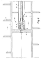
- the solid-bowl screw centrifuge equipped with a jacket 1 and a screw 2 is only shown with regard to the end face or storage located on the feed side of the suspension and in the inlet area into the separation space 3 formed between the casing 1 and the screw 2.
- the screw 2 is mounted at 4 on the casing, which in turn at 5 on a stationary component 6, which is viewed here as a bearing block.
- This embodiment shown in FIG. 1 is shown enlarged in the remaining figures only with regard to the inlet area area within the centrifuge.
- the inlet pipe 31 for the supply of the suspension is led from the stationary entry point of the suspension, not shown, in the right connection area of FIG. 1 as a stationary pipe into the inlet space 32 of the screw 2 and is supported with its end area 34 on a bolt 35, which in turn is supported engages in a bore 37 provided in the end boundary wall 36 of the inlet space 32 facing away from the inlet side.
- a slide bearing 12 with the two bearing shells 14 and 15 is arranged, so that there is a support between the bolt 35 and the end region 34 of the inlet pipe 31 against radial vibratory movements is.
- the suspension enters the long-shaped inlet pipe 31 in the direction of the arrow on the right and leaves it through the outlet opening 33, which leads into the inlet chamber 32 of the screw 2, from where the suspension in the usual way through openings in the screw hub into the separation chamber 3 reached. Due to the suspension given up through the inlet pipe 31 and its presence in the inlet chamber 32 of the screw 2, the slide bearing 12 is exposed to the suspension from both end faces.
- the suspension is used to form a hydrodynamic lubricating film for the plain bearing 12, on the other hand, its running surfaces are exposed to the stress emanating from the suspension.
- the two mutually sliding bearing shells 14 and 15 of the slide bearing 12 are made of a ceramic material, here in particular silicon carbide, so that abrasion and corrosion phenomena due to the lubricating effect of the suspension solids on the sliding surfaces does not occur or only occurs accordingly.
- the end region 34 of the inlet pipe 31 is held on a bolt 35 in a manner similar to that in the exemplary embodiment according to FIG. 1.
- a hexagon is provided which allows the bearing shell 14 to be pulled off the bolt.
- a special lubricant supply is provided via a line 39 in the event that the suspension supply is interrupted.
- the suspension entering the inlet space 32 through the outlet opening 33 forms the formation of the hydrodynamic lubricating film between the bearing shells 14 and 15 at the latest from the Ensures the end face facing away from the inlet, if the suspension supply is interrupted through line 39, a lubricant of whatever type is supplied which maintains the hydrodynamic lubricating film between the bearing shells 14 and 15.
- one or more temperature sensors can be provided, by means of which the special supply of lubricant to the plain bearing is automatically switched on when the temperature of the plain bearing rises.
- an emergency shutdown of the centrifuge can also be provided here.
- the end region 34 of the inlet pipe 31 is supported via the slide bearing 12 or its bearing shells 14 and 15 in a similar manner as in the exemplary embodiment in FIG. 2, but the bolt on which the inner bearing shell 14 is, for example is held by a compensating body 16, formed as a hollow pin 38 which has an axially continuous bore.
- the opening of this through hole facing the inlet side is directed towards an inlet which is similar to that of the emergency lubricating fluid according to FIG. 2, but in the present exemplary embodiment according to FIG Feeds washing liquid into the interior of the screw, which adjoins the wall 36 of the inlet space 32 facing away from the suspension inlet.
- This space has small passage bores in the screw hub, through which the washing liquid enters the separating space of the centrifuge, specifically in its conical jacket area, in order to wash off solids.
- the compensating body 16 serves to compensate for temperature-related dimensional changes; it is designed to be elastically flexible in the radial direction. This ensures that when the temperature increases, the more stretching jacket of the end region 34 of the inlet pipe 31 or - with respect to FIG. 1 - the diameter increase of the bolt 35 stresses the ceramic bearing shell, which expands much less at this temperature, while the ceramic material is sensitive.
- the tubular compensating body has a corrugated jacket wall in itself, with the wave shape seen in the circumferential direction, or also with the wave shape seen in the axial direction, as indicated in the drawing.
- the radially outer bearing shell is - depending on the embodiment on the inner jacket wall of the end portion 34 of the inlet pipe 31 or the wall 36 or 43 ( Figure 5) of the screw body - fixed in that it is heated before inserting the bearing shell 15.
- the different coefficients of thermal expansion of the inlet pipe or the screw body wall - for example steel - on the one hand and the ceramic body on the other hand mean that the bearing shell is fixed in position by shrinking and thus compressed, whereas the ceramic material is insensitive.
- the supply of washing liquid is made with the aid of a washing liquid supply pipe 40 which is rigid in itself and serves as a connection between the slide bearing 12 and the end region 34 of the inlet pipe 31 insofar as the inner wall of the end region 34 of the inlet pipe 31 over radial webs 42 is supported on the outer jacket wall of the washing liquid supply pipe 40.
- This support takes place in the vicinity of the slide bearing 12, which is in the passage area of the washing liquid supply pipe 40 is arranged through the end wall 36 of the inlet space 32 facing away from the inlet side.
- the outer bearing shell 15 is supported on the inner wall of a corresponding hole in the partition, while the inner bearing shell 14 is supported on the outer jacket wall of the washing liquid supply pipe 40. Accordingly, the slide bearing 12 forms a seal between the space into which the washing liquid is introduced and the inlet space 32, into which the inlet pipe 31 opens at the end.
- the slide bearing 12 is arranged in the passage area of the inlet pipe 31 through that end partition 43 of the inlet space 32 of the screw 2 which faces the suspension inlet.
- the outer shell of the slide bearing 12 is supported on the inner wall of a corresponding bore in the end partition 43, while the inner bearing shell 14 engages on the outer circumferential surface of the inlet pipe 31.
Landscapes
- Centrifugal Separators (AREA)
- Sliding-Contact Bearings (AREA)
Abstract
Vollmantel-Schneckenzentrifuge für die Trennung eines Suspension, für deren Zuführung von einer ortsfesten Eingabestelle außerhalb der Zentrifuge in den zwischen der Schnecke (2) und dem Mantel (1) gebildeten Trennraum (3) der Zentrifuge ein ortsfest gehaltenes Einlaufrohr (31) vorgesehen ist, das für eine Verhinderung fliehkraftbedingeter Verstopfungen, radialschwingungsbedingter Störungen und wartungsarmer Betriebsweise derart ausgestaltet ist, daß sich dieses Einlaufrohr bis in einen Einlaufraum (32) der Schnecke (2) erstreckt und in seinem dortigen Endbereich (34) an einem schneckenfesten Teil (35, 36) über ein Gleitlager (12) abstützt, dessen beide Lagerschalen (14, 15) im Gleitangriffsbereich aus einem keramischen Werkstoff bestehen.Solid-bowl screw centrifuge for the separation of a suspension, for the supply of which from a stationary entry point outside the centrifuge into the separation space (3) of the centrifuge formed between the screw (2) and the casing (1), a stationary inlet pipe (31) is provided, which is designed to prevent centrifugal blockages, radial vibration-related malfunctions and low-maintenance operation in such a way that this inlet pipe extends into an inlet space (32) of the screw (2) and in its end region (34) there on a screw-fixed part (35, 36) is supported by a slide bearing (12), the two bearing shells (14, 15) of which are made of a ceramic material in the sliding engagement area.
Description
Die Erfindung bezieht sich auf eine Vollmantel-Schneckenzentrifuge mit den Merkmalen des Anspruches 1.The invention relates to a solid bowl screw centrifuge with the features of claim 1.
In solchen Zentrifugen werden unter Fliehkraft Suspensionen in eine feste und wenigstens eine flüssige Phase getrennt. Solche Suspensionen können aus vielerlei Zusammensetzungen bestehen; sie können chemisch agressive Stoffe enthalten und/oder hohen Abrieb verursachende Partikel, wie beispielsweise Sand, enthalten. Man ist daher bestrebt, im Rahmen der Zuführung solcher Suspensionen möglichst durchgehende Leitungen bis hin zum Trennraum der Zentrifuge bzw. einen in den Trennraum mündenden Verteilerraum innerhalb der Schneckennabe zu verwenden. Dabei treten vielfach große Rohrlängen auf, wie hinsichtlich ihrer Halterung bzw. ihrer Gefahr, starke radiale Schwingungen auszuführen, Probleme bereiten. Dies ist vor allem bei Zentrifugen der hier in Rede stehenden Art der Fall, die im sogenannten Gegenstromprinzip arbeiten, d.h. bei denen der Suspensionseinlauf in den Trennraum weit im Inneren der Zentrifuge vorgesehen ist. Eine Lagerung eines solchen langen ortsfestes Einlaufrohres in dessen Endbereich innerhalb der Schneckennabe könnte zwar diese Problematik beseitigen, doch ist ein solches Lager innerhalb der Schneckennabe stärker der Verschmutzung ausgesetzt und für Wartungsarbeiten nur sehr schwer zugänglich.In such centrifuges, suspensions are separated into a solid and at least one liquid phase under centrifugal force. Such suspensions can consist of a variety of compositions; they can contain chemically aggressive substances and / or contain particles that cause high abrasion, such as sand. It is therefore endeavored, in the course of feeding such suspensions, to use lines which are as continuous as possible to the separating space of the centrifuge or a distributor space which opens into the separating space within the screw hub. This often results in long pipe lengths, such as problems with regard to their mounting or their risk of causing strong radial vibrations. This is especially the case with centrifuges of the type in question here, which operate in the so-called counterflow principle, i.e. in which the suspension inlet into the separation chamber is provided far inside the centrifuge. Storing such a long, stationary inlet pipe in its end region within the worm hub could eliminate this problem, but such a bearing inside the worm hub is more exposed to contamination and is very difficult to access for maintenance work.
Der Erfindung liegt die Aufgabe zugrunde, die Suspension möglichst weitgehend bis zum Eintritt in den Trennraum der Zentrifuge über ein feststehendes Einlaufrohr zuzuführen, auch wenn sich der Zulauf in den Trennraum sehr weit von der Zuführstirnseite des Zentrifugenmantels aus gesehen im Längsmittelbereich und darüber der Zentrifuge befindet, wie dies bei Gegenstrom-Zentrifugen der Fall ist, ohne daß das derart lang ausgebildete, feststehende Einlaufrohr Betriebsstörungen durch entsprechend große radiale Schwingungen verursachen kann und ohne daß zeit- und kostenintensive Reparatur und/oder Wartungsarbeiten auftreten.The object of the invention is to supply the suspension as far as possible up to the point of entry into the separating chamber of the centrifuge via a fixed inlet pipe, even if the inlet is in the separating chamber seen very far from the feed end of the centrifuge jacket in the longitudinal center area and above the centrifuge, as is the case with countercurrent centrifuges, without the long, fixed inlet pipe can cause malfunctions due to large radial vibrations and without time and costly repair and / or maintenance work.
Ausgehend von einer Vollmantel-Schneckenzentrifuge mit den Merkmalen des Oberbegriffes des Anspruches 1 wird diese Aufgabe erfindungsgemäß durch dessen kennzeichnende Merkmale gelöst.Starting from a solid bowl screw centrifuge with the features of the preamble of claim 1, this object is achieved according to the invention by its characterizing features.
Dazu wird das bis in einen Einlaufraum der Schnecke, der durch radiale Öffnungen unmittelbar in den Trennraum der Zentrifuge mündet, vorstehende, entsprechend lang ausgebildete Einlaufrohr an seinem dem Einlaufraum zugewandten Endbereich mit Hilfe eines Gleitlagers an einem an dem Schneckenkörper fest bzw. mit diesem einstückig ausgebildeten Schneckenteil abgestützt, wodurch störende radiale Schwingungen des Einlaufrohres abgefangen werden. Dabei ist das entsprechend weit im Inneren der Schnecke der Zentrifuge angeordnete Gleitlager derart ausgebildet, daß die beiden Lagerschalen im Gleitangriffsbereich aus einem keramischen Werkstoff bestehen. Im Gleitangriffsbereich werden die beiden keramischen Lagerschalen durch die Suspension beaufschlagt, was jedoch hinsichtlich des Verschleißes und/oder der Wartung keine Probleme bereitet, weil solche keramischen Werkstoffe äußerst widerstandsfähig gegen Abrasionen und Korrisionen sind, so daß sich ein solches mit im Gleitangriffsbereich keramisch ausgebildeten Gleitlager auch bei Suspensionen entsprechender Abriebs- und Korrisionseigenschaften sicher und dauerhaft einsetzen läßt. Solche Gleitlager vertragen hohe Drehzahlen und halten auch einem Druckaufbau stand, wie er vom Trennraum her bei bestimmter Lageranordnung auftreten kann. Darüber hinaus sind solche keramischen Werkstoffe hoch hitzebeständig und vertragen starke Temperaturwechsel.For this purpose, the correspondingly long inlet pipe protruding into an inlet space of the screw, which opens directly into the separating space of the centrifuge through radial openings, is formed on its end region facing the inlet space with the aid of a slide bearing on an integral part of the screw body or on the screw body Screw part supported, whereby interfering radial vibrations of the inlet pipe are intercepted. The plain bearing, which is arranged correspondingly far inside the screw of the centrifuge, is designed such that the two bearing shells in the sliding engagement area consist of a ceramic material. In the sliding attack area, the two ceramic bearing shells are acted upon by the suspension, which, however, does not pose any problems with regard to wear and / or maintenance, because such ceramic materials are extremely resistant to abrasion and corrosion, so that such a bearing with a ceramic bearing in the sliding attack area is also available can be used safely and permanently for suspensions with appropriate abrasion and corrosion properties. Tolerate such plain bearings high speeds and also withstand a pressure build-up, as can occur in a certain bearing arrangement from the separation space. In addition, such ceramic materials are highly heat-resistant and tolerate strong temperature changes.
Es kommt eine Reihe von Keramik-Materialien in Frage, wobei dieser oder jener Keramik-Werkstoff je nach Einsatzzweck bzw. Suspension zu bevorzugen sein wird, so beispielsweise auch Si₃N₄, Al₂O₃, MgO, ZrO₂; vorzugsweise werden jedoch oxidfreie Keramiken verwendet und bevorzugt SiC, und zwar in gesinterter Form, so daß man reines Siliziumkarbit ohne freien Siliziumanteil enthält.There are a number of ceramic materials in question, this or that ceramic material will be preferred depending on the application or suspension, such as Si₃N₄, Al₂O₃, MgO, ZrO₂; however, oxide-free ceramics are preferably used, and preferably SiC, in a sintered form, so that pure silicon carbide is contained without a free silicon content.
Grundsätzlich ist es möglich, die radial außen angeordnete Lagerschale des Gleitlagers an einer der Stirnbegrenzungswandungen des Einlaufraumes der Schneckennabe festzulegen, während die radial innen angeordnete Lagerschale des Gleitlagers an der Außenwandung des feststehenden bzw. ortsfest gehaltenen Einlaufrohres festgelegt ist. Eine andere Möglichkeit besteht darin, die radial innen angeordnete Lagerschale des Gleitlagers auf einem an der Stirnbegrenzungswandung des Einlaufraumes festgelegten Bolzen, auch Hohlbolzen, zu halten und die radial außenliegende Lagerschale des Gleitlagers am Endrand des Endbereiches des ortsfesten Einlaufrohres oder einer Erweiterung dieses Endbereiches festzulegen. Der Endbereich des Einlaufrohres kann auch mittelbar, beispielsweise über ein weiteres konzentrisch innenliegendes Rohr an einer Trennwand des Schneckenkörpers abgestützt sein.Basically, it is possible to fix the radially outer bearing shell of the slide bearing on one of the end boundary walls of the inlet space of the worm hub, while the radially inner bearing shell of the sliding bearing is fixed on the outer wall of the fixed or stationary inlet pipe. Another possibility is to hold the bearing shell of the plain bearing arranged radially on the inside on a bolt, also hollow bolt, fixed to the end wall of the inlet space and to fix the radially outer bearing shell of the plain bearing at the end edge of the end region of the stationary inlet pipe or an extension of this end region. The end region of the inlet pipe can also be supported indirectly, for example via a further concentrically inner pipe, on a partition of the screw body.
In weiterhin bevorzugter Ausführung ist dafür Sorge getragen, daß sich zwischen den aneinander gleitenden Lagerschalenflächen des Gleitlagers durch Anwesenheit eines flüssigen Mediums ein hydrodynamischer Schmierfilm aufbaut. Dies kann insbesondere dadurch geschehen, daß das Gleitlager mit dem Innenraum des Einlaufrohres in Verbindung steht und durch das über das Einlaufrohr in den Trennraum der Zentrifuge eingeleitete Schleudermedium geschmiert wird. Es kann aber auch eine Ersatzflüssigkeit zur Schmierung des Gleitlagers vorgesehen sein, die bei Unterbrechung der Zugabe des Schleudermediums selbsttätig zugeführt wird. Insbesondere kann für die Zuführung der Schmierflüssigkeit zum Gleitlager eine separate Leitung vorgesehen werden. Weiterhin kann die Temperatur des Gleitlagers mit Hilfe von Temperaturfühlern abgetastet werden, so daß bei Anstieg der Temperatur des Gleitlagers über einen bestimmten Wert die Schmiermittelversorgung des Gleitlagers selbsttätig eingeschaltet oder die Zentrifuge abgeschaltet wird.In a further preferred embodiment, care is taken to ensure that a hydrodynamic lubricating film is present between the sliding bearing shell surfaces of the slide bearing due to the presence of a liquid medium builds up. This can be done in particular by the fact that the slide bearing is connected to the interior of the inlet pipe and is lubricated by the centrifugal medium introduced into the separating space of the centrifuge via the inlet pipe. However, a replacement liquid for lubricating the slide bearing can also be provided, which is automatically supplied when the addition of the centrifugal medium is interrupted. In particular, a separate line can be provided for the supply of the lubricant to the slide bearing. Furthermore, the temperature of the slide bearing can be sensed with the aid of temperature sensors, so that when the temperature of the slide bearing rises above a certain value, the lubricant supply to the slide bearing is automatically switched on or the centrifuge is switched off.
In einem konischen Bereich der Zentrifuge, der der Abführung des Feststoffes aus dem Sumpf des Trennraumes dient, kann im Schneckenkörper ein Hohlraum zur Einleitung von Waschflüssigkeit vorgesehen sein, wobei im Übertrittsbereich einer stationären Zuleitung für die Waschflüssigkeit auf den umlaufenden Schneckenkörper das Gleitlager zugleich als Dichtung eingesetzt ist. In einem solchen Falle, indem ein Waschflüssigkeitszuführrohr über das Lager an dem Schneckennabenkörper abgestützt ist, kann das Einlaufrohr an dem Waschflüssigkeitszuführrohr abgestützt sein, so daß der Endbereich des Einlaufrohres mittelbar über das Gleitlager an der Schneckennabe abgestützt ist.In a conical area of the centrifuge, which is used to discharge the solid from the sump of the separation space, a cavity for the introduction of washing liquid can be provided in the screw body, the sliding bearing also being used as a seal in the transition area of a stationary supply line for the washing liquid to the rotating screw body is. In such a case, in that a washing liquid supply pipe is supported on the bearing on the worm hub body, the inlet pipe can be supported on the washing liquid supply pipe so that the end region of the inlet pipe is supported indirectly on the sliding bearing on the worm hub.
In besonders bevorzugter Ausführung kann Sorge dafür getragen werden, daß eine Inspektion dieses im Inneren der Schnecke, d.h. im Bereich des Einlaufraumes der Schnecke, gelegenen keramischen Lagers in einfacher Weise ohne Demontage der Zentrifuge erfolgen kann.In a particularly preferred embodiment, care can be taken to ensure that an inspection of this ceramic bearing located inside the screw, ie in the area of the screw's inlet space, can be carried out in a simple manner without dismantling the centrifuge.
Wenn das keramische Gleitlager über einen von der aufgegebenen Suspension gespeisten Schmierfilm gleitet, wird in bevorzugter Ausführungsform dafür gesorgt, daß bei ausbleibender Suspensionszufuhr der hydrodynamische Schmierfilm durch ein anderes Schmiermittel aufrechterhalten wird.If the ceramic plain bearing slides over a lubrication film fed by the applied suspension, in a preferred embodiment it is ensured that the hydrodynamic lubrication film is maintained by another lubricant if the suspension is not supplied.
Diese und weitere bevorzugte Ausführungen der Erfindung ergeben sich aus den Unteransprüchen, insbesondere im Zusammenhang mit den in der Zeichnung wiedergegebenen Ausführungsbeispielen der Erfindung, deren nachfolgende Beschreibung die Erfindung näher erläutert. Es zeigen
- Figur 1 einen schematischen Schnitt durch eine Vollmantel-Schneckenzentrifuge nach einem ersten Ausführungsbeispiel;
Figur 2 eine vergrößerte Teilschnittdarstellung des Schneckenbereiches im Gebiet des Einlaufraumes nach einem weiteren Ausführungsbeispiel;Figur 3 einen der Darstellung gemäßFigur 2 vergleichbaren Schnitt eines dritten Ausführungsbeispieles;Figur 4 einen der Darstellung gemäßFigur 2 vergleichbaren Schnitt eines vierten Ausführungsbeispieles;Figur 5 einen der Darstellung gemäßFigur 2 vergleichbaren Schnitt eines letzten Ausführungsbeispieles.
- Figure 1 shows a schematic section through a solid bowl screw centrifuge according to a first embodiment;
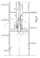
- Figure 2 is an enlarged partial sectional view of the screw area in the area of the inlet space according to another embodiment;
- FIG. 3 shows a section of a third exemplary embodiment comparable to the illustration in FIG. 2;
- FIG. 4 shows a section of a fourth exemplary embodiment which is comparable to the representation according to FIG. 2;
- FIG. 5 shows a section of a last exemplary embodiment, comparable to the representation according to FIG. 2.
Die mit einem Mantel 1 und einer Schnecke 2 ausgerüstete Vollmantel-Schneckenzentrifuge gemäß Ausführungsbeispiel ist lediglich hinsichtlich der an der Zuführseite der Suspension befindlichen Stirnseite bzw. Lagerung und in dem Einlaufbereich in den zwischen dem Mantel 1 und der Schnecke 2 gebildeten Trennraum 3 wiedergegeben. Die Schnecke 2 ist bei 4 an dem Mantel gelagert, dieser wiederum bei 5 an einem ortsfesten Bauteil 6, das hier als Lagerbock angesehen wird. Diese in Figur 1 wiedergegebene Ausführung ist in den übrigen Figuren lediglich hinsichtlich des Einlaufraumbereiches innerhalb der Zentrifuge vergrößert wiedergegeben.The solid-bowl screw centrifuge equipped with a jacket 1 and a
Das Einlaufrohr 31 für die Zuführung der Suspension ist von der nicht dargestellten ortsfesten Eingabestelle der Suspension im rechten Anschlußbereich der Figur 1 als ortsfest stehendes Rohr bis in den Einlaufraum 32 der Schnecke 2 hineingeführt und mit seinem dortigen Endbereich 34 an einem Bolzen 35 abgestützt, der seinerseits in eine in der der Einlaufseite abgewandten Stirnbegrenzungswandung 36 des Einlaufraumes 32 vorgesehene Bohrung 37 eingreift. Radial zwischen dem Bolzen 35 und der inneren Endwandung des Endbereiches 34 des lang ausgebildeten ortsfesten Einlaufrohres 31 ist ein Gleitlager 12 mit den beiden Lagerschalen 14 und 15 angeordnet, so daß eine Abstützung zwischen dem Bolzen 35 und dem Endbereich 34 des Einlaufrohres 31 gegen radiale Schwingungsbewegungen gegeben ist. Die Suspension tritt in Richtung des Pfeiles rechts in das lang ausgebildete Einlaufrohr 31 ein und verläßt dieses durch die Austrittsöffnung 33, die in den Einlaufraum 32 der Schnecke 2 führt, von wo aus die Suspension in üblicher Weise durch Öffnungen in der Schneckennabe in den Trennraum 3 gelangt. Aufgrund der durch das Einlaufrohr 31 aufgegebenen Suspension und deren Aufenthalt in dem Einlaufraum 32 der Schnecke 2 ist das Gleitlager 12 von beiden Stirnseiten her der Suspension ausgesetzt. Die Suspension dient der Bildung eines hydrodynamischen Schmierfilmes für das Gleitlager 12, andererseits sind dessen Laufflächen der von der Suspension ausgehenden Beanspruchung ausgesetzt. Die beiden aneinander gleitend angreifenden Lagerschalen 14 und 15 des Gleitlagers 12 sind aus einem keramischen Werkstoff, hier insbesondere Siliziumkarbit, hergestellt, so daß Abrasions- und Korrisionserscheinungen durch die schmiergelnde Wirkung der Suspensionsfeststoffe an den Gleitflächen nicht oder nur entsprechend geringfügig auftritt.The
Bei dem Ausführungsbeispiel gemäß Figur 1 kann man davon ausgehen, daß das mit dem Gleitlager 12 und dem Bolzen 35 vormontierte Einlaufrohr 31 in die gezeigte Lage von außerhalb der insoweit vormontierten Maschine in Längsrichtung des Einlaufrohres 31 eingeführt wird, wobei der Bolzen 35 über eine beliebige Ausbildung verdrehfest in die Bohrung 37 eingreift. Durch den umgekehrten Montagevorgang läßt sich das Lager leicht inspizieren bzw. auswechseln, ohne daß die Zentrifuge als solche demontiert werden muß.In the embodiment according to FIG. 1, it can be assumed that the
Bei dem Ausführungsbeispiel gemäß Figur 2 ist die Halterung des Endbereiches 34 des Einlaufrohres 31 an einem Bolzen 35 in ähnlicher Weise getroffen wie bei dem Ausführungsbeispiel gemäß Figur 1. Hier ist allerdings ein Sechskant vorgesehen, der es erlaubt, die Lagerschale 14 von dem Bolzen abzuziehen.In the exemplary embodiment according to FIG. 2, the
Beim Ausführungsbeispiel gemäß Figur 2 ist nämlich eine besondere Schmiermittelzufuhr über eine Leitung 39 für den Fall vorgesehen, daß die Suspensionszufuhr unterbrochen wird. Während also die durch die Austrittsöffnung 33 in den Einlaufraum 32 eintretende Suspension die Bildung des hydrodynamischen Schmierfilmes zwischen den Lagerschalen 14 und 15 spätestens von der dem Einlauf abgewandten Stirnseite sicherstellt, wird bei Unterbrechung der Suspensionszufuhr durch die Leitung 39 ein wie auch immer geartetes Schmiermittel zugeführt, das den hydrodynamischen Schmierfilm zwischen den Lagerschalen 14 und 15 aufrechterhält.In the exemplary embodiment according to FIG. 2, a special lubricant supply is provided via a
Im Bereich des Gleitlagers können dabei ein oder mehrere Temperaturfühler vorgesehen sein, durch welche bei Anstieg der Temperatur des Gleitlagers die besondere Schmiermittelzufuhr zu dem Gleitlager selbsttätig eingeschaltet wird. Natürlich kann man hier auch eine Notabschaltung der Zentrifuge vorsehen.In the area of the plain bearing, one or more temperature sensors can be provided, by means of which the special supply of lubricant to the plain bearing is automatically switched on when the temperature of the plain bearing rises. Of course, an emergency shutdown of the centrifuge can also be provided here.
Bei dem Ausführungsbeispiel gemäß Figur 3 ist die Abstützung des Endbereiches 34 des Einlaufrohres 31 über das Gleitlager 12 bzw. dessen Lagerschalen 14 und 15 in ähnlicher Weise wie bei dem Ausführungsbeispiel in Figur 2 getroffen, jedoch ist der Bolzen, an dem die innere Lagerschale 14 beispielsweise über einen Ausgleichskörper 16 gehalten ist, als Hohlbolzen 38 ausgebildet, der eine axial durchgehende Bohrung aufweist. Die der Einlaufseite zugewandte Öffnung dieser durchgehenden Bohrung ist auf einen Einlauf zu gerichtet, der ähnlich demjenigen der Notlaufschmierflüssigkeit gemäß Figur 2 ausgebildet ist, im vorliegenden Ausführungsbeispiel gemäß Figur 3 jedoch der Zuführung einer Waschflüssigkeit dient, die somit die Schmierung des Lagers 12 sicherstellt und gleichzeitig eine Waschflüssigkeit in den Innenraum der Schnecke zuführt, der sich an die dem Suspensionseinlauf abgewandte Wandung 36 des Einlaufraumes 32 anschließt. Dieser Raum weist in der Schneckennabe kleine Durchtrittsbohrungen auf, durch welche die Waschflüssigkeit in den Trennraum der Zentrifuge gelangt, und zwar in dessen konischen Mantelbereich, um Feststoffe abzuspülen.In the exemplary embodiment according to FIG. 3, the
Der Ausgleichskörper 16 dient der Kompensation von temperaturbedingten Maßänderungen, er ist in radialer Richtung elastisch nachgiebig ausgebildet. Damit wird erreicht, daß bei Temperaturerhöhung der sich stärker dehnende Mantel des Endbereiches 34 des Einlaufrohres 31 bzw. - im Hinblick auf Figur 1 - die Durchmessererhöhung des Bolzens 35 die sich bei dieser Temperatur weit weniger ausdehnende keramische Lagerschale auf Zug belastet, wogegen der keramische Werkstoff empfindlich ist. Der rohrförmige Ausgleichskörper weist eine in sich wellige Mantelwandung auf, und zwar mit dem Wellenverlauf in Umfangsrichtung gesehen, oder auch mit dem Wellenverlauf in Achsrichtung gesehen, wie dies in der Zeichnung angedeutet ist. Die radial äußere Lagerschale ist - je nach Ausführungsbeispiel an der Innenmantelwandung des Endbereiches 34 des Einlaufrohres 31 oder der Wandung 36 bzw. 43 (Figur 5) des Schneckenkörpers - dadurch befestigt, daß dieser vor Einsetzen der Lagerschale 15 aufgeheizt wird. Bei Abkühlung führen die unterschiedlichen Wärmeausdehnungskoeffizienten des Einlaufrohres bzw. der Schneckenkörperwandung - beispielsweise Stahl - einerseits und des Keramikörpers andererseits dazu, daß die Lagerschale durch Schrumpfen in ihrer Position festgelegt und somit zusammengedrückt wird, wogegen der Keramikwerkstoff unempfindlich ist.The compensating
Bei dem Ausführungsbeispiel gemäß Figur 4 ist die Zuführung von Waschflüssigkeit mit Hilfe eines Waschflüssigkeitszuführrohres 40 getroffen, das in sich starr ist und als Verbindung zwischen dem Gleitlager 12 und dem Endbereich 34 des Einlaufrohres 31 insoweit dient, als die Innenwandung des Endbereiches 34 des Einlaufrohres 31 über radiale Stege 42 an der Außenmantelwandung des Waschflüssigkeitszuführrohres 40 abgestützt ist. Diese Abstützung erfolgt im Nahbereich des Gleitlagers 12, welches im Durchtrittsbereich des Waschflüssigkeitszuführrohres 40 durch die der Einlaufseite abgewandte stirnseitige Wandung 36 des Einlaufraumes 32 angeordnet ist. Dabei ist die äußere Lagerschale 15 an der Innenwandung einer entsprechenden Bohrung in der Trennwand abgestützt, während die innere Lagerschale 14 an der Außenmantelwandung des Waschflüssigkeitszuführrohres 40 abgestützt ist. Hier bildet demnach das Gleitlager 12 eine Dichtung zwischen dem Raum, in den die Waschflüssigkeit eingeleitet wird, und dem Einlaufraum 32, in den das Einlaufrohr 31 stirnseitig mündet.In the exemplary embodiment according to FIG. 4, the supply of washing liquid is made with the aid of a washing
Bei dem Ausführungsbeispiel gemäß Figur 5 dagegen ist wieder ein sehr einfacher Fall der Suspensionszuführung gezeigt, bei welchem Notlaufschmierung und Waschflüssigkeitszufuhr nicht vorgesehen sind. In diesem Falle ist das Gleitlager 12 im Durchtrittsbereich des Einlaufrohres 31 durch diejenige stirnseitige Trennwandung 43 des Einlaufraumes 32 der Schnecke 2 angeordnet, die dem Suspensionseinlauf zugewandt liegt. Die Außenschale des Gleitlagers 12 ist an der Innenwand einer entsprechenden Bohrung in der Stirntrennwandung 43 abgestützt, während die innere Lagerschale 14 an der äußeren Mantelfläche des Einlaufrohres 31 angreift.In the exemplary embodiment according to FIG. 5, on the other hand, a very simple case of the suspension supply is again shown, in which emergency lubrication and washing liquid supply are not provided. In this case, the
Claims (13)
dadurch gekennzeichnet,
daß das sich bis in einen Einlaufraum (32) der Schnecke (2) erstreckende Einlaufrohr (31) in seinem dortigen Endbereich (34) an einem schneckenfesten Teil (36, 35; 36, 38; 36; 43) über ein Gleitlager (12) abgestützt ist, dessen beide Lagerschalen (14, 15) im Gleitangriffsbereich aus einem keramischen Werkstoff bestehen.1. Solid bowl screw centrifuge, in particular countercurrent centrifuge, for the separation of a suspension, for its supply from a fixed input point outside the centrifuge in the separation space (3) of the centrifuge formed between the screw (2) and the shell (1) stationary inlet pipe (31) is provided,
characterized by
that the inlet pipe (31) extending into an inlet space (32) of the screw (2) in its end region (34) there on a screw-fixed part (36, 35; 36, 38; 36; 43) via a slide bearing (12) is supported, the two bearing shells (14, 15) in the sliding engagement area made of a ceramic material.
dadurch gekennzeichnet,
daß der keramische Werkstoff des Gleitlagers (12) eine oxidfreie Keramik ist, insbesondere aus oder auf der Basis von reinem Siliziumkarbit gebildet ist.2. centrifuge according to claim 1,
characterized by
that the ceramic material of the slide bearing (12) is an oxide-free ceramic, in particular formed from or on the basis of pure silicon carbide.
dadurch gekennzeichnet,
daß die radial außen angeordnete Lagerschale (15) an ihrer Außenseite schrumpfdruckbelastet festgelegt ist.3. centrifuge according to claim 1 or 2,
characterized by
that the radially outer bearing shell (15) is fixed on its outside with shrinkage pressure.
dadurch gekennzeichnet,
daß die radial innen angeordnete Lagerschale (14) mit ihrer Innenmantelfläche über einen zwischengeschalteten Temperaturspannungs-Ausgleichskörper (16) an einem Abschnitt der Außenwandung des die Lagerschale (15) haltenden Bauelementes festgelegt ist.4. Centrifuge according to one of claims 1 to 3,
characterized by
that the radially inner bearing shell (14) is fixed with its inner lateral surface via an interposed temperature-voltage compensation body (16) to a section of the outer wall of the component holding the bearing shell (15).
dadurch gekennzeichnet,
daß der Temperatur-Ausgleichskörper (16) als radial nachgiebiger Ring oder Rohrabschnitt ausgebildet ist, insbesondere mit einer in sich gewellten Mantelwandung.5. centrifuge according to claim 4,
characterized by
that the temperature compensation body (16) is designed as a radially flexible ring or tube section, in particular with a corrugated jacket wall.
daß sich zwischen den aneinander gleitenden Lagerschalenflächen des Gleitlagers (12) bei Anwesenheit eines flüssigen Mediums ein hydrodynamischer Schmierfilm aufbaut.6. Centrifuge according to one of claims 1 to 5, characterized in
that a hydrodynamic lubricating film builds up between the sliding bearing shell surfaces of the slide bearing (12) in the presence of a liquid medium.
dadurch gekennzeichnet,
daß das Gleitlager (12) mit dem Innenraum des Einlaufrohres (31) in Verbindung steht und durch die über das Einlaufrohr (31) in den Trennraum (3) der Zentrifuge eingeleitete Suspension geschmiert wird.7. centrifuge according to claim 6,
characterized by
that the slide bearing (12) communicates with the interior of the inlet pipe (31) and is lubricated by the suspension introduced via the inlet pipe (31) into the separation chamber (3) of the centrifuge.
dadurch gekennzeichnet,
daß eine Ersatzflüssigkeit zur Schmierung des Gleitlagers (12) vorgesehen ist, die bei Unterbrechung der Zugabe der Suspension selbsttätig zugeführt wird.8. centrifuge according to claim 6 or 7,
characterized by
that a replacement liquid for lubricating the slide bearing (12) is provided, which is interrupted when the addition the suspension is fed automatically.
daß für die Schmierflüssigkeit zur Versorgung des Gleitlagers (12) eine separate Leitung (39; 40) vorgesehen ist.9. Centrifuge according to one of claims 6 to 8, characterized in
that a separate line (39; 40) is provided for the lubricating fluid for supplying the slide bearing (12).
daß im Bereich des Gleitlagers (12) ein oder mehrere Temperaturfühler vorgesehen sind, die bei Anstieg der Temperatur des Gleitlagers über einen bestimmten Wert der Schmiermittelversorgung des Gleitlagers selbsttätig einschalten oder die Zentrifuge abschalten.10. Centrifuge according to one of claims 6 to 9, characterized in
that one or more temperature sensors are provided in the area of the slide bearing (12), which switch on automatically when the temperature of the slide bearing rises above a certain value for the lubricant supply to the slide bearing or switch off the centrifuge.
daß der Schneckenkörper im konischen Bereich der Zentrifuge mit einem Hohlraum zur Einleitung von Waschflüssigkeit versehen ist und daß im Übertrittsbereich der stationären Zuleitung für die Waschflüssigkeit auf den umlaufenden Schneckenkörper das Gleitlager (12) als Dichtung angeordnet ist.11. Centrifuge according to one of claims 1 to 10, characterized in
that the screw body in the conical area of the centrifuge is provided with a cavity for the introduction of washing liquid and that the slide bearing (12) is arranged as a seal in the transition area of the stationary feed line for the washing liquid to the rotating screw body.
daß das Waschflüssigkeitszuführrohr (40) als stationäres Rohr über das Gleitlager (12) mit den keramischen Lagerschalen (14, 15) in der Schnecke gelagert ist und daß das für die Einleitung der Suspension dienende Einlaufrohr (31) sich auf dem Waschflüssigkeitszuführrohr (40) abstützt (42).12. Centrifuge according to one of claims 1 to 11, characterized in
that the washing liquid supply pipe (40) is mounted as a stationary pipe via the slide bearing (12) with the ceramic bearing shells (14, 15) in the screw and that the inlet pipe (31) serving to introduce the suspension is supported on the washing liquid supply pipe (40) (42).
daß das Einlaufrohr (31) in der dem Suspensionseinlauf zugewandten Stirntrennwandung (43) des Einlaufraumes (32) der Zentrifuge über das Gleitlager (12) abgestützt ist.13. Centrifuge according to one of claims 1 to 7, characterized in
that the inlet pipe (31) in the suspension inlet facing end partition (43) of the inlet space (32) of the centrifuge is supported by the slide bearing (12).
Applications Claiming Priority (2)
| Application Number | Priority Date | Filing Date | Title |
|---|---|---|---|
| DE3816210 | 1988-05-11 | ||
| DE19883816210 DE3816210A1 (en) | 1986-11-12 | 1988-05-11 | FULL-COVERED SNAIL CENTRIFUGE |
Publications (3)
| Publication Number | Publication Date |
|---|---|
| EP0341433A2 true EP0341433A2 (en) | 1989-11-15 |
| EP0341433A3 EP0341433A3 (en) | 1990-04-25 |
| EP0341433B1 EP0341433B1 (en) | 1993-08-04 |
Family
ID=6354231
Family Applications (1)
| Application Number | Title | Priority Date | Filing Date |
|---|---|---|---|
| EP89106271A Expired - Lifetime EP0341433B1 (en) | 1988-05-11 | 1989-04-10 | Solid bowl screw conveyor centrifuge |
Country Status (4)
| Country | Link |
|---|---|
| US (1) | US4957475A (en) |
| EP (1) | EP0341433B1 (en) |
| JP (1) | JPH01317560A (en) |
| DK (1) | DK228589A (en) |
Cited By (4)
| Publication number | Priority date | Publication date | Assignee | Title |
|---|---|---|---|---|
| EP0438767A3 (en) * | 1990-01-25 | 1991-12-04 | Basf Aktiengesellschaft | Process for the separation of riboflavin from a fermentation suspension |
| US20150238977A1 (en) * | 2014-02-26 | 2015-08-27 | Ferrum Ag | Centrifuge and method of loading a centrifuge |
| WO2019007886A1 (en) * | 2017-07-06 | 2019-01-10 | Gea Mechanical Equipment Gmbh | FULL COAT SCREW CENTRIFUGE |
| EP4295957A1 (en) * | 2022-06-24 | 2023-12-27 | Hermeler, Jürgen | Decanter centrifuge |
Families Citing this family (10)
| Publication number | Priority date | Publication date | Assignee | Title |
|---|---|---|---|---|
| US5156751A (en) * | 1991-03-29 | 1992-10-20 | Miller Neal J | Three stage centrifuge and method for separating water and solids from petroleum products |
| US5403486A (en) * | 1991-12-31 | 1995-04-04 | Baker Hughes Incorporated | Accelerator system in a centrifuge |
| US5364335A (en) * | 1993-12-07 | 1994-11-15 | Dorr-Oliver Incorporated | Disc-decanter centrifuge |
| DK0868215T3 (en) * | 1995-12-01 | 2002-05-06 | Baker Hughes Inc | Method and apparatus for controlling and monitoring a continuous supply centrifuge |
| US8328877B2 (en) | 2002-03-19 | 2012-12-11 | Boston Scientific Scimed, Inc. | Stent retention element and related methods |
| DK200970026A (en) * | 2009-06-12 | 2010-12-13 | Alfa Laval Corp Ab | A centrifugal separator |
| US8651240B1 (en) | 2012-12-24 | 2014-02-18 | United Technologies Corporation | Pressurized reserve lubrication system for a gas turbine engine |
| DE102012018241B4 (en) * | 2012-09-17 | 2014-12-18 | Gea Mechanical Equipment Gmbh | separator |
| JP2017189752A (en) * | 2016-04-15 | 2017-10-19 | 日本フローサーブ株式会社 | Vertical type solid-liquid separation equipment |
| DE102018119279A1 (en) * | 2018-08-08 | 2020-02-13 | Gea Mechanical Equipment Gmbh | Solid bowl centrifuge |
Family Cites Families (14)
| Publication number | Priority date | Publication date | Assignee | Title |
|---|---|---|---|---|
| FR1251684A (en) * | 1960-03-18 | 1961-01-20 | Krupp Dolberg Gmbh | Centrifugal worm machine |
| US3172851A (en) * | 1962-08-31 | 1965-03-09 | Centrifuging liquid-solids mixtures | |
| US3326457A (en) * | 1964-02-14 | 1967-06-20 | United States Steel Corp | Method and apparatus for steamassisted centrifugal dewatering |
| US3379368A (en) * | 1965-12-06 | 1968-04-23 | Gilreath Hydraulies Inc | Centrifugal separator |
| US3568919A (en) * | 1968-01-10 | 1971-03-09 | Titan Separator As | Screw centrifuge |
| US3575709A (en) * | 1968-08-20 | 1971-04-20 | Bird Machine Co | Method of cleaning sugar crystals |
| DE2160493A1 (en) * | 1971-12-07 | 1973-06-14 | Erich Rosenthal | DISTRIBUTION RING FOR PNEUMATIC MEDIA FOR LUBRICATING AND COOLING ROTATING FRICTION SURFACES |
| US3854658A (en) * | 1973-05-07 | 1974-12-17 | Dorr Oliver Inc | Solid bowl conveyer type centrifuge |
| US4334647A (en) * | 1980-12-03 | 1982-06-15 | Bird Machine Company, Inc. | Centrifuges |
| DE3326310C2 (en) * | 1983-07-21 | 1986-02-20 | Westfalia Separator Ag, 4740 Oelde | Solid bowl centrifuge with a screw conveyor |
| AU579834B2 (en) * | 1983-09-30 | 1988-12-15 | Ebara Corporation | Combination of slide members |
| DE3509572C1 (en) * | 1985-03-16 | 1986-07-10 | Feldmühle AG, 4000 Düsseldorf | Sliding element coated with ceramic material components and its use |
| DE3638652A1 (en) * | 1986-11-12 | 1988-06-01 | Flottweg Bird Mach Gmbh | Solid-bowl worm centrifuge |
| DE8706954U1 (en) * | 1987-05-14 | 1987-07-02 | Hermetic-Pumpen Gmbh, 7803 Gundelfingen | Plain bearings for pumps |
-
1989
- 1989-04-10 EP EP89106271A patent/EP0341433B1/en not_active Expired - Lifetime
- 1989-05-04 US US07/347,758 patent/US4957475A/en not_active Expired - Fee Related
- 1989-05-10 JP JP1118486A patent/JPH01317560A/en active Pending
- 1989-05-10 DK DK228589A patent/DK228589A/en not_active Application Discontinuation
Cited By (8)
| Publication number | Priority date | Publication date | Assignee | Title |
|---|---|---|---|---|
| EP0438767A3 (en) * | 1990-01-25 | 1991-12-04 | Basf Aktiengesellschaft | Process for the separation of riboflavin from a fermentation suspension |
| US5169759A (en) * | 1990-01-25 | 1992-12-08 | Basf Aktiengesellschaft | Removal of riboflavin from fermentation suspensions |
| US20150238977A1 (en) * | 2014-02-26 | 2015-08-27 | Ferrum Ag | Centrifuge and method of loading a centrifuge |
| EP2913112A1 (en) * | 2014-02-26 | 2015-09-02 | Ferrum AG | Centrifuge, and method for loading a centrifuge |
| US10639647B2 (en) * | 2014-02-26 | 2020-05-05 | Ferrum Ag | Centrifuge with a feed device comprising a feed direction control and method of loading a centrifuge with a feed device comprising a feed direction control |
| WO2019007886A1 (en) * | 2017-07-06 | 2019-01-10 | Gea Mechanical Equipment Gmbh | FULL COAT SCREW CENTRIFUGE |
| EP4295957A1 (en) * | 2022-06-24 | 2023-12-27 | Hermeler, Jürgen | Decanter centrifuge |
| WO2023247183A1 (en) * | 2022-06-24 | 2023-12-28 | Hermeler Prof Dr Juergen | Decanter centrifuge |
Also Published As
| Publication number | Publication date |
|---|---|
| JPH01317560A (en) | 1989-12-22 |
| EP0341433B1 (en) | 1993-08-04 |
| US4957475A (en) | 1990-09-18 |
| DK228589A (en) | 1989-11-12 |
| EP0341433A3 (en) | 1990-04-25 |
| DK228589D0 (en) | 1989-05-10 |
Similar Documents
| Publication | Publication Date | Title |
|---|---|---|
| EP0341433B1 (en) | Solid bowl screw conveyor centrifuge | |
| DE3619489C2 (en) | ||
| DE3106318C1 (en) | Sealing arrangement with cooling device | |
| DE60212451T2 (en) | OUTSIDE FIXED SPIRAL ADAPTER | |
| DE10229406A1 (en) | Device for the continuous filtering of material mixtures | |
| AT523264B1 (en) | Process for the production of a sieve body and sieve | |
| DE8816668U1 (en) | Power operated chuck | |
| EA036223B1 (en) | DEVICE FOR FLUID OR BULK RAW MATERIAL DEHYDRATION | |
| US3980013A (en) | Split worm for screw press | |
| DE1782548B2 (en) | Solid bowl screw centrifuge | |
| DE202021106173U1 (en) | Mechanical sealing device for sealing liquids | |
| DE1817573A1 (en) | Screw centrifuge | |
| DE19847103C1 (en) | Continuously working fluid material processing machine | |
| DE1425968A1 (en) | Fluid bearings | |
| EP0857258B1 (en) | Device for coupling coolant duct of a rotating part | |
| DE3129403C2 (en) | Device for supplying coolant to rotating cutting tools provided with coolant channels for metal cutting, in particular drilling tools. | |
| DE10132688A1 (en) | Bottom bracket for screw machines | |
| EP0731284B1 (en) | Clamp for cylindric elements | |
| DE4326150C2 (en) | Device for the axial fixing of components | |
| DE3638652C2 (en) | ||
| DE2520667C2 (en) | Screw pump | |
| DE102016115039A1 (en) | tool holder | |
| DE19621773A1 (en) | External compressed air bearing spindle | |
| DE3816210A1 (en) | FULL-COVERED SNAIL CENTRIFUGE | |
| DE10217181B4 (en) | Device for limiting leakage currents on shaft bushings |
Legal Events
| Date | Code | Title | Description |
|---|---|---|---|
| PUAI | Public reference made under article 153(3) epc to a published international application that has entered the european phase |
Free format text: ORIGINAL CODE: 0009012 |
|
| AK | Designated contracting states |
Kind code of ref document: A2 Designated state(s): FR GB IT |
|
| PUAL | Search report despatched |
Free format text: ORIGINAL CODE: 0009013 |
|
| AK | Designated contracting states |
Kind code of ref document: A3 Designated state(s): FR GB IT |
|
| 17P | Request for examination filed |
Effective date: 19900530 |
|
| 17Q | First examination report despatched |
Effective date: 19910722 |
|
| ITF | It: translation for a ep patent filed | ||
| GRAA | (expected) grant |
Free format text: ORIGINAL CODE: 0009210 |
|
| AK | Designated contracting states |
Kind code of ref document: B1 Designated state(s): FR GB IT |
|
| ET | Fr: translation filed | ||
| GBT | Gb: translation of ep patent filed (gb section 77(6)(a)/1977) |
Effective date: 19931011 |
|
| ITTA | It: last paid annual fee | ||
| PLBE | No opposition filed within time limit |
Free format text: ORIGINAL CODE: 0009261 |
|
| STAA | Information on the status of an ep patent application or granted ep patent |
Free format text: STATUS: NO OPPOSITION FILED WITHIN TIME LIMIT |
|
| 26N | No opposition filed | ||
| PGFP | Annual fee paid to national office [announced via postgrant information from national office to epo] |
Ref country code: GB Payment date: 19980402 Year of fee payment: 10 |
|
| PG25 | Lapsed in a contracting state [announced via postgrant information from national office to epo] |
Ref country code: GB Free format text: LAPSE BECAUSE OF NON-PAYMENT OF DUE FEES Effective date: 19990410 |
|
| GBPC | Gb: european patent ceased through non-payment of renewal fee |
Effective date: 19990410 |
|
| PGFP | Annual fee paid to national office [announced via postgrant information from national office to epo] |
Ref country code: FR Payment date: 20000428 Year of fee payment: 12 |
|
| PG25 | Lapsed in a contracting state [announced via postgrant information from national office to epo] |
Ref country code: FR Free format text: THE PATENT HAS BEEN ANNULLED BY A DECISION OF A NATIONAL AUTHORITY Effective date: 20010430 |
|
| REG | Reference to a national code |
Ref country code: FR Ref legal event code: ST |
|
| PG25 | Lapsed in a contracting state [announced via postgrant information from national office to epo] |
Ref country code: IT Free format text: LAPSE BECAUSE OF NON-PAYMENT OF DUE FEES;WARNING: LAPSES OF ITALIAN PATENTS WITH EFFECTIVE DATE BEFORE 2007 MAY HAVE OCCURRED AT ANY TIME BEFORE 2007. THE CORRECT EFFECTIVE DATE MAY BE DIFFERENT FROM THE ONE RECORDED. Effective date: 20050410 |