EP0341427A2 - Monomode-Lichtleitfaser und Verfahren zu deren Herstellung - Google Patents
Monomode-Lichtleitfaser und Verfahren zu deren Herstellung Download PDFInfo
- Publication number
- EP0341427A2 EP0341427A2 EP89106144A EP89106144A EP0341427A2 EP 0341427 A2 EP0341427 A2 EP 0341427A2 EP 89106144 A EP89106144 A EP 89106144A EP 89106144 A EP89106144 A EP 89106144A EP 0341427 A2 EP0341427 A2 EP 0341427A2
- Authority
- EP
- European Patent Office
- Prior art keywords
- refractive index
- optical fiber
- mode optical
- fiber according
- maximum
- Prior art date
- Legal status (The legal status is an assumption and is not a legal conclusion. Google has not performed a legal analysis and makes no representation as to the accuracy of the status listed.)
- Withdrawn
Links
Images


Classifications
-
- G—PHYSICS
- G02—OPTICS
- G02B—OPTICAL ELEMENTS, SYSTEMS OR APPARATUS
- G02B6/00—Light guides; Structural details of arrangements comprising light guides and other optical elements, e.g. couplings
- G02B6/02—Optical fibres with cladding with or without a coating
- G02B6/02004—Optical fibres with cladding with or without a coating characterised by the core effective area or mode field radius
- G02B6/02009—Large effective area or mode field radius, e.g. to reduce nonlinear effects in single mode fibres
-
- G—PHYSICS
- G02—OPTICS
- G02B—OPTICAL ELEMENTS, SYSTEMS OR APPARATUS
- G02B6/00—Light guides; Structural details of arrangements comprising light guides and other optical elements, e.g. couplings
- G02B6/02—Optical fibres with cladding with or without a coating
- G02B6/02214—Optical fibres with cladding with or without a coating tailored to obtain the desired dispersion, e.g. dispersion shifted, dispersion flattened
- G02B6/02219—Characterised by the wavelength dispersion properties in the silica low loss window around 1550 nm, i.e. S, C, L and U bands from 1460-1675 nm
- G02B6/02228—Dispersion flattened fibres, i.e. having a low dispersion variation over an extended wavelength range
- G02B6/02233—Dispersion flattened fibres, i.e. having a low dispersion variation over an extended wavelength range having at least two dispersion zero wavelengths
-
- G—PHYSICS
- G02—OPTICS
- G02B—OPTICAL ELEMENTS, SYSTEMS OR APPARATUS
- G02B6/00—Light guides; Structural details of arrangements comprising light guides and other optical elements, e.g. couplings
- G02B6/02—Optical fibres with cladding with or without a coating
- G02B6/036—Optical fibres with cladding with or without a coating core or cladding comprising multiple layers
- G02B6/03605—Highest refractive index not on central axis
- G02B6/03611—Highest index adjacent to central axis region, e.g. annular core, coaxial ring, centreline depression affecting waveguiding
-
- G—PHYSICS
- G02—OPTICS
- G02B—OPTICAL ELEMENTS, SYSTEMS OR APPARATUS
- G02B6/00—Light guides; Structural details of arrangements comprising light guides and other optical elements, e.g. couplings
- G02B6/02—Optical fibres with cladding with or without a coating
- G02B6/036—Optical fibres with cladding with or without a coating core or cladding comprising multiple layers
- G02B6/03616—Optical fibres characterised both by the number of different refractive index layers around the central core segment, i.e. around the innermost high index core layer, and their relative refractive index difference
- G02B6/03638—Optical fibres characterised both by the number of different refractive index layers around the central core segment, i.e. around the innermost high index core layer, and their relative refractive index difference having 3 layers only
- G02B6/03644—Optical fibres characterised both by the number of different refractive index layers around the central core segment, i.e. around the innermost high index core layer, and their relative refractive index difference having 3 layers only arranged - + -
-
- G—PHYSICS
- G02—OPTICS
- G02B—OPTICAL ELEMENTS, SYSTEMS OR APPARATUS
- G02B6/00—Light guides; Structural details of arrangements comprising light guides and other optical elements, e.g. couplings
- G02B6/02—Optical fibres with cladding with or without a coating
- G02B6/036—Optical fibres with cladding with or without a coating core or cladding comprising multiple layers
- G02B6/03616—Optical fibres characterised both by the number of different refractive index layers around the central core segment, i.e. around the innermost high index core layer, and their relative refractive index difference
- G02B6/03661—Optical fibres characterised both by the number of different refractive index layers around the central core segment, i.e. around the innermost high index core layer, and their relative refractive index difference having 4 layers only
- G02B6/03672—Optical fibres characterised both by the number of different refractive index layers around the central core segment, i.e. around the innermost high index core layer, and their relative refractive index difference having 4 layers only arranged - - + -
-
- G—PHYSICS
- G02—OPTICS
- G02B—OPTICAL ELEMENTS, SYSTEMS OR APPARATUS
- G02B6/00—Light guides; Structural details of arrangements comprising light guides and other optical elements, e.g. couplings
- G02B6/02—Optical fibres with cladding with or without a coating
- G02B6/036—Optical fibres with cladding with or without a coating core or cladding comprising multiple layers
- G02B6/03616—Optical fibres characterised both by the number of different refractive index layers around the central core segment, i.e. around the innermost high index core layer, and their relative refractive index difference
- G02B6/03688—Optical fibres characterised both by the number of different refractive index layers around the central core segment, i.e. around the innermost high index core layer, and their relative refractive index difference having 5 or more layers
Definitions
- the invention relates to a single-mode optical fiber with a refractive index profile n (r), where n is the refractive index of the fiber material at a distance r from the axis of the fiber, the refractive index profile by doping a matrix material, of which the fiber consists predominantly, with at least one doping material is set to form a number of layers with different refractive index.
- n is the refractive index of the fiber material at a distance r from the axis of the fiber
- the refractive index profile by doping a matrix material, of which the fiber consists predominantly, with at least one doping material is set to form a number of layers with different refractive index.
- the invention also relates to a method for its production.
- a monomode fiber with a refractive index profile is known, which is designed such that the fiber particularly fulfills three conditions with regard to chromatic dispersion: these are zeros at two preselected wavelengths and a predetermined maximum value.
- the refractive index profile is made up of three layers and shows a W-shaped course. It is not optimized with regard to the amount of doping material.
- the object of the invention is to provide a single-mode optical fiber which manages with as little doping material as possible for given properties.
- the object of the invention is also to provide a method for producing such an optical fiber.
- the fulfillment of the condition according to the invention means a minimization of the amount of the doping material and thus a corresponding reduction in the manufacturing outlay, since with the usual concentrations of doping material the resulting difference in refractive index from the undoped material is essentially proportional to the concentration of the doping material. In the case of conventional doping materials, this also applies at least approximately when there are several different doping materials, in particular a doping material which increases the refractive index and lowers the refractive index. Under these circumstances, the fulfillment of the condition according to the invention corresponds particularly well to minimizing the amount of the doping material if the effects of the refractive index changing effects of the two doping materials are essentially the same.
- the fiber is built up by changing the refractive index layer by layer.
- the requirements according to the invention can also be met with a larger number of desired properties without unnecessarily large jumps in refractive index and without an excessive deviation from the refractive index of the matrix material in that the number of layers is large compared to the number of desired properties.
- This is possible, for example, in the known plasma production processes, in which the number of possible layers and thus the number of degrees of freedom available for the design of the fiber according to the invention is approximately 1,000 (PCVD process) or even 1,000,000 (PICVD- Procedure) has risen.
- PCVD process PCVD process
- PICVD- Procedure 1,000,000
- the number of layers included in the calculation will not be too large. In general, it is sufficient if more than 100 layers are selected during the production, preferably about 300 to 500 layers.
- the fiber according to the invention is a multilayer fiber that has a characteristic sequence of almost triangular increases and decreases in the refractive index level with flat zones in between along the radius, whereby known coarse structures, namely a first, strongly pronounced minimum refractive index following a core with a relatively high refractive index, follow one another Find the following pronounced first maximum refractive index, a weak second minimum and a run-out area (EP-OS 0 224 282).
- there is a second maximum at the outer edge of the core which makes it possible to increase the chromatic dispersion at approximately 1,300 nm, which has an undesirably high negative value in known fibers, preferably to zero.
- there are several turning points between the first maximum and the second minimum This allows the refractive index to drop economically from the first maximum to the second minimum. This applies in particular if there is a step at the level of undoped matrix material, preferably SiO z , between the first maximum and the second minimum.
- a third maximum is provided in the run-out area, in which the refractive index is preferably at the level of undoped matrix material. This leads to an increase in the tunneling probability for the LP 11 photons from the core into the material located further out and thus to a favorable influence on the upper mode cutoff, ie an increase in the upper mode damping. This third maximum is so far out that it no longer disturbs the basic mode with regard to damping and dispersion.
- Refractive index profiles for the fibers according to the invention can be determined mathematically with little effort. A particularly simple possibility of such a mathematical determination is to be explained in more detail below.
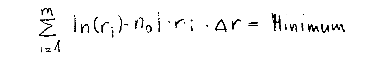
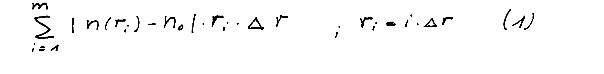
- the condition according to the invention is formulated mathematically: one searches for a minimum of the function where the 1 desired properties define the permissible range in Rm, the space of the refractive indices n (r ; ) - n o , as secondary conditions, ie you can work with a quasi-continuous profile, e.g. a few hundred equidistant layers.
- this sum represents an approximation of the following integral: where R 2 represents the radius of the fiber.
- the associated fiber is calculated with the refractive index profile according to the invention in two steps. First, based on a slightly rounded step index profile, an element of the permissible range is sought using a method of the Newton type, i.e. a refractive index profile that gives the desired properties except for the minimization condition. Then you get to the minimum with the method of the projected gradient.
- the jacket may consist of pure quartz glass (Si0 2 ).
- This refractive index profile is like others by the vector formed from the refractive indices of the individual layers n described.
- the 1 (generally nonlinear) constraints are linearized locally
- a matrix M is also introduced, which contains the gradients of the constraints in its rows, and the requirements for the vector are thus formulated
- the chromatic dispersion is calculated by numerically differentiating the group delay, whereby the mode field and propagation constant are determined numerically, for example according to U. Foringham, D. Krause, R. Kunststoffmann, "Calculations to Determine the Effective Cutoff Wavelength of Single-Mode Fibers ", JOpt.Commun.8, 4, pp.143-147, 1987, and AWSnyder, JdLove," Optical Waveguide Theory ", London. New York: Chapman and Hall, 1983 ".
- n (r) The change in the refractive index profile A n (r) is assumed to be independent of the wavelength, but not the initial refractive index profile, which is recalculated for each wavelength from the concentration profile of the doping materials. This concentration profile is in turn recalculated for each step of the interation. So for the gradient: where n (r k ) has been designated n k .
- the damping of the LP 01 and LP 11 modes is calculated according to the work by Fotheringham et al. There is the loss per length with given here, the ratio of the field amplitude square on the fiber radius R 2 weighted by the radius calculated here using the WKB method (cf., for example, H.-G.Unger, "Optical Communication Technology", Part I, Heidelberg (1984) 92) to that at the effective core radius R 1 from the numerical field calculation. With R o the inner caustic is called.
- k r, inf stands for the radial component of the wave number in the medium surrounding the fiber.
- the damping calculations serve to determine the basic mode damping (see above c)) and to determine the upper mode damping (upper mode cutoff, see above b)).
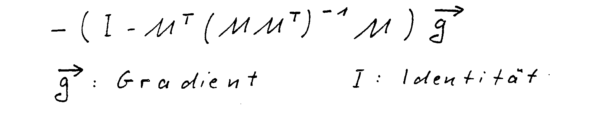
- the process is terminated when the L z norm of the projected gradient has become much smaller than that of the non-projected gradient (ie smaller than a corresponding arbitrary limit, approximately 0.1).
- the curve shown in FIG. 1 relates to the profile from FIG. 5. It should be noted that the refractive indices were varied in 1/10 ⁇ m intervals from zero radius to 35 ⁇ m radius.
- the profile has a characteristic sequence of almost triangular increases and decreases in the refractive index level with flat zones in between, with known coarse structures, namely a Find the core 1 of relatively high refractive index following the first, highly pronounced refractive index minimum 2, a subsequent first pronounced refractive index maximum 4, a weak second minimum 5 and a run-out area 6 (EP-OS 0 224 282).
- the gradual decrease in the refractive index in FIG. 4 from the first refractive index maximum 4 to the second refractive index minimum 5 can be made more economical if it is carried out in a step-wise manner and keeps a step at the level of the matrix material. So there are several turning points, e.g. 8, 9, 10, provided there.
- the first refractive index minimum 2 is relatively low. This can cause technical difficulties. It is therefore usually advisable to introduce a minimum value of the refractive index, which should not be undercut, into the calculation process as the desired property. This can be taken into account in the calculation by introducing lower refractive index barriers according to the type of "penalty" functions in the above-mentioned standard.
- the result of the calculation is then a natural refractive index profile which has a third refractive index maximum 11 in the outlet area 6.
- Such a refractive index profile is shown in FIG. 8.
- the third maximum 11 causes an increase in the tunneling probability for the LP11 photons from the core zone into the material surrounding the fiber and thus a favorable influence on the upper mode cutoff, i.e. an increase in upper mode damping.
- the third maximum 11 is so far out that it no longer disturbs the basic mode (i.e. its damping and dispersion).
- the third maximum had also set in early in the calculation process without establishing a low refractive index value, as can be seen from FIG. 4. But it had disappeared again on the way along the projected gradient.
- the present invention was made as part of a doctoral thesis at the Johannes Gutenberg University Mainz, Department of Physics.
Landscapes
- Physics & Mathematics (AREA)
- General Physics & Mathematics (AREA)
- Optics & Photonics (AREA)
- Chemical & Material Sciences (AREA)
- Dispersion Chemistry (AREA)
- Glass Compositions (AREA)
- Optical Fibers, Optical Fiber Cores, And Optical Fiber Bundles (AREA)
- Lasers (AREA)
- Manufacture, Treatment Of Glass Fibers (AREA)
Abstract
Description
- Die Erfindung betrifft eine Monomode-Lichtleitfaser mit einem Brechzahlprofil n (r), wobei n die Brechzahl des Fasermaterials im Abstand r von der Achse der Faser bedeutet, wobei das Brechzahlprofil durch Dotieren eines Matrixmaterials, aus dem die Faser überwiegend besteht, mit wenigstens einem Dotiermaterial unter Ausbildung einer Anzahl von Schichten mit unterschiedlicher Brechzahl eingestellt ist. Die Erfindung betrifft auch ein Verfahren zu seiner Herstellung.
- Aus der DE-OS 32 32 194 ist eine Monomodefaser mit einem Brechzahlprofil bekannt, das derart ausgelegt ist, daß die Faser hinsichtlich der chromatischen Dispersion insbesondere drei Bedingungen erfüllt: dies sind Nullstellen bei zwei vorgewählten Wellenlängen und ein vorgegebener Maximalwert. Das Brechzahlprofil ist aus drei Schichten aufgebaut und zeigt einen W-förmigen Verlauf. Es ist bezüglich der Dotiermaterialmenge nicht optimiert.
- Aufgabe der Erfindung ist es, eine Monomode-Lichtleitfaser zu schaffen, die für vorgegebene Eigenschaften mit möglichst wenig Dotiermaterial auskommt. Aufgabe der Erfindung ist es auch, ein Verfahren zur Herstellung einer solchen Lichtleitfaser bereitzustellen.
- Diese Aufgabe wird durch die kennzeichnenden Merkmale von Anspruch 1 und Anspruch 16 gelöst. Vorteilhafte Ausführungsformen sind Gegenstand der Unteransprüche.
- Die erfindungsgemäße Monomode-Lichtleitfaser ist dadurch gekennzeichnet, daß das Brechzahlprofil n (r) zumindest für vorgegebene Werte der chromatischen Dispersion und/oder des Felddurchmessers und/oder der Dämpfung und/oder des Obermodencutoffs als gewünschte Eigenschaften eingestellt ist, die Anzahl m der Schichten der Dicke A r deutlich größer ist als die Anzahl gewünschter Eigenschaften und jede Schicht gerade soviel Dotiermaterial enthält, daß die dazugehörigen Brechzahlen unter Beibehaltung der gewünschten Eigenschaften wenigstens annähernd die Bedingung

- Die Erfüllung der erfindungsgemäßen Bedingung bedeutet eine Minimierung der Menge des Dotiermaterials und damit eine entsprechende Verringerung des Herstellungsaufwandes, da bei üblichen Konzentrationen von Dotiermaterial der sich ergebende Brechzahlunterschied zum nicht dotierten Material im wesentlichen proportional zur Konzentration des Dotiermaterials ist. Dies gilt bei üblichen Dotiermaterialien wenigstens näherungsweise auch dann, wenn mehrere verschiedene Dotiermaterialien vorliegen, insbesondere ein die Brechzahl erhöhendes und ein die Brechzahl erniedrigendes Dotiermaterial. Unter diesen Umständen entspricht die Erfüllung der erfindungsgemäßen Bedingung besonders gut einer Minimierung der Menge des Dotiermaterials, wenn die brechzahlverändernden Wirkungen der beiden Dotiermaterialien im wesentlichen entgegengesetzt gleich sind. Dies ist insbesondere der Fall bei den häufig verwendeten Dotiermaterialien Fluor (zur Brechzahlabsenkung) und Germanium (zur Brechzahlerhöhung). Der Proportionalitätsfaktor zwischen Brechzahländerung und eingebrachter Teilchenzahl pro Mol Matrixmaterial stimmt für Fluor und Germanium fast überein.
- Bei modernen Herstellungsverfahren wird die Faser unter schichtweiser Veränderung der Brechzahl aufgebaut. Die Erfüllung der erfindungsgemäßen Forderungen ist auch bei einer größeren Anzahl von gewünschten Eigenschaften ohne unnötig große Brechzahlsprünge und ohne übermäßige Abweichung von der Brechzahl des Matrixmaterials dadurch möglich, daß die Anzahl der Schichten groß gegen die Anzahl der gewünschten Eigenschaften gewählt wird. Dies ist zum Beispiel möglich bei den bekannten Plasma-Herstellungsverfahren, bei denen die Anzahl der möglichen Schichten und damit die Anzahl der für die Auslegung der erfindungsgemäßen Faser zur Verfügung stehenden Freiheitsgrade auf etwa 1.000 (PCVD-Verfahren) oder sogar 1.000.000 (PICVD-Verfahren) gestiegen ist. Andererseits wird man, um die Errechnung des benötigten Brechzahlprofils nicht zu sehr zu erschweren, die Anzahl der in die Rechnung eingehenden Schichten nicht zu groß wählen. Im allgemeinen genügt es, wenn bei der Herstellung mehr als 100 Schichten gewählt werden, vorzugsweise etwa 300 bis 500 Schichten.
- Als gewünschte Eigenschaften der Lichtleitfaser kommen insbesondere folgende Eigenschaften in Frage:
- a) Die chromatische Dispersion hat Nullstellen etwa bei den Lichtwellenlängen 1.300 und 1.550 nm (dies sind bevorzugte Betriebswellenlängen, weil dort bei üblichen CVD-Glasmaterialien Absorptionsminima vorliegen) und in der Mitte dazwischen ein Maximum von 3 ps/(nm'km). Dies bedeutet einen abgeflachten Verlauf der Dispersion, wie er internationalen Empfehlungen entspricht.
- b) Die Dämpfung des als ersten Obermode angenommenen LP11-Modes bei 1.250 nm beträgt wenigstens 1 dB/m. Dies ist zweckmäßig, um die Faser von dieser Wellenlänge an effektiv monomodig betreiben zu können.
- c) Die Dämpfung des Grundmodes bei 1.600 nm beträgt höchstens 10-6 dB/km. Dies läßt noch genügend Spielraum für Dämpfungserhöhungen durch Faserkrümmungen.
- d) Der Felddurchmesser bei 1.300 nm ist möglichst groß und beträgt z.B. 6.8 u.m. Dies erleichtert das Spleißen.
- e) Die Brechzahl soll einen vorgegebenen Minimalwert nicht unterschreiten.
- Die erfindungsgemäße Faser stellt eine Vielschichtfaser dar, die längs des Radius eine charakteristische Folge fast dreieckiger Hebungen und Senkungen des Brechzahlniveaus mit dazwischenliegenden flachen Zonen aufweist, wobei sich bekannte Grobstrukturen, nämlich ein auf einen Kern relativ hoher Brechzahl folgendes erstes, stark ausgeprägtes Brechzahlminimum, ein darauf folgendes ausgeprägtes erstes Brechzahlmaximum, ein schwaches zweites Minimum und ein Auslaufbereich wiederfinden (EP-OS 0 224 282). Erfindungsgemäß liegt an dem Außenrand des Kerns ein zweites Maximum vor, das es ermöglicht, die chromatische Dispersion bei etwa 1.300 nm, die bei bekannten Fasern einen unerwünscht hohen negativen Wert hat, zu erhöhen, vorzugsweise auf Null. Ferner liegen zwischen dem ersten Maximum und dem zweiten Minimum mehrere Wendepunkte vor. Dadurch kann der Abfall der Brechzahl von dem ersten Maxmimum in das zweite Minimum wirtschaftlich gestaltet werden. Dies gilt besonders dann, wenn zwischen dem ersten Maximum und dem zweiten Minimum eine Stufe auf dem Niveau undotierten Matrixmaterials, vorzugsweise SiOz, vorliegt.
- Es ist ferner zweckmäßig, wenn in dem Auslaufbereich, in dem die Brechzahl vorzugsweise auf dem Niveau undotierten Matrixmaterials liegt, ein drittes Maximum vorgesehen ist. Dies bewirkt eine Erhöhung der Tunnelwahrscheinlichkeit für die LP11-Photonen aus dem Kern in das weiter außen liegende Material und damit eine günstige Beeinflussung des Obermodencutoffs, d.h. eine Erhöhung der Obermodendämpfung. Dieses dritte Maximum liegt so weit außen, daß es den Grundmode bezüglich Dämpfung und Dispersion nicht mehr stört.
- Brechzahlprofile für die erfindungsgemäßen Fasern können mit geringem Aufwand rechnerisch bestimmt werden. Im folgenden soll eine besonders einfache Möglichkeit einer solchen rechnerischen Bestimmung näher im einzelnen erläutert werden.
- Für einen gegebenen Satz von 1 gewünschten Eigenschaften, z.B. hinsichtlich Dispersion, Dämpfung, Felddurchmesser und Obermodencutoff, lautet die erfindungsgemäße Bedingung mathematisch formuliert: Man sucht ein Minimum der Funktion

- Als Beispiel seien folgende typische Eigenschaften für eine Faser mit einem Durchmesser von 2. R2 = 125 um Durchmesser angenommen:
- Für die chromatische Dispersion sollen Nullstellen bei 1.300 und 1.550 nm liegen; dazwischen soll in der Mitte ein Maximum von 3 ps/(nm*km) liegen. Die Dämpfung des als ersten Obermode angenommenen LP11-Modes bei 1.250 nm soll 1 dB/m sein, um die Faser von dieser Wellenlänge an effektiv monomodig betreiben zu können. Für den Grundmode (LPoi) soll bei 1.600 nm eine Dämpfung von 10-6 dB/km vorliegen; dies läßt noch genügend Spielraum für Dämpfungserhöhungen durch Faserkrümmungen. Der gewünschte Felddurchmesser soll 6,8 um bei 1.300 nm betragen.
- Die Berechnung der zugehörigen Faser mit dem erfindungsgemäßen Brechzahlprofil erfolgt in zwei Schritten. Zunächst wird, ausgehend von einem leicht abgerundeten Stufenindex-Profil, mit einem Verfahren vom Newton-Typ ein Element des zulässigen Bereiches aufgesucht, d.h. ein Brechzahlprofil, mit dem sich bis auf die Minimierungsbedingung die gewünschten Eigenschaften ergeben. Anschließend gelangt man mit der Methode des projizierten Gradienten in das Minimum.
- Die in der obigen Formel (1) angegebene Summennorm ist konvex über dem Rm. Daher ist ein lokales Minimum unter "gutartigen" Nebenbedingungen zugleich ein globales Minimum (konvexe Optimierung). Das Vorliegen konvexer Optimierung zeigt sich daran, daß, wenn man anders strukturierte Startprofile zugrundelegt, das erwähnte Minimum davon unberührt bleibt.
- Im folgenden wird das Verfahren vom Newton-Typ erläutert.
- Da man eine Lösung im Bereich der schwach führenden Fasern erwarten darf, wird nachfolgend mit der skalaren Wellengleichung und linear polarisierten Moden gerechnet.
- Man geht, wie gesagt, von einem einfachen Stufenindexprofil für Kern und Mantel aus; der Mantel möge dabei aus reinem Quarzglas (Si02) bestehen. Dieses Brechzahlprofil wird wie andere durch den aus den Brechzahlen der einzelnen Schichten gebildeten Vektor
n beschrieben. Entsprechend dem Newton-Verfahren linearisiert man lokal die 1 (im allgemeinen nichtlinearen) Nebenbedingungen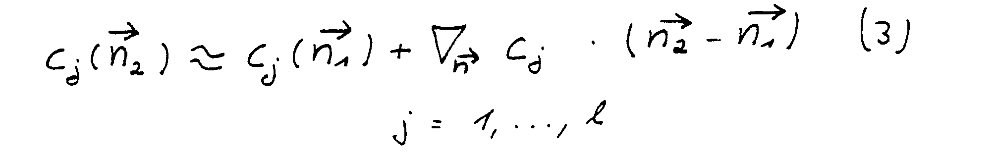
- Wertet man die Nebenbedingungen an der Stelle n, aus, so erhält man den Residuenvektor mit den Komponenten bj = cj (
n1 ) - Cjo (4) Cjo: Sollwert der gewünschten Eigenschaft. - Man führt weiter eine Matrix M ein, die in ihren Zeilen die Gradienten der Nebenbedingungen enthält, und formuliert damit die Forderung an den Vektor

n bezüglich der L2-Norm minimal sein soll. Daher gilt mitα als dem die Lagrange-Multiplikatoren enthaltenden Vektor:
α = (MMT)-1 2b (7) was mittels dses Householderverfahrens berechnet wird. Man erhält damit Δn = - MT(MMT)-1 b (8) - Im allgemeinen erreicht man den zulässigen Bereich nach wenigen Iterationsschritten dieser Art.
- Für dieses Verfahren vom Newton-Typ sind Berechnungen physikalischer Eigenschaften aus dem Brechzahlprofil erforderlich, des weiteren die Berechnungen der Ableitungen der diese Eigenschaften verkörpernden mathematischen Funktionen nach den Brechzahlen der einzelnen Schichten.
- 1.) Die chromatische Dispersion wird durch numerische Differentiation der Gruppenlaufzeit berechnet, wobei Modenfeld und -ausbreitungskonstante numerisch bestimmt werden, z.B. nach U.Fotheringham, D.Krause, R.Kunstmann, "Calculations to Determine the Effective Cutoff Wavelength of Single-Mode Fibers", JOpt.Commun.8, 4, pp.143-147, 1987, und A.W.Snyder, J.d.Love, "Optical Waveguide Theory", London. New York: Chapman and Hall, 1983".
- Bei der Berechnung des Gradienten der chromatischen Dispersion geht man von der Störungskorrektur erster Ordnung, die sich für die longitudinale Ausbreitungskonstante β im Falle des Übergangs
n →n + Δn ergibt, aus. In Integralschreibweise erhält man:

- Für die chromatische Dispersion gilt:

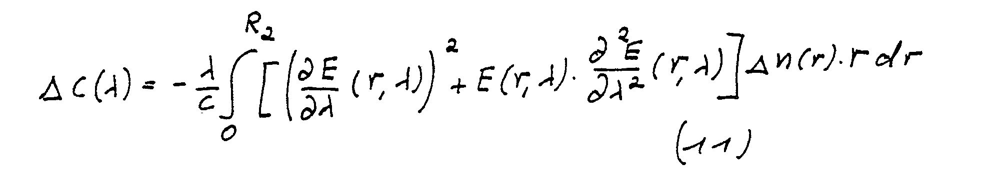
- Die Brechzahlprofiländerung A n(r) wird dabei als wellenlängenunabhängig angenommen, nicht jedoch das Ausgangsbrechzahlprofil, das für jede Wellenlänge neu aus dem Konzentrationsprofil der Dotiermaterialien berechnet wird. Dieses Konzentrationsprofil wird seinerseits bei jedem Interationsschritt neu errechnet. Es ergibt sich also für den Gradienten:

- 2.) Die Dämpfung des LP01- und des LP11-Modes wird nach der schon genannten Arbeit von Fotheringham et al berechnet. Dort wird der Verlust pro Länge mit

- Die wesentliche spektrale Abhängigkeit dieses Dämpfungsausdruckes ist im Verhältnis der Amplitudenquadrate enthalten. Bei der Bildung des Gradienten werden daher Ro und R1 sowie β als in guter Näherung konstant angesehen, so daß nur die Ableitungen des Feldes an der Stelle R1 nach den einzelnen Brechzahlen benötigt werden. Um diese zu erlangen, wird die skalare Wellengleichung differenziert und damit eine inhomogene Differentialgleichung für die gesuchte Ableitung der Feldfunktion erhalten:

- Alle auftretenden Differentialquotienten sind dabei als Differenzenquotienten zu verstehen. Zur Lösung verwendet man die Methode der Variation der Konstanten, da man so durch Ausnutzung von Rechenvorteilen alle m Ableitungsfunktionen mit einem Schritt erhalten kann.
- Die Dämpfungsberechnungen dienen der Festlegung der Grundmodendämpfung (s. oben c)) und der Festlegung der Obermodendämpfung (Obermodencutoff, s. oben b)).
- 3.) Für den Modenfelddurchmesser wo wird hier die I/e-Definition verwendet, d.h., es gilt E(wo)/E(0) = l/e. Durch eine Veränderung der Brechzahl nk geht wo über in wo + Δ wo, und es gilt in erster Näherung:


- Im folgenden wird jetzt die Minimumsuche mit der Methode des projizierten Gradienten beschrieben: Da die zu minimierende Funktion in der vorliegenden Form


- Man geht sodann nach einer Art PrädiktoriKorrektor-Verfahren vor, indem man längs der Richtung des negativen projizierten Gradienten
- Im folgenden wird der Gang des Verfahrens anhand der beigefügten Figuren erläutert.
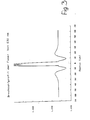
- Fig. 1 zeigt gewünschte Werte (markiert (s.a)) der chromatischen Dispersion der Faser bei verschiedenen Wellenlängen sowie einen damit übereinstimmenden gewünschten Verlauf der Dispersionskurve, der auch tatsächlich erzielt wird.
- Fig. 2 zeigt das der Rechnung zugrundegelegte Startprofil.
- Fig. 3 zeigt das sich nach dem ersten Schritt der Rechnung in Richtung auf den zulässigen Brechzahlbereich (den Bereich derjenigen Brechzahlen, mit denen die gewünschten Eigenschaften erzielt werden können) ergebende Brechzahlprofil.
- Fig. 4 zeigt das nach weiteren Rechenschritten erhaltene erste Brechzahlprofil, das in dem zulässigen Brechzahlbereich liegt.
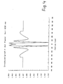
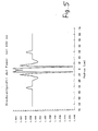
- Fig. 5 und 6 zeigen Brechzahlprofilenach einigen (z.B. 5) bzw. vielen (z.B. 15) Näherungsschritten längs des projizierten Gradienten in Richtung auf das Minimum.
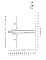
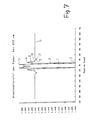
- Fig. 7 zeigt das endgültig errechnete Brechzahlprofil.
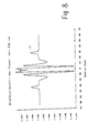
- Fig. 8 zeigt ein weiter modifiziertes Brechzahlprofil.
- Die in Fig. 1 dargestellte Kurve bezieht sich auf das Profil aus Abb. 5. Es sei darauf hingewiesen, daß die Brechzahlen in 1/10 um-Abständen vom Radius Null bis zum Radius 35 um variiert wurden.
- Man erhält gem. Fig. 7 ein Brechzahlprofil nach Art desjenigen einer Vielschichtfaser. Das Profil weist längs des Radius eine charakteristische Folge fast dreieckiger Hebungen und Senkungen des Brechzahlniveaus mit dazwischen liegenden flachen Zonen auf, wobei sich bekannte Grobstrukturen, nämlich ein auf den Kern 1 relativ hoher Brechzahl folgendes erstes, stark ausgeprägtes Brechzahlminimum 2, ein darauf folgendes ausgeprägtes erstes Brechzahlmaximum 4, ein schwaches zweites Minimum 5 und ein Auslaufbereich 6 wiederfinden (EP-OS 0 224 282).
- Im Vergleich zu bekannten Brechzahlprofilen, z.B. nach der schon erwähnten EP-OS 0 224 282, liegen wesentliche Veränderungen vor:
- Bei einfachen Fasern, d.h. solchen mit einer einzigen Stufe im Brechzahlprofil, kann die einzige Nullstelle der chromatischen Dispersion noch unterhalb 1.300 nm liegen. Bei bekannten TC (Triple-Clad) und QC (Quadrupel-Clad)-Strukturen wird durch zusätzliche Brechzahlstufen der Verlauf der chromatischen Dispersion im langwelligen Bereich nach unten gebogen, so daß man zwei Nullstellen der chromatischen Dispersion erhält, wobei die erste Nullstelle im Vergleich zur einfachen Faser auf einen Wert oberhalb 1.300 nm verschoben ist. Wenn man die erste Nullstelle bei 1.300 nm haben möchte, muß also die chromatische Dispersion bei 1.300 nm auf Null angehoben werden. Dies ist bei der erfindungsgemäßen Faser erreicht, und zwar dadurch, daß am Außenrand des Kerns 1 ein zweites Maximum 7 der Brechzahl vorgesehen ist, das durch die steil ausgeführte Abstiegsflanke 3 mit dem ersten Minimum 2 verbunden ist. Im Kern steigt die Brechzahl zu dem zweiten maximum 7 hin in einer konkaven Kurve an.
- Weiterhin kann der in Fig. 4 allmähliche Abfall der Brechzahl vom ersten Brechzahlmaximum 4 zu dem zweiten Brechzahlminimum 5 wirtschaftlicher gestaltet werden, wenn man ihn stufenförmig vornimmt und dabei eine Stufe auf dem Niveau des Matrixmaterials hält. Es werden also mehrere Wendepunkte, z.B. 8, 9, 10, dort vorgesehen.
- Wie Fig. 7 zeigt, liegt das erste Brechzahlminimum 2 verhältnismäßig tief. Dies kann technische Schwierigkeiten bereiten. Es ist deshalb meist zweckmäßig, in den Rechengang als gewünschte Eigenschaft einen nicht zu unterschreitenden Tiefstwert der Brechzahl einzuführen. Dies kann in der Rechnung dadurch berücksichtigt werden, daß man in die oben angeführte Norm untere Brechzahlbarrieren nach Art von "penalty"-Funktionen einführt. Die Rechnung liefert dann im Ergebnis ein natürliches Brechzahlprofil, das im Auslaufbereich 6 ein drittes Brechzahlmaximum 11 hat. Ein derartiges Brechzahlprofil ist in Fig. 8 dargestellt. Das dritte Maximum 11 bewirkt eine Erhöhung der Tunnelwahrscheinlichkeit für die LP11-Photonen aus der Kernzone in das die Faser umgebende Material und damit eine günstige Beeinflussung des Obermodencutoffs, d.h. eine Erhöhung der Obermodendämpfung.
- So werden Felddurchmesser möglich, die so breite Kernstrukturen verlangen, daß normalerweise der effektive Obermodencutoff über 1.300 nm hinaus nach oben verschoben würde. Das dritte Maximum 11 liegt so weit außen, daß es den Grundmode (d.h. dessen Dämpfung und Dispersion) nicht mehr stört. Das dritte Maximum hatte sich auch bei dem Rechengang ohne Festlegung eines Brechzahl-Tiefstwertes schon frühzeitig eingestellt, wie aus Fig. 4 zu ersehen ist. Es war aber auf dem Weg längs des projizierten Gradienten wieder verschwunden.
- Die vorliegende Erfindung wurde im Rahmen einer Promotionsarbeit an der Johannes-Gutenberg-Universität Mainz, Fachbereich Physik, gemacht.
Claims (18)


Applications Claiming Priority (2)
| Application Number | Priority Date | Filing Date | Title |
|---|---|---|---|
| DE3812140 | 1988-04-12 | ||
| DE3812140A DE3812140A1 (de) | 1988-04-12 | 1988-04-12 | Monomode-lichtleitfaser |
Publications (2)
| Publication Number | Publication Date |
|---|---|
| EP0341427A2 true EP0341427A2 (de) | 1989-11-15 |
| EP0341427A3 EP0341427A3 (de) | 1991-02-27 |
Family
ID=6351811
Family Applications (1)
| Application Number | Title | Priority Date | Filing Date |
|---|---|---|---|
| EP19890106144 Withdrawn EP0341427A3 (de) | 1988-04-12 | 1989-04-07 | Monomode-Lichtleitfaser und Verfahren zu deren Herstellung |
Country Status (4)
| Country | Link |
|---|---|
| US (1) | US5013131A (de) |
| EP (1) | EP0341427A3 (de) |
| JP (1) | JPH0271204A (de) |
| DE (1) | DE3812140A1 (de) |
Cited By (4)
| Publication number | Priority date | Publication date | Assignee | Title |
|---|---|---|---|---|
| EP0414369A3 (en) * | 1989-07-17 | 1991-03-06 | Minnesota Mining And Manufacturing Company | Single-mode, single-polarization optical fiber |
| FR2736440A1 (fr) * | 1995-07-07 | 1997-01-10 | Alcatel Submarcom | Guide optique monomode a dispersion decalee et grande surface effective de mode |
| FR2782391A1 (fr) * | 1998-08-13 | 2000-02-18 | Alsthom Cge Alcatel | Ajout d'un anneau externe au profil d'indice d'une fibre optique monomode a dispersion decalee |
| FR2782392A1 (fr) * | 1999-08-23 | 2000-02-18 | Cit Alcatel | Fibre optique monomode a dispersion decalee comprenant un anneau exterieur |
Families Citing this family (23)
| Publication number | Priority date | Publication date | Assignee | Title |
|---|---|---|---|---|
| EP0413387A1 (de) * | 1989-08-16 | 1991-02-20 | Koninklijke Philips Electronics N.V. | Polarisationshaltige einwellige optische Faser |
| DE4001781C1 (de) * | 1990-01-23 | 1991-02-21 | Schott Glaswerke, 6500 Mainz, De | |
| US5361319A (en) * | 1992-02-04 | 1994-11-01 | Corning Incorporated | Dispersion compensating devices and systems |
| FR2724234B1 (fr) | 1994-09-05 | 1997-01-03 | Alcatel Fibres Optiques | Fibre optique monomode a dispersion decalee |
| CA2157828C (en) * | 1994-09-13 | 2003-02-11 | Youichi Akasaka | Dispersion compensating optical fiber for wavelength division multiplex transmission |
| US5553185A (en) * | 1994-12-27 | 1996-09-03 | Corning Incorporated | Controlled dispersion optical waveguide |
| US5835655A (en) | 1995-01-26 | 1998-11-10 | Corning Incorporated | Large effective area waveguide fiber |
| US6018533A (en) * | 1995-04-21 | 2000-01-25 | Ceramoptec Industries, Inc. | Optical fiber and integrated optic lasers with enhanced output power |
| US5822488A (en) * | 1995-10-04 | 1998-10-13 | Sumitomo Electric Industries, Inc. | Single-mode optical fiber with plural core portions |
| US5715346A (en) * | 1995-12-15 | 1998-02-03 | Corning Incorporated | Large effective area single mode optical waveguide |
| JPH1033549A (ja) * | 1996-07-24 | 1998-02-10 | Shinji Kokubu | レーザプローブ |
| WO1999012064A1 (en) * | 1997-08-28 | 1999-03-11 | Sumitomo Electric Industries, Ltd. | Dispersion shift fiber |
| EP1061055A4 (de) * | 1998-02-03 | 2006-11-15 | Sumitomo Electric Industries | Verfahren zur herstellung von grundstoffen für optische fasern |
| KR100636332B1 (ko) * | 1998-09-21 | 2006-10-19 | 피렐리 카비 에 시스테미 소시에떼 퍼 아찌오니 | 확장 파장 밴드용의 광파이버 |
| US6292612B1 (en) * | 1999-06-07 | 2001-09-18 | Lucent Technologies Inc. | Multi-mode optical fiber having improved refractive index profile and devices comprising same |
| KR20010101087A (ko) * | 1999-10-22 | 2001-11-14 | 야마모토 토요미쯔 | 광학 감쇠기 |
| CN1391657A (zh) * | 1999-11-22 | 2003-01-15 | 康宁股份有限公司 | 有效面积大的色散位移波导光纤 |
| US7027698B2 (en) * | 2000-03-03 | 2006-04-11 | Pirelli Cavi E Sistemi S.P.A. | Optical fiber for WDM transmission |
| JP3753975B2 (ja) * | 2001-11-29 | 2006-03-08 | 株式会社フジクラ | シングルモード光ファイバの製造方法及びシングルモード光ファイバ |
| US20040159124A1 (en) * | 2003-02-14 | 2004-08-19 | Atkins Robert M. | Optical fiber manufacture |
| US7003203B2 (en) * | 2003-07-18 | 2006-02-21 | Corning Incorporated | Large effective area, low kappa, dispersion compensating optical fiber and telecommunication span including same |
| US8107784B2 (en) * | 2007-06-15 | 2012-01-31 | Ofs Fitel, Llc | Reduced bend sensitivity and catastrophic bend loss in single mode optical fibers and method of making same |
| US8369672B2 (en) * | 2010-04-27 | 2013-02-05 | Verrillon, Inc. | Single-polarization fiber |
Family Cites Families (13)
| Publication number | Priority date | Publication date | Assignee | Title |
|---|---|---|---|---|
| US4149772A (en) * | 1975-09-22 | 1979-04-17 | Northern Electric Company Limited | Optical fibre having low mode dispersion |
| US4439007A (en) * | 1981-06-09 | 1984-03-27 | Bell Telephone Laboratories, Incorporated | Low dispersion single mode fiber |
| US4435040A (en) * | 1981-09-03 | 1984-03-06 | Bell Telephone Laboratories, Incorporated | Double-clad optical fiberguide |
| US4412722A (en) * | 1981-10-26 | 1983-11-01 | Western Electric | Single mode fiber with graded index of refraction |
| US4715679A (en) * | 1981-12-07 | 1987-12-29 | Corning Glass Works | Low dispersion, low-loss single-mode optical waveguide |
| CA1248386A (en) * | 1982-03-11 | 1989-01-10 | Leonard G. Cohen | Quadruple-clad optical fiberguide |
| DE3376884D1 (de) * | 1983-06-29 | 1988-07-07 | Ant Nachrichtentech | Single-mode w-fibre |
| JPS6252508A (ja) * | 1985-09-02 | 1987-03-07 | Nippon Telegr & Teleph Corp <Ntt> | 光フアイバ |
| NL8502625A (nl) * | 1985-09-26 | 1987-04-16 | Philips Nv | Optisch transmissiesysteem bevattende een stralingsbron en een meervoudig beklede monomode optische transmissievezel met een negatieve stap in het brekingsindexprofiel. |
| US4852968A (en) * | 1986-08-08 | 1989-08-01 | American Telephone And Telegraph Company, At&T Bell Laboratories | Optical fiber comprising a refractive index trench |
| US4770492A (en) * | 1986-10-28 | 1988-09-13 | Spectran Corporation | Pressure or strain sensitive optical fiber |
| US4893896A (en) * | 1987-07-10 | 1990-01-16 | Mitsubishi Cable Industries, Ltd. | Energy transmission optical fiber |
| US4919504A (en) * | 1989-05-17 | 1990-04-24 | Bell Communications Research, Inc. | Graded-index waveguides |
-
1988
- 1988-04-12 DE DE3812140A patent/DE3812140A1/de active Granted
-
1989
- 1989-04-07 EP EP19890106144 patent/EP0341427A3/de not_active Withdrawn
- 1989-04-12 JP JP1092805A patent/JPH0271204A/ja active Pending
- 1989-04-12 US US07/337,205 patent/US5013131A/en not_active Expired - Fee Related
Cited By (12)
| Publication number | Priority date | Publication date | Assignee | Title |
|---|---|---|---|---|
| EP0414369A3 (en) * | 1989-07-17 | 1991-03-06 | Minnesota Mining And Manufacturing Company | Single-mode, single-polarization optical fiber |
| FR2736440A1 (fr) * | 1995-07-07 | 1997-01-10 | Alcatel Submarcom | Guide optique monomode a dispersion decalee et grande surface effective de mode |
| EP0753771A3 (de) * | 1995-07-07 | 1997-01-22 | Alcatel Submarcom | Monomodaler dispersionsverschobener optischer Wellenleiter mit grosser effektiver Modenfläche |
| US5675690A (en) * | 1995-07-07 | 1997-10-07 | Alcatel Submarcom | Dispersion-flattened single-mode optical waveguide with large effective mode surface area |
| FR2782391A1 (fr) * | 1998-08-13 | 2000-02-18 | Alsthom Cge Alcatel | Ajout d'un anneau externe au profil d'indice d'une fibre optique monomode a dispersion decalee |
| WO2000010043A1 (fr) * | 1998-08-13 | 2000-02-24 | Alcatel | Fibre optique monomode a dispersion decalee comprenant un anneau exterieur de l'indice de refraction |
| WO2000010042A1 (fr) * | 1998-08-13 | 2000-02-24 | Alcatel | Fibre optique monomode a dispersion decalee avec anneau exterieur de l'indice de refraction |
| EP0984309A1 (de) * | 1998-08-13 | 2000-03-08 | Alcatel | Dispersionsverschobene optische Einmodenfaser mit einem äusseren Brechzahl-Ring |
| EP0984308A1 (de) * | 1998-08-13 | 2000-03-08 | Alcatel | Dispersionsverschobene optische Einmodenfaser mit einem äusseren Brechzahl-Ring |
| US6363196B1 (en) | 1998-08-13 | 2002-03-26 | Alcatel | Single mode dispersion-shifted optical fiber with external refractive index ring |
| US6424775B1 (en) | 1998-08-13 | 2002-07-23 | Alcatel | Single mode dispersion-shifted optical fiber comprising an external refractive index ring |
| FR2782392A1 (fr) * | 1999-08-23 | 2000-02-18 | Cit Alcatel | Fibre optique monomode a dispersion decalee comprenant un anneau exterieur |
Also Published As
| Publication number | Publication date |
|---|---|
| DE3812140A1 (de) | 1989-11-02 |
| JPH0271204A (ja) | 1990-03-09 |
| US5013131A (en) | 1991-05-07 |
| DE3812140C2 (de) | 1990-04-26 |
| EP0341427A3 (de) | 1991-02-27 |
Similar Documents
| Publication | Publication Date | Title |
|---|---|---|
| DE3812140C2 (de) | ||
| DE3232194C2 (de) | ||
| DE60037365T2 (de) | Dispersionkompensierende optische Faser | |
| DE102011009242B4 (de) | Lichtwellenleiter und Halbzeug zur Herstellung eines Lichtwellenleiters mit biegeoptimierten Eigenschaften | |
| DE3312698C2 (de) | Monomode-Faser | |
| DE3307874C2 (de) | ||
| DE3221836C2 (de) | Einzelmodenfaser | |
| EP0191202B1 (de) | Lichtleitfaser mit Fluordotierung und Verfahren zu deren Herstellung | |
| EP0474986A1 (de) | Verfahren zur Herstellung von Glasfaser-Lichtwellenleitern mit erhöhter Zugfestigkeit | |
| DE2533144A1 (de) | Optisches faser-uebertragungsmedium | |
| DE69519192T2 (de) | Faseroptischer Koppler mit niedrigem nichtadiabatischem Verlust | |
| EP0438653B1 (de) | Flexible optische Gradientenprofilfaser zur Übertragung von Laserstrahlung mit hoher Leistung bei weitgehender Erhaltung der Modenstruktur | |
| DE19505929C1 (de) | Optisches Bauteil | |
| DE69216366T2 (de) | Glasfaser für hohe Eingangsleistung und Herstellungsverfahren dafür | |
| DE2907650C3 (de) | Multimode-Lichtleiter | |
| DE69311168T2 (de) | Optische Faser zum Anschluss an einen Wellenleiter und Verfahren zu ihrer Herstellung | |
| EP0327702B1 (de) | Lichtwellenleiter | |
| DE19928971A1 (de) | Mehrfachmantellichtleiter, dort eingeschriebenes Langperiodenlichtleitergitter, und zugehöriges Einschreibeverfahren | |
| DE60209457T2 (de) | Optische Stufenindexfaser mit dotiertem Kern und Mantel, Vorform und Herstellungsverfahren fÜr eine solche Faser | |
| DE69900319T2 (de) | Verfahren zur Aussenabscheidung von dotiertem Quarz auf einer Vorform für optische Fasern | |
| DE69830547T2 (de) | Mehrkernfaser | |
| DE3201342C2 (de) | Optische Faser für Einmodenwelle mit einer einzigen Polarisation und Verfahren zu ihrer Herstellung | |
| EP2933238B1 (de) | Herstellungsverfahren für eine vorform für einen lichtwellenleiter mit einem nicht-runden kern und einem dotierten mantelbereich mit vorgegebener numerischer apertur | |
| EP0413387A1 (de) | Polarisationshaltige einwellige optische Faser | |
| EP0198118B1 (de) | Einwelliger Lichtwellenleiter aus Quarzglas und Verfahren zu dessen Herstellung |
Legal Events
| Date | Code | Title | Description |
|---|---|---|---|
| PUAI | Public reference made under article 153(3) epc to a published international application that has entered the european phase |
Free format text: ORIGINAL CODE: 0009012 |
|
| AK | Designated contracting states |
Kind code of ref document: A2 Designated state(s): AT BE CH DE ES FR GB GR IT LI LU NL SE |
|
| RBV | Designated contracting states (corrected) |
Designated state(s): DE FR GB NL |
|
| RBV | Designated contracting states (corrected) |
Designated state(s): DE FR GB NL |
|
| PUAL | Search report despatched |
Free format text: ORIGINAL CODE: 0009013 |
|
| 17P | Request for examination filed |
Effective date: 19901219 |
|
| AK | Designated contracting states |
Kind code of ref document: A3 Designated state(s): AT BE CH DE ES FR GB GR IT LI LU NL SE |
|
| 17Q | First examination report despatched |
Effective date: 19921214 |
|
| RAP1 | Party data changed (applicant data changed or rights of an application transferred) |
Owner name: SCHOTT GLASWERKE Owner name: CARL-ZEISS-STIFTUNG TRADING AS SCHOTT GLASWERKE |
|
| STAA | Information on the status of an ep patent application or granted ep patent |
Free format text: STATUS: THE APPLICATION IS DEEMED TO BE WITHDRAWN |
|
| 18D | Application deemed to be withdrawn |
Effective date: 19940506 |