EP0341208A1 - Motorisierter Rumpf, aufgehängt unter einem Tragflügel - Google Patents
Motorisierter Rumpf, aufgehängt unter einem Tragflügel Download PDFInfo
- Publication number
- EP0341208A1 EP0341208A1 EP89810316A EP89810316A EP0341208A1 EP 0341208 A1 EP0341208 A1 EP 0341208A1 EP 89810316 A EP89810316 A EP 89810316A EP 89810316 A EP89810316 A EP 89810316A EP 0341208 A1 EP0341208 A1 EP 0341208A1
- Authority
- EP
- European Patent Office
- Prior art keywords
- fuselage
- pilot
- hull
- propeller
- suspension
- Prior art date
- Legal status (The legal status is an assumption and is not a legal conclusion. Google has not performed a legal analysis and makes no representation as to the accuracy of the status listed.)
- Withdrawn
Links
- 230000005484 gravity Effects 0.000 claims abstract description 10
- 239000000725 suspension Substances 0.000 claims description 23
- 230000005540 biological transmission Effects 0.000 claims description 7
- 230000033001 locomotion Effects 0.000 claims description 2
- 238000010276 construction Methods 0.000 description 4
- 210000002414 leg Anatomy 0.000 description 4
- 230000002349 favourable effect Effects 0.000 description 3
- 230000001681 protective effect Effects 0.000 description 2
- 238000006243 chemical reaction Methods 0.000 description 1
- 238000001816 cooling Methods 0.000 description 1
- 238000006073 displacement reaction Methods 0.000 description 1
- 230000000694 effects Effects 0.000 description 1
- 239000002828 fuel tank Substances 0.000 description 1
- 239000003365 glass fiber Substances 0.000 description 1
- 210000000056 organ Anatomy 0.000 description 1
- 230000035515 penetration Effects 0.000 description 1
- 229920000728 polyester Polymers 0.000 description 1
- 229920002994 synthetic fiber Polymers 0.000 description 1
- 239000004753 textile Substances 0.000 description 1
- 210000000689 upper leg Anatomy 0.000 description 1
Images

Classifications
-
- B—PERFORMING OPERATIONS; TRANSPORTING
- B64—AIRCRAFT; AVIATION; COSMONAUTICS
- B64C—AEROPLANES; HELICOPTERS
- B64C31/00—Aircraft intended to be sustained without power plant; Powered hang-glider-type aircraft; Microlight-type aircraft
- B64C31/028—Hang-glider-type aircraft; Microlight-type aircraft
Definitions
- the present invention relates to a motorized fuselage for locomotion in the air, arranged to be suspended from an airfoil to form an ultra-light motorized device usable for motorized flight and for gliding flight,
- the fuselage comprising an elongated aerodynamic hull containing a space for a pilot, the fuselage further comprising means for suspending the airfoil, a motor disposed in the hull in front of the suspension means, and a propeller disposed at the rear and provided with a shaft connected to the motor by transmission means, the propeller comprising a propulsion position for motorized flight and a space-saving stop position in particular for gliding flight, and the hull offering the pilot a standing position for take-off and a lying position for flight and comprising at least one lower opening for the passage of the pilot's legs in a standing position.
- ULM ultra-light motorized flying device
- the articulated frame can be folded forward in the hull, the two propeller blades then having to be oriented parallel to the hull to retract there. Thanks to the placement of the engine at the front, the center of gravity of the fuselage is close to that of the pilot and to the vertical passing through the point of suspension to the wing, so that the pilot can easily take off while running and carrying the wing and the fuselage, then be lifted by the latter without the fuselage trim.
- a particularly light fuselage is thus obtained, which can be devoid of wheels and provided with simple landing skids, and which does not require auxiliary carriage or other similar means for take-off.
- Patent application DE-A-3'440'823 shows a motorized nacelle which is intended to be suspended from a hang-glider and which does not have an articulated frame for the propeller, the latter being mounted in a stationary position at l rear of the basket.
- gliding flight its aerodynamics are relatively poor, because the pilot is simply lying on the nacelle which does not form a real hull enveloping his body, and because the drag of the stopped propeller is too great.
- the size of the propeller requires a fixed stand under the rear of the fuselage and a running gear on the trapeze bar for take-off and landing.
- Patent application FR-A-2,543,512 describes an ULM device capable of gliding, but devoid of fuselage.
- a propeller unit with a propeller with folding blades is suspended from the keel of a hang glider, in a longitudinal position which changes from one flight phase to another.
- the pilot is much lower than this group and is suspended from the hang glider in the conventional manner, by means of a harness. Takeoff is done using a special trolley. This device is therefore not very advantageous as regards aerodynamics and ease of use.
- the present invention aims to avoid the aforementioned drawbacks, by providing a motorized fuselage of the type indicated in the preamble, having a low drag as well in gliding flight as in motorized flight while avoiding the use of the hinged articulated chassis mentioned above. above, the fuselage being nevertheless well balanced with respect to its point of suspension to the wing and with respect to the position of the pilot, so as to allow the pilot to take off easily in standing position while carrying the fuselage.
- the rear part of the hull can advantageously be equipped with a folding propeller protection member, this member having a position deployed towards the ground, in which it extends lower than the propeller in position. propulsion, and a folded position against or in the hull.
- said place of the pilot is such that the center of gravity of the pilot is located near a vertical passing through the center of gravity of the fuselage, which makes it possible to maintain constant the attitude of the aircraft, particularly during takeoff.
- the fuselage can then be fitted with suspension members on the pilot's shoulders.
- a particularly convenient embodiment consists in that the fuselage comprises a tilting berth for the pilot's torso, and in that this berth is articulated to the fuselage at the pilot's hips.
- the tilting berth is removably attached to the fuselage at its articulation, and said suspension members on the pilot's shoulders are fixed to the tilting berth, which allows the pilot to equip himself with the berth first. , then suspend the fuselage while standing.
- the pilot in said prone position, is lying head forward and the engine is placed below the pilot's head and / or torso.
- the transmission means may include a longitudinal shaft which passes between the legs of the pilot in a standing position.
- the fuselage according to the invention can be used with different wings, thanks to suitable suspension means.
- the suspension means comprise at least three flexible hangers, the lower ends of which are fixed to the hull, and the upper ends of which are attached to a common attachment member for suspending the fuselage from a hang glider, such as the usual pendulum suspension of a pilot practicing free flight.
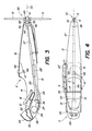
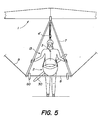
- the example of apparatus illustrated in figs. 1, 2 and 5 consists of a classic hang-glider 1 (also called free flight wing) and a motorized fuselage 2 according to the invention, the fuselage being suspended from the hang-glider by means of two pairs of flexible hangers 3, the lower ends are hooked to lateral heads 4 for supporting the fuselage, while their upper ends are assembled and hooked together by a carabiner 4 ′ to a conventional suspension loop 5 fixed to the structure 6 of the hang glider.
- This structure also includes a well-known control member, commonly called the trapezoid, formed by two oblique bars 7, the lower ends of which are connected together by a transverse bar 8 and at the ends of the hang-glider by cables 9 and 10.
- the two rear lateral lines 3 can be replaced by a single rear line located in the median plane.
- This can be fitted with an electric circuit breaker which stops the engine when the line relaxes, in order to prevent the deployed propeller from touching hang glider 1 if the rear of the fuselage comes close to it, especially in disturbed flight conditions.
- This rear hanger could also be replaced by a rigid arm.
- the fuselage 2 the construction of which is more particularly visible in FIGS. 3 and 4, comprises a light and rigid shell 12 of aerodynamic shape, made for example of polyester reinforced with glass fibers.
- This hull has a tapered shape in which a pilot 13 can take place in the prone lying position without his body emerging substantially outside the hull.
- this set has good air penetration characteristics which, for gliding, are as favorable as those of a classic hang-glider pilot, enclosed in a flexible cocoon.
- the shell 12 is provided with an upper opening 14 and a lower opening 15 which are partially superimposed at least in the zone of the center of gravity G of the fuselage, to allow the pilot 13 to stand upright in this area, as shown in fig. 2.
- a tilting berth 16 (removed on the fig. 4 for clarity of the drawing) which is pivotally and removably mounted, for example on a crossbar 17 secured to the hull at the pilot's hips.
- this berth is provided with straps 18 (fig. 2) allowing the fuselage to be suspended from the shoulders of the pilot when the latter is standing.
- the pilot can attach the berth 16 to the torso, before placing himself in the fuselage and hooking the latter to the berth.
- the hull 12 has a transverse structure 20 which in particular forms a cell 21 for a reserve parachute and a cell 22 for instruments 23 exposed to the eyes of the pilot, behind a profiled windshield 24 of synthetic material transparent. Depending on the case, these cells could be provided laterally or removed to reduce the height of the hull.
- a propeller 30 with folding blades 31 is carried by a rotary shaft 32 rises in a stationary position at the rear of the fuselage 2, so that the direction of the axis of rotation 33 of the propeller corresponds to the desired direction of thrust .
- the shaft 32 is mounted by a bearing 34 in a rear wall 35 of the shell 12.
- the motor 26 is connected to the shaft 32 by a reduction box 36, driving a tubular transmission shaft 37 provided with a seal d hinge 38 at the rear and protected by a fixed tube 39 which extends between the legs of the pilot.
- the seal 38 is provided to allow an inclination of the shaft 37 relative to the axis 33 of the propeller, but it is not necessary in all cases.
- the axis 33 of the propeller can be in the extension of the transmission shaft if the latter is not too inclined.
- the propeller 30 has two blades 31 each mounted by an articulation 40 on a hub 41 integral with the shaft 32, this articulation containing a spring which tends to fold the blade parallel to the axis 33 when the propeller does not rotate, in the position drawn in solid lines in FIG. 1.
- This folded position of the propeller 30, advantageously located in the extension of the hull 12, is extremely favorable for finesse in gliding flight. In addition, it prevents the blades from catching on obstacles or on the ground, for example when landing.
- the propeller can also have more than two blades.
- a folding crutch 42 is articulated at 43 under the rear part of the hull, this crutch being folded down by means of an elastic element 44 and deployed by the pilot by means of a pulling cable 45.
- a rear opening 46 is provided to receive its end in the rear of the hull.
- a different protective member can be provided in place of this crutch, for example an arch or a double crutch in inverted V ensuring stable support on the ground and protection on the sides.
- Another advantageous construction consists in replacing the tilting crutch 42 by a crutch which retracts into the hull by sliding through a small opening.
- the front end of this sliding stand can be articulated to a sleeve which slides on the tube 39. In the deployed position, its rear end can come fairly close to the circumference of the propeller and thus provide effective protection.
- the drawings also show an advantageous layout of a fuel tank 48 mounted in a central area of the hull 2, above the thighs of the pilot, and connected to the engine by a lateral pipe 49.
- This tank can have a capacity of a few liters, sufficient for one or more hours of powered flight.
- the entire fuselage 2 can be constructed so as to have a relatively modest total weight, of the order of 20 to 30 kg, to be supported by the shoulders of the pilot who is in a standing position.
- the position of the center of gravity G in the immediate vicinity of the pilot's center of gravity is enabled by the favorable distribution of the mechanical elements, with the propeller 30 at the rear and the engine 26 at the front. In some cases, a different distribution can be obtained by rejecting the reduction box 36 at the rear.
- the ULM device is designed to fly sometimes with the engine, sometimes in gliding flight. Takeoff is generally (but not necessarily) with the engine, in the position illustrated in Figure 2.
- the pilot starts the engine, lifts the hang glider 1 and the fuselage 2 and starts to run with the help of the thrust provided by the propeller, until the lift of the wing successively lifts the fuselage, then the pilot leaning on the tilting berth 16.
- the pilot then enters his legs in the hull to get into the supine position, while keeping his arms outside to control the aircraft, holding the trapeze bar in his hands 8. He folds the stand 42 by releasing the cable 45.
- the engine controls can be placed within reach on one side of the hull , which allows him, for example, to stop the engine after reaching a sufficient altitude, to make a gliding flight of a certain duration, then to restart the engine to fly longer. Landing can be done in the same way as with a traditional hang-glider, with the engine stopped, the propeller folded and the pilot in the standing position.
- the trapeze bar 8 can be equipped with a pair of rollers 50 as protection, to avoid touching the ground. This also makes it possible to land in a slide, the pilot then remaining in the supine position.
- An important advantage of the fuselage 2 described above lies in the fact that it can be used both with hang glider 1 and with a paraglider 51 (directional parachute), as shown in FIG. 6.
- a paraglider 51 directional parachute
- Such loops already exist on the paragliders, to allow the suspension of a harness carrying the pilot at the lower end of the lines 53 connected respectively to the left half and to the right half of the dome textile 54 of the paraglider.
- each loop 52a, 52b is connected to the lower end of the rear hanger 3 located on the opposite side.
- the conventional cords 55 for controlling the paraglider can be extended to pass over pulleys mounted for this purpose on each side of the hull.
- takeoff can be done safely as follows, the wing of the paraglider being placed on the ground behind the fuselage.
- the pilot By carrying the fuselage 2, the pilot begins to advance.
- the wing of the paraglider inflates and rises above the pilot, who can then start the engine to turn the propeller and take off.
- the lines 53 of the paraglider are not likely to hang on to the propeller and one can do without a protective mesh around it.
- a fuselage of this kind allows still other uses in the field of sports and entertainment, for example to propel a man standing on skis or on a vehicle such as a sled, a trolley on wheels or a boat.
- a vehicle such as a sled, a trolley on wheels or a boat.
- the immediate proximity of the centers of gravity of the fuselage and the pilot is an essential advantage for the ease of use of the aircraft.
Landscapes
- Engineering & Computer Science (AREA)
- Aviation & Aerospace Engineering (AREA)
- Toys (AREA)
Applications Claiming Priority (2)
| Application Number | Priority Date | Filing Date | Title |
|---|---|---|---|
| FR8805842A FR2630704B1 (fr) | 1988-04-27 | 1988-04-27 | Fuselage motorise agence pour etre suspendu a une voilure |
| FR8805842 | 1988-04-27 |
Publications (1)
| Publication Number | Publication Date |
|---|---|
| EP0341208A1 true EP0341208A1 (de) | 1989-11-08 |
Family
ID=9365883
Family Applications (1)
| Application Number | Title | Priority Date | Filing Date |
|---|---|---|---|
| EP89810316A Withdrawn EP0341208A1 (de) | 1988-04-27 | 1989-04-27 | Motorisierter Rumpf, aufgehängt unter einem Tragflügel |
Country Status (2)
| Country | Link |
|---|---|
| EP (1) | EP0341208A1 (de) |
| FR (1) | FR2630704B1 (de) |
Cited By (6)
| Publication number | Priority date | Publication date | Assignee | Title |
|---|---|---|---|---|
| FR2668116A1 (fr) * | 1990-10-23 | 1992-04-24 | Cros Michel | Perfectionnement d'aeronefs ultralegers ou hyperlegers quant au cockpit et a la propulsion. |
| CN101033005B (zh) * | 2007-04-11 | 2010-07-21 | 谭大刚 | 悬挂式滑翔翼人力飞行驱动装置及其地面模拟训练架 |
| GB2467137A (en) * | 2009-01-22 | 2010-07-28 | Rupert John Bickham Sweet-Escott | Folding propeller guard for an aircraft |
| DE102013000461A1 (de) * | 2013-01-14 | 2014-07-31 | Michael Heger | Universelle Antriebsvorrichtung für Gleitschirme |
| RU2547122C2 (ru) * | 2014-02-19 | 2015-04-10 | Николай Валерьевич Чистяков | Устройство аварийного спасения дистанционно пилотируемого летательного аппарата |
| WO2023159304A1 (en) * | 2022-02-25 | 2023-08-31 | Bard Maurice Rheal | Personal flying apparatus incorporating a harness and method of facilitating human flight |
Families Citing this family (1)
| Publication number | Priority date | Publication date | Assignee | Title |
|---|---|---|---|---|
| CH700620A2 (fr) * | 2009-03-30 | 2010-09-30 | Andre Lecoultre | Appareil ultraleger motorise. |
Citations (4)
| Publication number | Priority date | Publication date | Assignee | Title |
|---|---|---|---|---|
| FR2543512A1 (fr) * | 1983-03-30 | 1984-10-05 | Rousseau Yves | Dispositif de propulsion notamment pour aeronefs du genre aile libre, ainsi que les aeronefs equipes de ce dispositif |
| GB2141985A (en) * | 1983-06-23 | 1985-01-09 | Sweet Escott Rupert John Bickh | A propulsion unit for an aircraft |
| DE3440823A1 (de) * | 1984-11-08 | 1986-05-15 | Hajo 5100 Aachen Harms | Ultraleichtflugzeuggondel fuer flugdrachen |
| WO1986007329A1 (fr) * | 1985-06-13 | 1986-12-18 | Lecoultre Andre | Appareil volant ultra-leger motorise a helice rabattable |
-
1988
- 1988-04-27 FR FR8805842A patent/FR2630704B1/fr not_active Expired - Fee Related
-
1989
- 1989-04-27 EP EP89810316A patent/EP0341208A1/de not_active Withdrawn
Patent Citations (4)
| Publication number | Priority date | Publication date | Assignee | Title |
|---|---|---|---|---|
| FR2543512A1 (fr) * | 1983-03-30 | 1984-10-05 | Rousseau Yves | Dispositif de propulsion notamment pour aeronefs du genre aile libre, ainsi que les aeronefs equipes de ce dispositif |
| GB2141985A (en) * | 1983-06-23 | 1985-01-09 | Sweet Escott Rupert John Bickh | A propulsion unit for an aircraft |
| DE3440823A1 (de) * | 1984-11-08 | 1986-05-15 | Hajo 5100 Aachen Harms | Ultraleichtflugzeuggondel fuer flugdrachen |
| WO1986007329A1 (fr) * | 1985-06-13 | 1986-12-18 | Lecoultre Andre | Appareil volant ultra-leger motorise a helice rabattable |
Cited By (7)
| Publication number | Priority date | Publication date | Assignee | Title |
|---|---|---|---|---|
| FR2668116A1 (fr) * | 1990-10-23 | 1992-04-24 | Cros Michel | Perfectionnement d'aeronefs ultralegers ou hyperlegers quant au cockpit et a la propulsion. |
| CN101033005B (zh) * | 2007-04-11 | 2010-07-21 | 谭大刚 | 悬挂式滑翔翼人力飞行驱动装置及其地面模拟训练架 |
| GB2467137A (en) * | 2009-01-22 | 2010-07-28 | Rupert John Bickham Sweet-Escott | Folding propeller guard for an aircraft |
| DE102013000461A1 (de) * | 2013-01-14 | 2014-07-31 | Michael Heger | Universelle Antriebsvorrichtung für Gleitschirme |
| DE102013000461B4 (de) * | 2013-01-14 | 2020-07-02 | Michael Heger | Universelle Antriebsvorrichtung für Gleitschirme |
| RU2547122C2 (ru) * | 2014-02-19 | 2015-04-10 | Николай Валерьевич Чистяков | Устройство аварийного спасения дистанционно пилотируемого летательного аппарата |
| WO2023159304A1 (en) * | 2022-02-25 | 2023-08-31 | Bard Maurice Rheal | Personal flying apparatus incorporating a harness and method of facilitating human flight |
Also Published As
| Publication number | Publication date |
|---|---|
| FR2630704A1 (fr) | 1989-11-03 |
| FR2630704B1 (fr) | 1993-07-09 |
Similar Documents
| Publication | Publication Date | Title |
|---|---|---|
| US4071206A (en) | Portable helicopter | |
| CA3020209C (fr) | Dispositif de propulsion d'un passager | |
| EP3037349A1 (de) | Drehflügel-drohne, die mit einem zubehörteil ausgestattet ist, die sie in ein amphibienfahrzeug umwandelt | |
| FR2667568A1 (fr) | Appareil individuel de vol propulse. | |
| US20230356839A1 (en) | Special electric propulsion system to power paragliders and other small, light aircraft | |
| EP0341208A1 (de) | Motorisierter Rumpf, aufgehängt unter einem Tragflügel | |
| WO2006077315A1 (fr) | Procede de locomotion aerienne et aeronef polyvalent a aile(s) gonflable(s) utilisant deux systemes de gonflage differents | |
| CN201052838Y (zh) | 人力飞行器 | |
| FR2498554A1 (fr) | Engin de locomotion a propulsion eolienne | |
| EP2488409B1 (de) | Luftschiff | |
| FR2625969A1 (fr) | Dispositif d'augmentation de la stabilite des helicopteres embarques et poses, a train d'atterrissage tricycle, et helicoptere equipe d'un tel dispositif | |
| WO2010111800A1 (fr) | Appareil ultraleger motorise | |
| WO1993011999A1 (fr) | Dispositif de loisir sportif aerien | |
| EP0327778A1 (de) | Sitzgurtzeug bei Gleitfallschirmen | |
| EP1446323A1 (de) | Ferngesteuerte flugmaschine, insbesondere für luftbildaufnahmen | |
| EP0225346A1 (de) | Ultraleichtflugzeuge mit schwenkbarem propellerantrieb | |
| EP0575344B1 (de) | Fliegendes fahrzeug, wie motorisiertes ultraleichtes flugzeug | |
| FR3133370A1 (fr) | baquet-châssis sécurisé de paramoteur à propulsion birotor exportée arrière latérale | |
| FR2723718A1 (fr) | Aile ou voilure d'ultra leger motorise pendulaire a depliage et repliage rapide et d'encombrement reduit. | |
| FR2521098A1 (fr) | Ensemble avion et planeur remorque et procede de mise en oeuvre du planeur pendant le vol de l'avion | |
| CN223590968U (zh) | 一种具备折叠机翼结构的便携式单人低空矢量喷射飞行器 | |
| FR2543512A1 (fr) | Dispositif de propulsion notamment pour aeronefs du genre aile libre, ainsi que les aeronefs equipes de ce dispositif | |
| FR2583375A1 (fr) | Appareil volant ultra-leger motorise a helice rabattable | |
| RU2124458C1 (ru) | Ротоплан и способ управления его полетом | |
| FR2744094A1 (fr) | Planeur a propulsion eolienne |
Legal Events
| Date | Code | Title | Description |
|---|---|---|---|
| PUAI | Public reference made under article 153(3) epc to a published international application that has entered the european phase |
Free format text: ORIGINAL CODE: 0009012 |
|
| AK | Designated contracting states |
Kind code of ref document: A1 Designated state(s): AT BE CH DE ES FR GB GR IT LI LU NL SE |
|
| 17P | Request for examination filed |
Effective date: 19900423 |
|
| 17Q | First examination report despatched |
Effective date: 19910712 |
|
| STAA | Information on the status of an ep patent application or granted ep patent |
Free format text: STATUS: THE APPLICATION IS DEEMED TO BE WITHDRAWN |
|
| 18D | Application deemed to be withdrawn |
Effective date: 19911130 |