EP0341208A1 - Powered fuselage suspended below a wing - Google Patents
Powered fuselage suspended below a wing Download PDFInfo
- Publication number
- EP0341208A1 EP0341208A1 EP89810316A EP89810316A EP0341208A1 EP 0341208 A1 EP0341208 A1 EP 0341208A1 EP 89810316 A EP89810316 A EP 89810316A EP 89810316 A EP89810316 A EP 89810316A EP 0341208 A1 EP0341208 A1 EP 0341208A1
- Authority
- EP
- European Patent Office
- Prior art keywords
- fuselage
- pilot
- hull
- propeller
- suspension
- Prior art date
- Legal status (The legal status is an assumption and is not a legal conclusion. Google has not performed a legal analysis and makes no representation as to the accuracy of the status listed.)
- Withdrawn
Links
Images

Classifications
-
- B—PERFORMING OPERATIONS; TRANSPORTING
- B64—AIRCRAFT; AVIATION; COSMONAUTICS
- B64C—AEROPLANES; HELICOPTERS
- B64C31/00—Aircraft intended to be sustained without power plant; Powered hang-glider-type aircraft; Microlight-type aircraft
- B64C31/028—Hang-glider-type aircraft; Microlight-type aircraft
Definitions
- the present invention relates to a motorized fuselage for locomotion in the air, arranged to be suspended from an airfoil to form an ultra-light motorized device usable for motorized flight and for gliding flight,
- the fuselage comprising an elongated aerodynamic hull containing a space for a pilot, the fuselage further comprising means for suspending the airfoil, a motor disposed in the hull in front of the suspension means, and a propeller disposed at the rear and provided with a shaft connected to the motor by transmission means, the propeller comprising a propulsion position for motorized flight and a space-saving stop position in particular for gliding flight, and the hull offering the pilot a standing position for take-off and a lying position for flight and comprising at least one lower opening for the passage of the pilot's legs in a standing position.
- ULM ultra-light motorized flying device
- the articulated frame can be folded forward in the hull, the two propeller blades then having to be oriented parallel to the hull to retract there. Thanks to the placement of the engine at the front, the center of gravity of the fuselage is close to that of the pilot and to the vertical passing through the point of suspension to the wing, so that the pilot can easily take off while running and carrying the wing and the fuselage, then be lifted by the latter without the fuselage trim.
- a particularly light fuselage is thus obtained, which can be devoid of wheels and provided with simple landing skids, and which does not require auxiliary carriage or other similar means for take-off.
- Patent application DE-A-3'440'823 shows a motorized nacelle which is intended to be suspended from a hang-glider and which does not have an articulated frame for the propeller, the latter being mounted in a stationary position at l rear of the basket.
- gliding flight its aerodynamics are relatively poor, because the pilot is simply lying on the nacelle which does not form a real hull enveloping his body, and because the drag of the stopped propeller is too great.
- the size of the propeller requires a fixed stand under the rear of the fuselage and a running gear on the trapeze bar for take-off and landing.
- Patent application FR-A-2,543,512 describes an ULM device capable of gliding, but devoid of fuselage.
- a propeller unit with a propeller with folding blades is suspended from the keel of a hang glider, in a longitudinal position which changes from one flight phase to another.
- the pilot is much lower than this group and is suspended from the hang glider in the conventional manner, by means of a harness. Takeoff is done using a special trolley. This device is therefore not very advantageous as regards aerodynamics and ease of use.
- the present invention aims to avoid the aforementioned drawbacks, by providing a motorized fuselage of the type indicated in the preamble, having a low drag as well in gliding flight as in motorized flight while avoiding the use of the hinged articulated chassis mentioned above. above, the fuselage being nevertheless well balanced with respect to its point of suspension to the wing and with respect to the position of the pilot, so as to allow the pilot to take off easily in standing position while carrying the fuselage.
- the rear part of the hull can advantageously be equipped with a folding propeller protection member, this member having a position deployed towards the ground, in which it extends lower than the propeller in position. propulsion, and a folded position against or in the hull.
- said place of the pilot is such that the center of gravity of the pilot is located near a vertical passing through the center of gravity of the fuselage, which makes it possible to maintain constant the attitude of the aircraft, particularly during takeoff.
- the fuselage can then be fitted with suspension members on the pilot's shoulders.
- a particularly convenient embodiment consists in that the fuselage comprises a tilting berth for the pilot's torso, and in that this berth is articulated to the fuselage at the pilot's hips.
- the tilting berth is removably attached to the fuselage at its articulation, and said suspension members on the pilot's shoulders are fixed to the tilting berth, which allows the pilot to equip himself with the berth first. , then suspend the fuselage while standing.
- the pilot in said prone position, is lying head forward and the engine is placed below the pilot's head and / or torso.
- the transmission means may include a longitudinal shaft which passes between the legs of the pilot in a standing position.
- the fuselage according to the invention can be used with different wings, thanks to suitable suspension means.
- the suspension means comprise at least three flexible hangers, the lower ends of which are fixed to the hull, and the upper ends of which are attached to a common attachment member for suspending the fuselage from a hang glider, such as the usual pendulum suspension of a pilot practicing free flight.
- the example of apparatus illustrated in figs. 1, 2 and 5 consists of a classic hang-glider 1 (also called free flight wing) and a motorized fuselage 2 according to the invention, the fuselage being suspended from the hang-glider by means of two pairs of flexible hangers 3, the lower ends are hooked to lateral heads 4 for supporting the fuselage, while their upper ends are assembled and hooked together by a carabiner 4 ′ to a conventional suspension loop 5 fixed to the structure 6 of the hang glider.
- This structure also includes a well-known control member, commonly called the trapezoid, formed by two oblique bars 7, the lower ends of which are connected together by a transverse bar 8 and at the ends of the hang-glider by cables 9 and 10.
- the two rear lateral lines 3 can be replaced by a single rear line located in the median plane.
- This can be fitted with an electric circuit breaker which stops the engine when the line relaxes, in order to prevent the deployed propeller from touching hang glider 1 if the rear of the fuselage comes close to it, especially in disturbed flight conditions.
- This rear hanger could also be replaced by a rigid arm.
- the fuselage 2 the construction of which is more particularly visible in FIGS. 3 and 4, comprises a light and rigid shell 12 of aerodynamic shape, made for example of polyester reinforced with glass fibers.
- This hull has a tapered shape in which a pilot 13 can take place in the prone lying position without his body emerging substantially outside the hull.
- this set has good air penetration characteristics which, for gliding, are as favorable as those of a classic hang-glider pilot, enclosed in a flexible cocoon.
- the shell 12 is provided with an upper opening 14 and a lower opening 15 which are partially superimposed at least in the zone of the center of gravity G of the fuselage, to allow the pilot 13 to stand upright in this area, as shown in fig. 2.
- a tilting berth 16 (removed on the fig. 4 for clarity of the drawing) which is pivotally and removably mounted, for example on a crossbar 17 secured to the hull at the pilot's hips.
- this berth is provided with straps 18 (fig. 2) allowing the fuselage to be suspended from the shoulders of the pilot when the latter is standing.
- the pilot can attach the berth 16 to the torso, before placing himself in the fuselage and hooking the latter to the berth.
- the hull 12 has a transverse structure 20 which in particular forms a cell 21 for a reserve parachute and a cell 22 for instruments 23 exposed to the eyes of the pilot, behind a profiled windshield 24 of synthetic material transparent. Depending on the case, these cells could be provided laterally or removed to reduce the height of the hull.
- a propeller 30 with folding blades 31 is carried by a rotary shaft 32 rises in a stationary position at the rear of the fuselage 2, so that the direction of the axis of rotation 33 of the propeller corresponds to the desired direction of thrust .
- the shaft 32 is mounted by a bearing 34 in a rear wall 35 of the shell 12.
- the motor 26 is connected to the shaft 32 by a reduction box 36, driving a tubular transmission shaft 37 provided with a seal d hinge 38 at the rear and protected by a fixed tube 39 which extends between the legs of the pilot.
- the seal 38 is provided to allow an inclination of the shaft 37 relative to the axis 33 of the propeller, but it is not necessary in all cases.
- the axis 33 of the propeller can be in the extension of the transmission shaft if the latter is not too inclined.
- the propeller 30 has two blades 31 each mounted by an articulation 40 on a hub 41 integral with the shaft 32, this articulation containing a spring which tends to fold the blade parallel to the axis 33 when the propeller does not rotate, in the position drawn in solid lines in FIG. 1.
- This folded position of the propeller 30, advantageously located in the extension of the hull 12, is extremely favorable for finesse in gliding flight. In addition, it prevents the blades from catching on obstacles or on the ground, for example when landing.
- the propeller can also have more than two blades.
- a folding crutch 42 is articulated at 43 under the rear part of the hull, this crutch being folded down by means of an elastic element 44 and deployed by the pilot by means of a pulling cable 45.
- a rear opening 46 is provided to receive its end in the rear of the hull.
- a different protective member can be provided in place of this crutch, for example an arch or a double crutch in inverted V ensuring stable support on the ground and protection on the sides.
- Another advantageous construction consists in replacing the tilting crutch 42 by a crutch which retracts into the hull by sliding through a small opening.
- the front end of this sliding stand can be articulated to a sleeve which slides on the tube 39. In the deployed position, its rear end can come fairly close to the circumference of the propeller and thus provide effective protection.
- the drawings also show an advantageous layout of a fuel tank 48 mounted in a central area of the hull 2, above the thighs of the pilot, and connected to the engine by a lateral pipe 49.
- This tank can have a capacity of a few liters, sufficient for one or more hours of powered flight.
- the entire fuselage 2 can be constructed so as to have a relatively modest total weight, of the order of 20 to 30 kg, to be supported by the shoulders of the pilot who is in a standing position.
- the position of the center of gravity G in the immediate vicinity of the pilot's center of gravity is enabled by the favorable distribution of the mechanical elements, with the propeller 30 at the rear and the engine 26 at the front. In some cases, a different distribution can be obtained by rejecting the reduction box 36 at the rear.
- the ULM device is designed to fly sometimes with the engine, sometimes in gliding flight. Takeoff is generally (but not necessarily) with the engine, in the position illustrated in Figure 2.
- the pilot starts the engine, lifts the hang glider 1 and the fuselage 2 and starts to run with the help of the thrust provided by the propeller, until the lift of the wing successively lifts the fuselage, then the pilot leaning on the tilting berth 16.
- the pilot then enters his legs in the hull to get into the supine position, while keeping his arms outside to control the aircraft, holding the trapeze bar in his hands 8. He folds the stand 42 by releasing the cable 45.
- the engine controls can be placed within reach on one side of the hull , which allows him, for example, to stop the engine after reaching a sufficient altitude, to make a gliding flight of a certain duration, then to restart the engine to fly longer. Landing can be done in the same way as with a traditional hang-glider, with the engine stopped, the propeller folded and the pilot in the standing position.
- the trapeze bar 8 can be equipped with a pair of rollers 50 as protection, to avoid touching the ground. This also makes it possible to land in a slide, the pilot then remaining in the supine position.
- An important advantage of the fuselage 2 described above lies in the fact that it can be used both with hang glider 1 and with a paraglider 51 (directional parachute), as shown in FIG. 6.
- a paraglider 51 directional parachute
- Such loops already exist on the paragliders, to allow the suspension of a harness carrying the pilot at the lower end of the lines 53 connected respectively to the left half and to the right half of the dome textile 54 of the paraglider.
- each loop 52a, 52b is connected to the lower end of the rear hanger 3 located on the opposite side.
- the conventional cords 55 for controlling the paraglider can be extended to pass over pulleys mounted for this purpose on each side of the hull.
- takeoff can be done safely as follows, the wing of the paraglider being placed on the ground behind the fuselage.
- the pilot By carrying the fuselage 2, the pilot begins to advance.
- the wing of the paraglider inflates and rises above the pilot, who can then start the engine to turn the propeller and take off.
- the lines 53 of the paraglider are not likely to hang on to the propeller and one can do without a protective mesh around it.
- a fuselage of this kind allows still other uses in the field of sports and entertainment, for example to propel a man standing on skis or on a vehicle such as a sled, a trolley on wheels or a boat.
- a vehicle such as a sled, a trolley on wheels or a boat.
- the immediate proximity of the centers of gravity of the fuselage and the pilot is an essential advantage for the ease of use of the aircraft.
Abstract
Description
La présente invention concerne un fuselage motorisé pour la locomotion dans l'air, agencé pour être suspendu à une voilure pour former un appareil ultra-léger motorisé utilisable pour le vol motorisé et pour le vol plané, le fuselage comportant une coque aérodynamique allongée renfermant une place pour un pilote, le fuselage comportant en outre des moyens de suspension à la voilure, un moteur disposé dans la coque en avant des moyens de suspension, et une hélice disposée à l'arrière et pourvue d'un arbre relié au moteur par des moyens de transmission, l'hélice comportant une position de propulsion pour le vol motorisé et une position d'arrêt à encombrement réduit notamment pour le vol plané, et la coque offrant au pilote une position debout pour le décollage et une position couchée pour le vol et comportant au moins une ouverture inférieure pour le passage des jambes du pilote en position debout.The present invention relates to a motorized fuselage for locomotion in the air, arranged to be suspended from an airfoil to form an ultra-light motorized device usable for motorized flight and for gliding flight, the fuselage comprising an elongated aerodynamic hull containing a space for a pilot, the fuselage further comprising means for suspending the airfoil, a motor disposed in the hull in front of the suspension means, and a propeller disposed at the rear and provided with a shaft connected to the motor by transmission means, the propeller comprising a propulsion position for motorized flight and a space-saving stop position in particular for gliding flight, and the hull offering the pilot a standing position for take-off and a lying position for flight and comprising at least one lower opening for the passage of the pilot's legs in a standing position.
La demande internationale WO 86/07329 décrit un appareil volant ultra-léger motorisé (appelé ci-dessous ULM) utilisable comme un motoplaneur et formé par un fuselage du genre susmentionné, suspendu à un deltaplane de type usuel qui est piloté au moyen d'une barre dite de trapèze, passant sous le fuselage, le pilote étant couché en position ventrale. L'hélice bipale est montée sur un châssis articulé qui, en position de propulsion, porte l'arbre de l'hélice assez haut au-dessus de l'arrière du fuselage pour que l'hélice ne s'étende pas plus bas que celui-ci. Pour passer au vol plané (appelé aussi vol libre), le châssis articulé est rabattable vers l'avant dans la coque, les deux pales de l'hélice devant alors être orientées parallèlement à la coque pour s'y escamoter. Grâce au placement du moteur à l'avant, le centre de gravité du fuselage est proche de celui du pilote et de la verticale passant par le point de suspension à l'aile, de sorte que le pilote peut facilement décoller debout en courant et en portant l'aile et le fuselage, puis être soulevé par ce dernier sans que l'assiette du fuselage change. On obtient ainsi un fuselage particulièrement léger, qui peut être dépourvu de roues et muni de simples patins d'atterrissage, et qui ne nécessite pas de chariot auxiliaire ou d'autres moyens similaires pour le décollage.International application WO 86/07329 describes an ultra-light motorized flying device (hereinafter called ULM) usable as a motor glider and formed by a fuselage of the aforementioned type, suspended from a hang-glider of the usual type which is piloted by means of a so-called trapeze bar, passing under the fuselage, the pilot lying in the prone position. The two-bladed propeller is mounted on an articulated frame which, in the propulsion position, carries the propeller shaft high enough above the rear of the fuselage so that the propeller does not extend lower than that -this. To switch to gliding (also called free flight), the articulated frame can be folded forward in the hull, the two propeller blades then having to be oriented parallel to the hull to retract there. Thanks to the placement of the engine at the front, the center of gravity of the fuselage is close to that of the pilot and to the vertical passing through the point of suspension to the wing, so that the pilot can easily take off while running and carrying the wing and the fuselage, then be lifted by the latter without the fuselage trim. A particularly light fuselage is thus obtained, which can be devoid of wheels and provided with simple landing skids, and which does not require auxiliary carriage or other similar means for take-off.
Cependant, le châssis articulé portant l'hélice représente une grande complication de construction et un supplément de masse gênant à l'extrémité arrière du fuselage, laquelle est relativement éloignée du point de suspension afin que l'hélice ne touche pas la voilure. De plus, le déplacement longitudinal de cette masse au rabattement est gênant. D'autre part, cette construction complique les moyens de transmission pour l'entraînement de l'hélice et elle nécessite d'orienter l'hélice quand on la rabat.However, the articulated frame carrying the propeller represents a great complication of construction and an additional annoying mass at the rear end of the fuselage, which is relatively far from the point of suspension so that the propeller does not touch the wing. In addition, the longitudinal displacement of this mass at the drawdown is troublesome. On the other hand, this construction complicates the transmission means for driving the propeller and it requires orienting the propeller when it is folded down.
La demande de brevet DE-A-3'440'823 montre une nacelle motorisée qui est destinée à être suspendue à un deltaplane et qui ne possède pas de châssis articulé pour l'hélice, celle-ci étant montée dans une position stationnaire à l'arrière de la nacelle. On obtient ainsi un appareil ULM destiné essentiellement au vol motorisé. En vol plané, son aérodynamique est relativement médiocre, parce que le pilote est simplement couché sur la nacelle qui ne forme pas une véritable coque enveloppant son corps, et parce que la traînée de l'hélice arrêtée est trop importante. En outre, l'encombrement de l'hélice nécessite une béquille fixe sous l'arrière du fuselage et un train de roulement sur la barre du trapèze pour le décollage et l'atterrissage.Patent application DE-A-3'440'823 shows a motorized nacelle which is intended to be suspended from a hang-glider and which does not have an articulated frame for the propeller, the latter being mounted in a stationary position at l rear of the basket. This gives an ULM device intended mainly for motorized flight. In gliding flight, its aerodynamics are relatively poor, because the pilot is simply lying on the nacelle which does not form a real hull enveloping his body, and because the drag of the stopped propeller is too great. In addition, the size of the propeller requires a fixed stand under the rear of the fuselage and a running gear on the trapeze bar for take-off and landing.
La demande de brevet FR-A-2'543'512 décrit un appareil ULM susceptible de faire du vol plané, mais dépourvu de fuselage. Un groupe moto-propulseur à hélice à pales rabattables est suspendu à la quille d'un deltaplane, dans une position longitudinale qui change d'une phase de vol à une autre. Le pilote se trouve beaucoup plus bas que ce groupe et il est suspendu au deltaplane de la manière classique, au moyen d'un harnais. Le décollage se fait à l'aide d'un chariot spécial. Cet appareil est donc peu avantageux en ce qui concerne l'aérodynamique et la facilité d'emploi.Patent application FR-A-2,543,512 describes an ULM device capable of gliding, but devoid of fuselage. A propeller unit with a propeller with folding blades is suspended from the keel of a hang glider, in a longitudinal position which changes from one flight phase to another. The pilot is much lower than this group and is suspended from the hang glider in the conventional manner, by means of a harness. Takeoff is done using a special trolley. This device is therefore not very advantageous as regards aerodynamics and ease of use.
La présente invention a pour but d'éviter les inconvénients susmentionnés, en fournissant un fuselage motorisé du type indiqué en préambule, ayant une faible traînée aussi en vol plané qu'en vol motorisé tout en évitant l'emploi du châssis articulé rabattable mentionné ci-dessus, le fuselage étant néanmoins bien équilibré par rapport à son point de suspension à la voilure et par rapport à la position du pilote, de manière à permettre au pilote de décoller facilement en position debout en portant le fuselage.The present invention aims to avoid the aforementioned drawbacks, by providing a motorized fuselage of the type indicated in the preamble, having a low drag as well in gliding flight as in motorized flight while avoiding the use of the hinged articulated chassis mentioned above. above, the fuselage being nevertheless well balanced with respect to its point of suspension to the wing and with respect to the position of the pilot, so as to allow the pilot to take off easily in standing position while carrying the fuselage.
Dans ce but, le fuselage selon l'invention est caractérisé en ce que l'arbre d'hélice s'étend à l'arrière dans une position stationnaire, et en ce que l'hélice comporte des pales rabattables, articulées par rapport à l'arbre de manière à être sensiblement parallèles à lui en position d'arrêt et à se trouver dans le prolongement de la coque.For this purpose, the fuselage according to the invention is characterized in that the propeller shaft extends at the rear in a stationary position, and in that the propeller comprises folding blades, articulated relative to the 'shaft so as to be substantially parallel to it in the stopped position and to be in the extension of the hull.
De cette façon, la partie arrière de la coque peut avantageusement être équipée d'un organe rabattable de protection de l'hélice, cet organe ayant une position déployée vers le sol, dans laquelle il s'étend plus bas que l'hélice en position de propulsion, et une position rabattue contre ou dans la coque.In this way, the rear part of the hull can advantageously be equipped with a folding propeller protection member, this member having a position deployed towards the ground, in which it extends lower than the propeller in position. propulsion, and a folded position against or in the hull.
Selon un aspect particulièrement avantageux de l'invention, ladite place du pilote est telle que le centre de gravité du pilote se trouve à proximité d'une verticale passant par le centre de gravité du fuselage, ce qui permet de maintenir constante l'assiette de l'appareil, notamment au cours du décollage. Le fuselage peut alors être équipé d'organes de suspension aux épaules du pilote. Une réalisation particulièrement commode consiste en ce que le fuselage comporte une couchette basculante pour le torse du pilote, et en ce que cette couchette est articulée au fuselage au niveau des hanches du pilote . De préférence, la couchette basculante est accrochée au fuselage de manière amovible au niveau de son articulation, et lesdits organes de suspension aux épaules du pilote sont fixés à la couchette basculante, ce qui permet au pilote de s'équiper d'abord de la couchette, puis d'y suspendre le fuselage en se tenant debout.According to a particularly advantageous aspect of the invention, said place of the pilot is such that the center of gravity of the pilot is located near a vertical passing through the center of gravity of the fuselage, which makes it possible to maintain constant the attitude of the aircraft, particularly during takeoff. The fuselage can then be fitted with suspension members on the pilot's shoulders. A particularly convenient embodiment consists in that the fuselage comprises a tilting berth for the pilot's torso, and in that this berth is articulated to the fuselage at the pilot's hips. Preferably, the tilting berth is removably attached to the fuselage at its articulation, and said suspension members on the pilot's shoulders are fixed to the tilting berth, which allows the pilot to equip himself with the berth first. , then suspend the fuselage while standing.
Dans une forme de réalisation préférée du fuselage, dans ladite position couchée, le pilote est couché tête en avant et le moteur est placé en dessous de la tête et/ou du torse du pilote. Cette disposition permet au pilote de prendre facilement sa position couchée, par exemple à partir d'une position debout, sans être gêné par la présence du moteur. Les moyens de transmission peuvent comporter un arbre longitudinal qui passe entre les jambes du pilote en position debout.In a preferred embodiment of the fuselage, in said prone position, the pilot is lying head forward and the engine is placed below the pilot's head and / or torso. This arrangement allows the pilot to easily take his lying position, for example from a standing position, without being bothered by the presence of the engine. The transmission means may include a longitudinal shaft which passes between the legs of the pilot in a standing position.
Grâce à son excellent équilibre longitudinal, le fuselage selon l'invention peut être utilisé avec différentes voilures, grâce à des moyens de suspension appropriés. Dans un premier cas, les moyens de suspension comportent au moins trois suspentes souples dont les extrémités inférieures sont fixées à la coque, et dont les extrémités supérieures sont rattachées à un organe d'accrochage commun pour la suspension du fuselage à un deltaplane, comme la suspension pendulaire habituelle d'un pilote pratiquant le vol libre.Thanks to its excellent longitudinal balance, the fuselage according to the invention can be used with different wings, thanks to suitable suspension means. In a first case, the suspension means comprise at least three flexible hangers, the lower ends of which are fixed to the hull, and the upper ends of which are attached to a common attachment member for suspending the fuselage from a hang glider, such as the usual pendulum suspension of a pilot practicing free flight.
Dans un autre cas, les moyens de suspension comportent de chaque côté du fuselage une paire de suspentes souples dont les extrémités inférieures sont fixées à la coque, mais les extrémités supérieures des suspentes de chaque paire sont rattachées à un organe d'accrochage respectif commun, les deux organes d'accrochage étant espacés latéralement l'un de l'autre pour la suspension du fuselage à un parachute directionnel, appelé aussi "parapente".In another case, the suspension means comprise on each side of the fuselage a pair of flexible hangers whose lower ends are fixed to the hull, but the upper ends of the hangers of each pair are attached to a respective respective hooking member, the two attachment members being spaced laterally from one another for the suspension of the fuselage from a directional parachute, also called "paraglider".
La présente invention et ses avantages apparaîtront mieux dans la description suivante d'un exemple de réalisation préférée, en référence aux dessins annexés, dans lesquels :
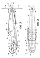
- la fig. 1 est une vue latérale schématique qui montre un appareil ULM composé d'un deltaplane et d'un fuselage motorisé selon l'invention, cet appareil étant en vol avec son pilote en position couchée,
- la fig. 2 montre la même appareil à l'arrêt juste avant le décollage, le pilote étant en position debout,
- la fig. 3 est une vue en coupe longitudinale verticale du fuselage,
- la fig. 4 est une vue en plan du fuselage, et
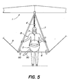
- les fig. 5 et 6 sont des vues frontales montrant comment le même fuselage peut être suspendu respectivement à un deltaplane ou à un parapente, au moyen d'organes de suspension appropriés.
- fig. 1 is a schematic side view which shows an ULM device composed of a hang glider and a motorized fuselage according to the invention, this device being in flight with its pilot in the lying position,
- fig. 2 shows the same aircraft stopped just before takeoff, the pilot being in the standing position,
- fig. 3 is a view in vertical longitudinal section of the fuselage,
- fig. 4 is a plan view of the fuselage, and
- fig. 5 and 6 are front views showing how the same fuselage can be hung respectively from a hang glider or a paraglider, by means of suitable suspension devices.
L'exemple d'appareil illustré par les fig. 1, 2 et 5 se compose d'un deltaplane classique 1 (appelé aussi aile de vol libre) et d'un fuselage motorisé 2 selon l'invention, le fuselage étant suspendu au deltaplane au moyen de deux paires de suspentes souples 3 dont les extrémités inférieures sont accrochées à des têtes latérales 4 de support du fuselage, tandis que leurs extrémités supérieures sont rassemblées et accrochées ensemble par un mousqueton 4′ à une boucle de suspension classique 5 fixée à la structure 6 du deltaplane. Cette structure comporte également un organe de commande bien connu, appelé communément le trapèze, formé par deux barres obliques 7 dont les extrémités inférieures sont reliées entre elles par une barre transversale 8 et aux extrémités du deltaplane par des câbles 9 et 10.The example of apparatus illustrated in figs. 1, 2 and 5 consists of a classic hang-glider 1 (also called free flight wing) and a
On notera que les deux suspentes latérales postérieures 3 peuvent être remplacées par une seule suspente arrière située dans le plan médian. Celle-ci peut être équipée d'un coupe-circuit électrique qui arrête le moteur quand la suspente se détend, afin d'éviter que l'hélice déployée touche le deltaplane 1 si l'arrière du fuselage s'en rapproche, notamment dans des conditions de vol perturbées. Cette suspente arrière pourrait aussi être remplacée par un bras rigide.Note that the two rear
Le fuselage 2, dont la construction est visible plus particulièrement dans les fig. 3 et 4, comporte une coque légère et rigide 12 de forme aérodynamique, réalisée par exemple en polyester armé de fibres de verre. Cette coque présente une forme fuselée dans laquelle un pilote 13 peut prendre place en position couchée ventrale sans que son corps émerge sensiblement à l'extérieur de la coque. Ainsi, cet ensemble présente de bonnes caractéristiques de pénétration dans l'air qui, pour le vol plané, sont aussi favorables que celles d'un pilote de deltaplane classique, enfermé dans un cocon souple. Pour laisser passer le corps du pilote, la coque 12 est pourvue d'une ouverture supérieure 14 et d'une ouverture inférieure 15 qui sont partiellement superposées au moins dans la zone du centre de gravité G du fuselage, pour permettre au pilote 13 de se tenir debout dans cette zone, comme le montre la fig. 2. En avant de cette zone, il est prévu une couchette basculante 16 (supprimée sur la fig. 4 pour la clarté du dessin) qui est montée de manière pivotante et amovible, par exemple sur une barre transversale 17 solidaire de la coque au niveau des hanches du pilote. De plus, cette couchette est pourvue de sangles 18 (fig. 2) permettant de suspendre le fuselage aux épaules du pilote quand celui-ci est debout. Ainsi, le pilote peut s'attacher la couchette 16 sur le torse, avant de se placer dans le fuselage et d'accrocher celui-ci à la couchette. En dessous de la couchette 16, la coque 12 comporte une structure transversale 20 qui forme notamment un alvéole 21 pour un parachute de secours et un alvéole 22 pour des instruments 23 exposés aux yeux du pilote, derrière un pare-brise profilé 24 en matière synthétique transparente. Selon les cas, ces alvéoles pourraient être prévus latéralement ou supprimés pour réduire la hauteur de la coque.The
Un moteur 26, par exemple à essence, est disposé dans la partie avant du fuselage, en dessous de la tête du pilote 13 quand celui-ci est en position couchée, entre la structure 20 et une paroi inférieure 27 de la coque 12. Une ou plusieurs ouvertures 28 dans l'avant de la coque 12 permettent l'entrée d'air pour le refroidissement du moteur, cet air étant dévié sous le pilote dans la structure 20 et s'échappant par l'ouverture inférieure 15. Un tuyau d'échappement des gaz 29 s'étend à l'extérieur de la coque jusqu'à un pot d'échappement 29′.A
Une hélice 30 à pales rabattables 31 est portée par un arbre rotatif 32 monte dans une position stationnaire à l'arrière du fuselage 2, de manière que la direction de l'axe de rotation 33 de l'hélice corresponde à la direction de poussée voulue. L'arbre 32 est monté par un palier 34 dans une paroi arrière 35 de la coque 12. Le moteur 26 est relié à l'arbre 32 par une boîte de réduction 36, entraînant un arbre de transmission tubulaire 37 pourvu d'un joint d'articulation 38 à l'arrière et protégé par un tube fixe 39 qui s'étend entre les jambes du pilote. Dans le présent exemple,le joint 38 est prévu pour permettre une inclinaison de l'arbre 37 par rapport à l'axe 33 de l'hélice, mais il n'est pas nécessaire dans tous les cas. En effet, l'axe 33 de l'hélice peut être dans le prolongement de l'arbre de transmission si celui-ci n'est pas trop incliné. L'hélice 30 a deux pales 31 montées chacune par une articulation 40 sur un moyeu 41 solidaire de l'arbre 32, cette articulation contenant un ressort qui tend à rabattre la pale parallèlement à l'axe 33 quand l'hélice ne tourne pas, dans la position dessinée en traits continus en fig. 1. Cette position repliée de l'hélice 30, située avantageusement dans le prolongement de la coque 12, est extrêmement favorable pour la finesse en vol plané. En outre, elle évite un accrochage des pales à des obstacles ou au sol, par exemple à l'atterrissage. L'hélice peut aussi comporter plus de deux pales.A
Dès que l'hélice est entraînée en rotation par le moteur, les pales 31 tendent à s'écarter sous l'effet de la force centrifuge et de la réaction de l'air, pour prendre leur position de propulsion illustrée par les fig. 2 et 3. Pour éviter que l'hélice entre alors en contact avec le sol, spécialement au décollage, une béquille rabattable 42 est articulée en 43 sous la partie arrière de la coque, cette béquille étant rabattue au moyen d'un élément élastique 44 et déployée par le pilote au moyen d'un câble de tirage 45. Une ouverture arrière 46 est ménagée pour recevoir son extrémité dans l'arrière de la coque. Bien entendu, on peut prévoir un organe de protection différent à la place de cette béquille, par exemple un arceau ou une double béquille en V renversé assurant un appui stable sur le sol et une protection sur les côtés. Une autre construction avantageuse, non représentée, consiste à remplacer la béquille basculante 42 par une béquille qui s'escamote dans la coque par coulissement à travers une ouverture de petite taille. L'extrémité avant de cette béquille coulissante peut être articulée à un manchon qui coulisse sur le tube 39. En position déployée, son extrémité arrière peut venir assez près de la circonférence de l'hélice et assurer ainsi une protection efficace.As soon as the propeller is driven in rotation by the motor, the
Les dessins montrent également une implantation avantageuse d'un réservoir d'essence 48 monté dans une zone centrale de la coque 2, au-dessus des cuisses du pilote, et raccordé au moteur par une canalisation latérale 49. Ce réservoir peut avoir une capacité de quelques litres, suffisante pour une ou plusieurs heures de vol motorisé.The drawings also show an advantageous layout of a
L'ensemble du fuselage 2 peut être construit de façon à présenter un poids total relativement modeste, de l'ordre de 20 à 30 kg, pour être supporté par les épaules du pilote se trouvant en position debout. La position du centre de gravité G à proximité immédiate du centre de gravité du pilote est permise par la répartition favorable des éléments mécaniques, avec l'hélice 30 à l'arrière et le moteur 26 à l'avant. Dans certains cas, on peut obtenir une répartition différente en rejettant à l'arrière la boîte de réduction 36.The
L'appareil ULM est prévu pour voler tantôt au moteur, tantôt en vol plané. Le décollage s'effectue généralement (mais pas nécessairement) au moteur, dans la position illustrée par la figure 2. Le pilote lance le moteur, soulève le deltaplane 1 et le fuselage 2 et se met à courir avec l'aide de la poussée fournie par l'hélice, jusqu'à ce que la portance de la voilure soulève successivement le fuselage, puis le pilote s'appuyant sur la couchette basculante 16. Le pilote rentre alors ses jambes dans la coque pour se mettre en position couchée, tout en gardant ses bras à l'extérieur pour piloter l'appareil en tenant dans ses mains la barre de trapèze 8. Il rabat la béquille 42 en relâchant le câble 45. Les commandes du moteur peuvent être disposées à sa portée sur un côté de la coque, ce qui lui permet par exemple d'arrêter le moteur après avoir atteint une altitude suffisante, de faire un vol plané d'une certaine durée, puis de remettre en marche le moteur pour voler plus longtemps. L'atterrissage peut se faire de la même manière qu'avec un deltaplane classique, avec le moteur arrêté, l'hélice repliée et le pilote en position debout. La barre de trapèze 8 peut être équipée d'une paire de roulettes 50 à titre de protection, pour éviter de toucher le sol. Cela permet aussi d'atterrir en glissade, le pilote restant alors en position couchée.The ULM device is designed to fly sometimes with the engine, sometimes in gliding flight. Takeoff is generally (but not necessarily) with the engine, in the position illustrated in Figure 2. The pilot starts the engine, lifts the hang glider 1 and the
Un avantage important du fuselage 2 décrit ci-dessus réside dans le fait qu'il peut être utilisé aussi bien avec le deltaplane 1 qu'avec un parapente 51 (parachute directionnel), comme le montre la figure 6. Pour cela, il suffit de grouper différemment les extrémités supérieures des suspentes 3 du fuselage, en raccordant les deux suspentes 3a de gauche à une première boucle 52a et les deux suspentes de droite 3b à une seconde boucle 52b, ces deux boucles étant espacées latéralement l'une de l'autre au-dessus des épaules du pilote 13. De telles boucles existent déjà sur les parapentes, pour permettre la suspension d'un harnais portant le pilote à l'extrémité inférieure des suspentes 53 raccordées respectivement à la moitié de gauche et à celle de droite de la coupole textile 54 du parapente. Afin de stabiliser latéralement le fuselage dans des virages serrés, on peut ajouter une paire de diagonales, éventuellement élastiques, reliant chaque boucle 52a, 52b à l'extrémité inférieure de la suspente arrière 3 située du côté opposé. Pour permettre le pilotage en position couchée, les cordelettes classiques 55 de commande du parapente peuvent être prolongées pour passer sur des poulies montées à cet effet de chaque côté de la coque.An important advantage of the
Grâce à l'utilisation d'une hélice à pales rabattables, le décollage peut se faire sans danger de la manière suivante, la voilure du parapente étant posée sur le sol derrière le fuselage. En portant le fuselage 2, le pilote commence à avancer. La voilure du parapente se gonfle et monte au-dessus du pilote, qui peut alors lancer le moteur pour faire tourner l'hélice et décoller. Ainsi, les suspentes 53 du parapente ne risquent pas de s'accrocher à l'hélice et on peut se passer d'un grillage de protection autour de celle-ci.Thanks to the use of a propeller with folding blades, takeoff can be done safely as follows, the wing of the paraglider being placed on the ground behind the fuselage. By carrying the
Il faut remarquer qu'un fuselage de ce genre permet encore d'autres utilisations dans le domaine des sports et des divertissements, par exemple pour propulser un homme se tenant sur des skis ou sur un véhicule tel qu'un traîneau, un chariot à roulettes ou un bateau. Dans tous les cas, la proximité immédiate des centres de gravité du fuselage et du pilote est un avantage essentiel pour la facilité d'emploi de l'appareil.It should be noted that a fuselage of this kind allows still other uses in the field of sports and entertainment, for example to propel a man standing on skis or on a vehicle such as a sled, a trolley on wheels or a boat. In all cases, the immediate proximity of the centers of gravity of the fuselage and the pilot is an essential advantage for the ease of use of the aircraft.
Claims (10)
Applications Claiming Priority (2)
| Application Number | Priority Date | Filing Date | Title |
|---|---|---|---|
| FR8805842 | 1988-04-27 | ||
| FR8805842A FR2630704B1 (en) | 1988-04-27 | 1988-04-27 | MOTORIZED FUSELAGE AGENCY TO BE SUSPENDED FROM A WING |
Publications (1)
| Publication Number | Publication Date |
|---|---|
| EP0341208A1 true EP0341208A1 (en) | 1989-11-08 |
Family
ID=9365883
Family Applications (1)
| Application Number | Title | Priority Date | Filing Date |
|---|---|---|---|
| EP89810316A Withdrawn EP0341208A1 (en) | 1988-04-27 | 1989-04-27 | Powered fuselage suspended below a wing |
Country Status (2)
| Country | Link |
|---|---|
| EP (1) | EP0341208A1 (en) |
| FR (1) | FR2630704B1 (en) |
Cited By (6)
| Publication number | Priority date | Publication date | Assignee | Title |
|---|---|---|---|---|
| FR2668116A1 (en) * | 1990-10-23 | 1992-04-24 | Cros Michel | Improvement to ultralight or microlight aircraft in terms of the cockpit and the propulsion |
| CN101033005B (en) * | 2007-04-11 | 2010-07-21 | 谭大刚 | Suspension type gliding wing manpower flight driving device and ground surface simulated training rack for the same |
| GB2467137A (en) * | 2009-01-22 | 2010-07-28 | Rupert John Bickham Sweet-Escott | Folding propeller guard for an aircraft |
| DE102013000461A1 (en) * | 2013-01-14 | 2014-07-31 | Michael Heger | Drive device for paragliders, has motors arranged in front of paraglider pilots in flight direction, where paragliders pilots and harnesses are connected to existing widespread connectivity retainers |
| RU2547122C2 (en) * | 2014-02-19 | 2015-04-10 | Николай Валерьевич Чистяков | Emergency recovery device of remotely piloted aircraft |
| WO2023159304A1 (en) * | 2022-02-25 | 2023-08-31 | Bard Maurice Rheal | Personal flying apparatus incorporating a harness and method of facilitating human flight |
Families Citing this family (1)
| Publication number | Priority date | Publication date | Assignee | Title |
|---|---|---|---|---|
| CH700620A2 (en) * | 2009-03-30 | 2010-09-30 | Andre Lecoultre | Power unit ultralight. |
Citations (4)
| Publication number | Priority date | Publication date | Assignee | Title |
|---|---|---|---|---|
| FR2543512A1 (en) * | 1983-03-30 | 1984-10-05 | Rousseau Yves | Propulsion device especially for aircraft of the microlight type, as well as the aircraft equipped with this device |
| GB2141985A (en) * | 1983-06-23 | 1985-01-09 | Sweet Escott Rupert John Bickh | A propulsion unit for an aircraft |
| DE3440823A1 (en) * | 1984-11-08 | 1986-05-15 | Hajo 5100 Aachen Harms | Ultralight aircraft pod for hang gliders |
| WO1986007329A1 (en) * | 1985-06-13 | 1986-12-18 | Lecoultre Andre | Motorized ultra-light flying craft with retractable propeller |
-
1988
- 1988-04-27 FR FR8805842A patent/FR2630704B1/en not_active Expired - Fee Related
-
1989
- 1989-04-27 EP EP89810316A patent/EP0341208A1/en not_active Withdrawn
Patent Citations (4)
| Publication number | Priority date | Publication date | Assignee | Title |
|---|---|---|---|---|
| FR2543512A1 (en) * | 1983-03-30 | 1984-10-05 | Rousseau Yves | Propulsion device especially for aircraft of the microlight type, as well as the aircraft equipped with this device |
| GB2141985A (en) * | 1983-06-23 | 1985-01-09 | Sweet Escott Rupert John Bickh | A propulsion unit for an aircraft |
| DE3440823A1 (en) * | 1984-11-08 | 1986-05-15 | Hajo 5100 Aachen Harms | Ultralight aircraft pod for hang gliders |
| WO1986007329A1 (en) * | 1985-06-13 | 1986-12-18 | Lecoultre Andre | Motorized ultra-light flying craft with retractable propeller |
Cited By (7)
| Publication number | Priority date | Publication date | Assignee | Title |
|---|---|---|---|---|
| FR2668116A1 (en) * | 1990-10-23 | 1992-04-24 | Cros Michel | Improvement to ultralight or microlight aircraft in terms of the cockpit and the propulsion |
| CN101033005B (en) * | 2007-04-11 | 2010-07-21 | 谭大刚 | Suspension type gliding wing manpower flight driving device and ground surface simulated training rack for the same |
| GB2467137A (en) * | 2009-01-22 | 2010-07-28 | Rupert John Bickham Sweet-Escott | Folding propeller guard for an aircraft |
| DE102013000461A1 (en) * | 2013-01-14 | 2014-07-31 | Michael Heger | Drive device for paragliders, has motors arranged in front of paraglider pilots in flight direction, where paragliders pilots and harnesses are connected to existing widespread connectivity retainers |
| DE102013000461B4 (en) * | 2013-01-14 | 2020-07-02 | Michael Heger | Universal drive device for paragliders |
| RU2547122C2 (en) * | 2014-02-19 | 2015-04-10 | Николай Валерьевич Чистяков | Emergency recovery device of remotely piloted aircraft |
| WO2023159304A1 (en) * | 2022-02-25 | 2023-08-31 | Bard Maurice Rheal | Personal flying apparatus incorporating a harness and method of facilitating human flight |
Also Published As
| Publication number | Publication date |
|---|---|
| FR2630704B1 (en) | 1993-07-09 |
| FR2630704A1 (en) | 1989-11-03 |
Similar Documents
| Publication | Publication Date | Title |
|---|---|---|
| US4071206A (en) | Portable helicopter | |
| CA3020209C (en) | Device for propelling a passenger | |
| EP0392911A1 (en) | Device permitting the transformation of a motorcycle into an ultra-light aircraft | |
| WO2006077315A1 (en) | Air locomotion method and multi-purpose aircraft having inflatable wing(s) using two different inflating systems | |
| FR2667568A1 (en) | Individual powered flight apparatus | |
| EP0341208A1 (en) | Powered fuselage suspended below a wing | |
| CN201052838Y (en) | Manpower aircraft | |
| FR2498554A1 (en) | Wind powered craft with stayed mast - has supple axially symmetrical sail fixed to mast top by slidable universal joint | |
| EP2488409B1 (en) | Dirigible airship | |
| EP0327778B1 (en) | Seat harness for a gliding airfoil chute | |
| FR2685284A1 (en) | AIR SPORTS LEISURE DEVICE. | |
| WO2003043885A1 (en) | Remote-controlled flying craft, in particular for aerial photography | |
| EP0225346A1 (en) | Motorized ultra-light flying craft with retractable propeller | |
| WO2010111800A1 (en) | Ultralight motor-driven aircraft | |
| WO1986004836A1 (en) | Convertible airplane | |
| EP0217686A1 (en) | Aircraft of the parawing type | |
| EP0575344B1 (en) | Microli flying device | |
| FR2543512A1 (en) | Propulsion device especially for aircraft of the microlight type, as well as the aircraft equipped with this device | |
| FR2583375A1 (en) | Motorised ultralight flying machine with foldable propeller | |
| US20230356839A1 (en) | Special electric propulsion system to power paragliders and other small, light aircraft | |
| RU2124458C1 (en) | Rotoplane and method of control of its flight | |
| FR2744094A1 (en) | Wind propelled glider | |
| FR2589426A2 (en) | Motorised ultralight flying machine with retractable propellor | |
| FR3133370A1 (en) | secure bucket-chassis of paramotor with birotor propulsion exported rear lateral | |
| WO1988000152A1 (en) | Foldable wing, particularly for slope flight |
Legal Events
| Date | Code | Title | Description |
|---|---|---|---|
| PUAI | Public reference made under article 153(3) epc to a published international application that has entered the european phase |
Free format text: ORIGINAL CODE: 0009012 |
|
| AK | Designated contracting states |
Kind code of ref document: A1 Designated state(s): AT BE CH DE ES FR GB GR IT LI LU NL SE |
|
| 17P | Request for examination filed |
Effective date: 19900423 |
|
| 17Q | First examination report despatched |
Effective date: 19910712 |
|
| STAA | Information on the status of an ep patent application or granted ep patent |
Free format text: STATUS: THE APPLICATION IS DEEMED TO BE WITHDRAWN |
|
| 18D | Application deemed to be withdrawn |
Effective date: 19911130 |