EP0341155A1 - Spannvorrichtung, um Platten oder Profilstähle gegeneinander zu spannen - Google Patents
Spannvorrichtung, um Platten oder Profilstähle gegeneinander zu spannen Download PDFInfo
- Publication number
- EP0341155A1 EP0341155A1 EP89401253A EP89401253A EP0341155A1 EP 0341155 A1 EP0341155 A1 EP 0341155A1 EP 89401253 A EP89401253 A EP 89401253A EP 89401253 A EP89401253 A EP 89401253A EP 0341155 A1 EP0341155 A1 EP 0341155A1
- Authority
- EP
- European Patent Office
- Prior art keywords
- clamping
- carriage
- axis
- roller
- central axis
- Prior art date
- Legal status (The legal status is an assumption and is not a legal conclusion. Google has not performed a legal analysis and makes no representation as to the accuracy of the status listed.)
- Withdrawn
Links
- 229910000831 Steel Inorganic materials 0.000 title description 2
- 239000010959 steel Substances 0.000 title description 2
- 238000006073 displacement reaction Methods 0.000 claims description 11
- 239000002184 metal Substances 0.000 description 4
- 230000000903 blocking effect Effects 0.000 description 2
- 230000001154 acute effect Effects 0.000 description 1
- 238000013459 approach Methods 0.000 description 1
- 230000000694 effects Effects 0.000 description 1
- 239000000463 material Substances 0.000 description 1
- 238000007493 shaping process Methods 0.000 description 1
Images


Classifications
-
- B—PERFORMING OPERATIONS; TRANSPORTING
- B25—HAND TOOLS; PORTABLE POWER-DRIVEN TOOLS; MANIPULATORS
- B25B—TOOLS OR BENCH DEVICES NOT OTHERWISE PROVIDED FOR, FOR FASTENING, CONNECTING, DISENGAGING OR HOLDING
- B25B5/00—Clamps
- B25B5/16—Details, e.g. jaws, jaw attachments
- B25B5/166—Slideways; Guiding and/or blocking means for jaws thereon
-
- B—PERFORMING OPERATIONS; TRANSPORTING
- B25—HAND TOOLS; PORTABLE POWER-DRIVEN TOOLS; MANIPULATORS
- B25B—TOOLS OR BENCH DEVICES NOT OTHERWISE PROVIDED FOR, FOR FASTENING, CONNECTING, DISENGAGING OR HOLDING
- B25B5/00—Clamps
- B25B5/06—Arrangements for positively actuating jaws
- B25B5/12—Arrangements for positively actuating jaws using toggle links
- B25B5/122—Arrangements for positively actuating jaws using toggle links with fluid drive
Definitions
- the present invention relates to devices for clamping at least one set of two plates or sections one against the other, of the type comprising at least one clamping head, said clamping head comprising a body, a clean clamping piece. to pivot about a fixed axis integral with the body and having a clamping end intended to clamp said plates together on a counterpart, and means for rotating said clamping piece around the fixed axis, comprising at least one link, one of the ends of which is fixed to the said clamping piece pivotally about an axis integral with the said clamping piece and parallel to the fixed axis, and the other end of which is fixed to a carriage so the pivoting around the axis of at least one roller of said movable carriage substantially linearly along at least one guide ramp of determined shape, between a so-called erasing position of the clamping piece and a so-called clamping position, said ramp being attached to the body on the side of the fixed axis opposite the side occupied by the clamping end, when the carriage is in said clamping position.
- the present invention aims to provide a clamping device of the type defined above responding better than those previously known to the requirements of practice, in particular in that it allows the locking of plates or profiles against each other without any risk of blocking because, structurally, no bracing between clamping piece, link and displacement carriage is possible; it allows, in a preferred embodiment, to maintain substantially constant throughout the lifetime of the clamping heads (1,600,000 cycles), the force applied by the clamping piece, via its clamping end, on the plates clamped against each other; it also makes it possible to modulate the force exerted during the clamping, according to the specific use needs of the clamping heads; Finally, in an advantageous embodiment, it allows the control of several clamping heads by means of the same small, compact monobloc assembly, with two different tightening sequences possible for each clamping head.
- the invention proposes in particular a device for clamping at least one set of two plates or profiles, one against the other, of the type defined above, characterized in that the guide ramp has a surface curve, concave, in contact with the roller when the carriage comes into the clamping position, the centers of curvature of which at each point on said surface are located on the side of the fixed axis with respect to the plane defined by the central axis of the axis of the rod, integral with the clamping piece, and the central axis of the roller of the carriage when the latter is in said clamping position, and the distance between the central axis of the axis of the rod, integral with the clamping piece, and the central axis of the roller, is greater than the distance between the central axis of the fixed axis and a plane parallel to the fixed axis passing through the central axis of the roller, when the carriage is in said clamping position.
- the guide ramp comprises, at and near the curved surface in contact with the roller, a hollowed-out central portion, provided with a spring arranged to exert a determined force on the link when said carriage is in the clamping position, via the roller, and transversely to
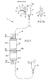
- Figure 1 shows a device 1 for clamping at least one set 2 of two metal plates or sections 3 and 4, comprising several clamping heads 5, 5b actuated by cables 6, 6b push-pullers which allow to transmit as well the traction forces than the thrust forces. These cables 6, 6b are guided by sheaths 7, 7b and are actuated by pneumatic linear displacement means 8, supplied with compressed air at 9a, 9b and 10a, 10b.
- Each of the clamping heads is similar to the clamping head 5 which will now be described.
- the clamping head 5 comprises a body 11 and a clamping part 12 having a clamping end 13 intended to clamp the plates 3, 4 together on a counterpart 14 itself rigidly fixed to a support 15 integral with the clamping head 5
- the clamping piece 12 is arranged to reach two extreme positions, a position 16 for releasing the plates 3 and 4 and a position 17 for clamping the plates 3 and 4 against the counterpart 14.
- Figure 1a is a front view of the clamping head 5 showing the body 11 consisting of two halves 18 and 19, separable, and fixed to each other by means known per se. This constitution allows access to the interior of the clamping head.
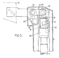
- FIG 2 shows the interior of the clamping head 5 of Figure 1.
- the clamping piece 12 comprises for example a connecting rod 20, rigidly fixed at 21 to the rest of said guide piece.
- the connecting rod 20 is able to pivot around the fixed axis 22, integral with the body 11.
- Means 23 for rotating the clamping piece 12 around the fixed axis 22 are provided. These means 23 comprise at least one connecting rod 24, one of the ends 25 of which is fixed to the connecting rod 20 so as to pivot about an axis 26, integral with said connecting rod 20, the axis 26 being parallel to the fixed axis 22, and the other end 27, of said rod 24, is fixed to a carriage 28, so as to pivot around the axis 29 of a roller 30 of said carriage 28.
- Said carriage 28 is movable, via its roller 30, substantially linearly along a ramp 31 for guiding between a position 32 of the carriage known as the erasure of the clamping piece (see FIG. 2), corresponding to the position 16 of the clamping piece for releasing the pieces 3 and 4, and a position 33 of the carriage known as for clamping the clamping piece (see FIG. 5) corresponding to position 17 of the clamping piece, for clamping the pieces 3 and 4 against the counterpart 14.
- the ramp 31 is fixed to the body 11 of the clamping head on one side of the fixed axis 22, opposite the side occupied by the clamping end 13, when the carriage 28 is in a position clamp 33 (see Figure 5).
- Figures 2, 3 and 4 appear locking means 34 of the carriage 28 in position 32 of the carriage, in the position of erasure of the clamping piece.
- These locking means 34 comprise two rods 35 and 36, substantially parallel, and located on either side of the carriage 28, for example parallel to the fixed axis 22.
- the rods 35 and 36 are fixed to the body 11 and are clean to compress a ball 37, integral with the carriage 28 by means of known type, in a notch 38 of an end portion 39 of the puller-pusher cable 6 of the linear displacement means.
- the end portion 39 is fixed to the carriage by a pin 40 cooperating with two oblong holes 41 made laterally in the carriage 28 with a functional clearance.
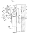
- FIG. 5 shows the clamping head in the clamping position, the carriage 28 having been pushed back to the clamping position 33 of the clamping piece.
- the guide ramp 31 has a curved, concave surface 44 of contact with the roller 30 when the latter comes into the position 33 for clamping the clamping piece such as the centers of curvature, in each of the points of said surface, are located on the side of the fixed axis 22, with respect to the plane 45 formed by the central axis 26 ′ of the axis of the rod 24 secured to the rod 20 of the clamping piece 12, and the central axis 29 ′ of the axis 29 of the roller 30 of the carriage 28, when said carriage is in the position 33 for clamping the clamping piece (see FIG.
- the radii of curvature of the surface 44 are such that the centers of curvature are located below the plane 45 in the direction of the fixed axis 22, with respect to to this plane.
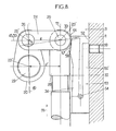
- the distance d between the central axis 26 ′ of the axis 26 of the rod 24 and the central axis 29 ′ of the axis 29 of the roller 30, is provided greater than the distance d ′ between the central axis 22 ′ of the fixed axis 22 and a plane 51 parallel to the fixed axis 22, passing through the axis central 29 ′ of the axis of the roller 29 when the carriage 28 is in the clamping position 33 (see FIG. 8).
- the angle ⁇ between the plane 50 passing through the central axis 26 ′ of the axis 26 of the link 24 secured to the clamping piece, and the central axis 29 ′ of the roller, and the plane 49, defined by said axis 26 ′ of the connecting rod and central axis 22 ′ of the fixed axis 22, is thus maintained at a value always less than 90 °, which makes it possible to avoid any risk of bracing and therefore of blocking.
- the device is such that, throughout the duration of travel by the roller of the curved surface corresponding to a stroke of the carriage, for example of a few millimeters, the position of the connecting rod 20 remains substantially identical, despite the movement of the rod 24, which results in a substantially constant clamping force.
- the radii of curvature 46, 47, 48 etc. of the curved surface 44 and the distance d between the central axis 26 ′ of the axis 26, integral with the part 12 of the rod 24, and l 'central axis 29 ′ of the roller 29, are structurally arranged to maintain, during a determined stroke of the carriage, up to the clamping position 33, a substantially constant angle ⁇ between the plane 50 passing through the central axis 26 ′ of the axis 26 of the link integral with the clamping piece, and the central axis 29 ′ of the axis 29 of the roller 30, and the plane 49, passing through said central axis 26 ′ of the link, and the central axis 22 ′ Of the fixed axis 22.
- the centers of curvature of each point of the surface 44 are, for example, located in the same plane, advantageously the plane 49.
- the surface 44 can also be substantially cylindrical, in which case the curvature centers are substantially on the same straight line, parallel to the fixed axis 22.
- the clamping force on the plates being directly proportional to the angle ⁇ , a substantially constant clamping force is thus obtained for a stroke of a determined length, from the carriage.
- the angle ⁇ is between about 80 ° and 89 ° and preferably between 85 and 88 ° and the ratio between the distances defined above, d and d ′ , is between 1.02 and 1 , 1.
- the guide ramp 31 comprises, on an end part of which one of the portions is at the level of the curved surface of contact 44 with the roller, a hollowed-out central part 52, or housing, provided with a spring 53 constituted by a pin in steel.
- the pin 53 rests in said housing 52, with a freedom of movement relative to an axis 54 integral with the body 11 and is arranged to exert a determined force, on the rod 24, via the roller 30, transversely to the direction 55 of substantially linear movement of the carriage, when the latter comes into the clamping position.
- the pin is removable and has a flexible branch 56 provided with a convex surface portion 57, suitable for coming into contact with the roller 30.
- the flexible branch 56 is compressed by the roller 30, and the top 58 of said surface convex is exceeded by the roller 30, when the carriage 28 is in the clamping position 33, so that the roller is locked by the pin (see FIG. 8).
- Adjustment means constituted for example by a screw 59, arranged to act on the other branch 56 ′ of the pin, make it possible to increase, or decrease, the determined force exerted by the spring 53 on the rod 24 via the roller 30.
- the device 1 is actuated by the pneumatic linear displacement means 8 comprising a sequencer 60.
- This sequencer comprises two identical housings 61a and 61b (see FIG. 9) supplied with compressed air, either at 9a, 9b, or at 10a, 10b.
- each box 61a and 61b is respectively arranged a drawer 62a and 62b mobile, delimiting two chambers, respectively 63a, 64a and 63b, 64b, suitable for being filled with compressed air, and for pushing in one direction or the other, the drawers 62a, 62b.
- Each drawer comprises a shutter 65, between the two chambers 63a, 64a and 63b, 64b, so as to bypass, or not, said drawer during the operation of a housing.
- Each drawer 62a, 62b slides respectively inside the housings 61a, 61b in a leaktight manner seals 66a, 66b, of known type, being provided.
- the cables 6, 6a, 6b ... intended to actuate the clamping heads of the device are fixed through two free ends of the two boxes respectively, 67a and 67b, either to the drawer 62a of the box 61a or to the drawer 62b of the box 61b .
- This fixing is then carried out either via a control rod 68 directly fixed to the drawer of the box in which the cable enters, for example the cable 6 on the drawer 62a, or via a control rod 69 and an extension 70, passing through the drawer of the box in which the cable enters, and fixed on the drawer of the opposite box, for example the cable 6a on the drawer 62b.
- the cable 6 operates differently from the cable 6a.
- the supply of compressed air at 10a and 10b will have the effect of pushing the drawer 62b by pulling on the cable 6a and pushing the drawer 62a by pushing on the cable 6, and conversely, pulling on the cable 6 and push on the cable 6a, when the compressed air supply is at points 9a and 9b.
- Each of the clamping heads is connected to the pneumatic linear displacement means 8 so that the cables 6, 6a, 6b, etc. are actuated in the desired sequence.
- the means 8 are then supplied with compressed air by the inputs 9a and 9b or the inputs 10a and 10b so as to push or pull on the cables in the desired sequence, thereby making the clamps, or clearances, of the plates or sections 3 and 4, corresponding to each clamping head.
- This supply is done automatically, a simple remote-controlled valve (not shown), all or nothing, allowing, for example, the sending of compressed air at 9a and 9b or at 10a and 10b.
- Several clamping heads (for example 18 heads) can thus be controlled simultaneously, with two types of operating sequences and this, with simple, reliable means and unlikely to fail.
- the initial state is shown in FIG. 2.
- the clamping piece is raised and the carriage is in the release position 32.
- the sheets, or plates, or metal profiles, to be clamped one against the other are placed on the counterpart 14.
- the carriage 28 is in the locked position, the part 43, protruding or abutment coming to lock against the rod 36, the ball 37 being in its notch 38.
- the device then starts to move (see Figures 2, 3 and 4).
- the end 39 of the cable 6 moves inside the carriage 28, the axis 40 starting by compensating for the play in the oblong hole 41 existing in the carriage 28.
- the ball 37 is pushed back from the notch 39 and moves aside the rod 36 to bring it into a carriage release position, as shown in FIGS. 3 and 4.
- the carriage can then move linearly.
- the roller 30 rolls along the ramp 11 which initially comprises, for example, a linear part 70.
- FIG. 6 shows the roller 30 of the carriage before it approaches the concave curved part 44 of the ramp 31.
- the axis 49 of the connecting rod 20 and the axis 50 of the connecting rod 24 form an angle ⁇ which is acute .
- the spring 53 is not yet stressed.
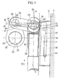
- Figure 7 there is shown several positions of the cooperating roller, on the one hand with the curved surface 44 of the ramp, and on the other hand with the spring 53 which it pushes the removable branch 56 between a position shown in phantom 71 , which is the initial position, and a maximum pushed back position 72.
- the axis 50 being included in the plane 45, the angle ⁇ between the axis 49 and the axis 50 remains substantially constant.
- the roller When the roller comes to cooperate with the curved part, it also biases the spring which is firstly pushed back until the roller exceeds the high point 58 of its convex part 57; then once the point 58 has been passed, the spring 53 exerts a thrust force additional to that of the link on the clamping piece to return to its initial position This additional thrust force can be adjusted via the means 59, as we have seen.
- the pneumatic means 8 pull on the cable 6.
- the carriage 28 and the spring 53 are then biased in the opposite direction, with a force reacting to the movement of the carriage on the roller increasing, until said roller has exceeded the hard point formed by the top 58 of the convex part of the spring.
- the spring therefore provides, much like a ratchet, mechanical locking, in addition to its thrust action during clamping.
- the carriage then moves to its release position 32 where the locking described above is carried out automatically, the end part 39 of the cable 6 being pulled, so that the fixing pin 40 on the carriage 28 slides in the oblong hole 41 of the carriage, and pushes, via the rods, the ball in the notch 38.
- the present invention is in no way limited to the embodiment more particularly envisaged; on the contrary, it embraces all variants, in particular those where: -
- the linear displacement means of the carriage are not actuated pneumatically but hydraulically or electrically; -
- the spring has a different shape from the pin shape more precisely described;
- the means of rotation of the clamping piece comprise two or more rods, one of the respective ends of which is fixed around the axis integral with the clamping piece, and the other of the respective ends of which is fixed to the carriage pivoting about the axis of two or more rollers arranged to cooperate with two or more guide rails of determined shape;
- the carriage has several guide rollers; -
- the locking means in the erasing position of the clamping piece, the carriage are of another type than that more specifically described.
Landscapes
- Engineering & Computer Science (AREA)
- Mechanical Engineering (AREA)
- Mounting, Exchange, And Manufacturing Of Dies (AREA)
- Jigs For Machine Tools (AREA)
- Manipulator (AREA)
Applications Claiming Priority (2)
| Application Number | Priority Date | Filing Date | Title |
|---|---|---|---|
| FR8806176A FR2630953B1 (fr) | 1988-05-06 | 1988-05-06 | Dispositif de bridage pour plaques ou profiles l'un contre l'autre |
| FR8806176 | 1988-05-06 |
Publications (1)
| Publication Number | Publication Date |
|---|---|
| EP0341155A1 true EP0341155A1 (de) | 1989-11-08 |
Family
ID=9366102
Family Applications (1)
| Application Number | Title | Priority Date | Filing Date |
|---|---|---|---|
| EP89401253A Withdrawn EP0341155A1 (de) | 1988-05-06 | 1989-05-03 | Spannvorrichtung, um Platten oder Profilstähle gegeneinander zu spannen |
Country Status (3)
| Country | Link |
|---|---|
| US (1) | US4921233A (de) |
| EP (1) | EP0341155A1 (de) |
| FR (1) | FR2630953B1 (de) |
Cited By (9)
| Publication number | Priority date | Publication date | Assignee | Title |
|---|---|---|---|---|
| EP0771614A3 (de) * | 1995-10-30 | 1997-07-23 | Btm Corp | Angetriebene Spann- und Messvorrichtung |
| FR2754484A1 (fr) * | 1996-10-15 | 1998-04-17 | Robotic | Perfectionnement pour dispositif de serrage du type comprenant un levier actionne par un piston |
| US5871250A (en) * | 1997-03-31 | 1999-02-16 | Btm Corporation | Sealed straight line gripper |
| US6115898A (en) * | 1995-06-06 | 2000-09-12 | Btm Corporation | Force multiplying apparatus for clamping a workpiece and forming a joint therein |
| FR2809650A1 (fr) * | 2000-05-31 | 2001-12-07 | Smc Kk | Dispositif de serrage |
| FR2817184A1 (fr) * | 2000-11-27 | 2002-05-31 | Smc Kk | Appareil de serrage |
| US6412845B1 (en) | 2000-07-07 | 2002-07-02 | Btm Corporation | Sealed gripper |
| ITTO20120106A1 (it) * | 2012-02-08 | 2013-08-09 | Vep Automation Srl | Apparecchiatura di bloccaggio di pezzi, particolarmente di fogli di lamiera |
| EP3130809A1 (de) | 2015-08-13 | 2017-02-15 | Pneumax S.p.A. | Gelenkhebelantrieb mit optimiertem wirkungsgrad |
Families Citing this family (13)
| Publication number | Priority date | Publication date | Assignee | Title |
|---|---|---|---|---|
| ES2084471T3 (es) * | 1992-11-05 | 1996-05-01 | Martin Breiter | Cabeza de embridado. |
| FR2702804B1 (fr) * | 1993-03-16 | 1995-05-19 | Genus Technologie Ind | Dispositif de serrage, notamment pour l'application de tôles ou profilés métalliques l'un contre l'autre. |
| DE19732600C2 (de) * | 1997-07-29 | 2000-03-30 | Benteler Werke Ag | Bauteilspanner |
| US6557841B2 (en) | 2001-06-26 | 2003-05-06 | Norgren Automotive, Inc. | Over-center power clamp toggle mechanism |
| ATE277721T1 (de) * | 2001-04-19 | 2004-10-15 | Univer Spa | Kniehebelspannvorrichtung |
| DE20218008U1 (de) | 2002-11-21 | 2003-03-06 | FESTO AG & Co., 73734 Esslingen | Anordnung von mehreren Handhabungsvorrichtungen |
| US6902160B1 (en) * | 2003-01-22 | 2005-06-07 | Zaytran, Inc. | Locating pin with integrated clamp |
| US6931980B1 (en) * | 2003-03-21 | 2005-08-23 | Zaytran, Inc. | Pneumatic device with cushioning mechanism |
| US8366085B2 (en) * | 2007-06-19 | 2013-02-05 | Phd, Inc. | Pin locating assembly |
| EP2177320A1 (de) * | 2008-10-15 | 2010-04-21 | UNIVER S.p.A. | Irreversible Kniehebelantriebsvorrichtung |
| DE202009002141U1 (de) | 2009-02-14 | 2009-04-23 | Tünkers Maschinenbau Gmbh | Vorrichtung mit einem über ein Stellglied und einer Kniehebelgelenkanordnung durch einen Antrieb in entgegengesetzten Richtungen antreibbaren Hebel, dem eine oder mehrere Massen zugeordnet ist bzw. sind, insbesondere zur Verwendung im Karosseriebau der Kfz-Industrie |
| JP6212309B2 (ja) * | 2013-07-05 | 2017-10-11 | 株式会社三興 | トグルクランプ |
| EP2921260B1 (de) * | 2014-03-20 | 2016-08-31 | UNIVER S.p.A. | Pneumatisch betreibbares Arbeitsgerät |
Citations (6)
| Publication number | Priority date | Publication date | Assignee | Title |
|---|---|---|---|---|
| FR2340798A1 (fr) * | 1976-02-13 | 1977-09-09 | Polymatic Sa | Tete de bridage irreversible a attelage flottant et demontage rapide |
| FR2484310A1 (fr) * | 1980-06-14 | 1981-12-18 | Sta Co Mettallerzeugnisse Gmbh | Dispositif de serrage a genouillere, notamment pour serrer des elements de carrosserie |
| US4396183A (en) * | 1982-05-10 | 1983-08-02 | Lymburner Robert K | Power actuated clamp |
| FR2540021A1 (fr) * | 1983-01-27 | 1984-08-03 | Franche Comte Alsace Etudes Te | Dispositif de serrage pneumatique a genouillere |
| FR2542656A3 (fr) * | 1983-03-16 | 1984-09-21 | Destaco Metallerzeug Gmbh | Dispositif de serrage a genouillere comportant un verin a double effet |
| EP0216710A1 (de) * | 1985-09-24 | 1987-04-01 | Fabrice Goussu | Mehrkopfspannvorrichtung mit einer einzelnen Fernbetätigung |
Family Cites Families (4)
| Publication number | Priority date | Publication date | Assignee | Title |
|---|---|---|---|---|
| US3702185A (en) * | 1970-12-11 | 1972-11-07 | Leland F Blatt | Cylinder operated power clamp |
| DE2813694C2 (de) * | 1978-03-30 | 1981-09-17 | Tünkers Maschinenbau GmbH, 4030 Ratingen | Druckmittelbetätigbare Kniehebelspannvorrichtung mit einem dopptelt wirkenden Spannzylinder, in dem ein Differentialkolben längsverschiebbar geführt ist |
| US4637597A (en) * | 1982-09-29 | 1987-01-20 | De-Sta-Co Division/Dover Corporation | Locking power clamp |
| FR2555926B1 (fr) * | 1983-12-02 | 1986-09-12 | Franche Comte Alsace Etudes Te | Dispositif de serrage pneumatique a genouillere |
-
1988
- 1988-05-06 FR FR8806176A patent/FR2630953B1/fr not_active Expired - Lifetime
-
1989
- 1989-05-03 EP EP89401253A patent/EP0341155A1/de not_active Withdrawn
- 1989-05-05 US US07/350,363 patent/US4921233A/en not_active Expired - Fee Related
Patent Citations (6)
| Publication number | Priority date | Publication date | Assignee | Title |
|---|---|---|---|---|
| FR2340798A1 (fr) * | 1976-02-13 | 1977-09-09 | Polymatic Sa | Tete de bridage irreversible a attelage flottant et demontage rapide |
| FR2484310A1 (fr) * | 1980-06-14 | 1981-12-18 | Sta Co Mettallerzeugnisse Gmbh | Dispositif de serrage a genouillere, notamment pour serrer des elements de carrosserie |
| US4396183A (en) * | 1982-05-10 | 1983-08-02 | Lymburner Robert K | Power actuated clamp |
| FR2540021A1 (fr) * | 1983-01-27 | 1984-08-03 | Franche Comte Alsace Etudes Te | Dispositif de serrage pneumatique a genouillere |
| FR2542656A3 (fr) * | 1983-03-16 | 1984-09-21 | Destaco Metallerzeug Gmbh | Dispositif de serrage a genouillere comportant un verin a double effet |
| EP0216710A1 (de) * | 1985-09-24 | 1987-04-01 | Fabrice Goussu | Mehrkopfspannvorrichtung mit einer einzelnen Fernbetätigung |
Cited By (13)
| Publication number | Priority date | Publication date | Assignee | Title |
|---|---|---|---|---|
| US6115898A (en) * | 1995-06-06 | 2000-09-12 | Btm Corporation | Force multiplying apparatus for clamping a workpiece and forming a joint therein |
| EP0771614A3 (de) * | 1995-10-30 | 1997-07-23 | Btm Corp | Angetriebene Spann- und Messvorrichtung |
| US5884903A (en) * | 1995-10-30 | 1999-03-23 | Btm Corporation | Powered clamp and gauging apparatus |
| FR2754484A1 (fr) * | 1996-10-15 | 1998-04-17 | Robotic | Perfectionnement pour dispositif de serrage du type comprenant un levier actionne par un piston |
| EP0836912A1 (de) * | 1996-10-15 | 1998-04-22 | Robotic | Spannvorrichtung mit einem durch einen Kolben angetriebenen Hebel |
| US5871250A (en) * | 1997-03-31 | 1999-02-16 | Btm Corporation | Sealed straight line gripper |
| FR2809650A1 (fr) * | 2000-05-31 | 2001-12-07 | Smc Kk | Dispositif de serrage |
| US6412845B1 (en) | 2000-07-07 | 2002-07-02 | Btm Corporation | Sealed gripper |
| FR2817184A1 (fr) * | 2000-11-27 | 2002-05-31 | Smc Kk | Appareil de serrage |
| ITTO20120106A1 (it) * | 2012-02-08 | 2013-08-09 | Vep Automation Srl | Apparecchiatura di bloccaggio di pezzi, particolarmente di fogli di lamiera |
| EP2626174A1 (de) * | 2012-02-08 | 2013-08-14 | VEP Automation S.r.l. | Klemmvorrichtung zum Klemmen von Werkstücken, insbesondere Blättern |
| EP3130809A1 (de) | 2015-08-13 | 2017-02-15 | Pneumax S.p.A. | Gelenkhebelantrieb mit optimiertem wirkungsgrad |
| EP3130809B1 (de) | 2015-08-13 | 2023-08-02 | Pneumax S.p.A. | Gelenkhebelantrieb mit optimiertem wirkungsgrad |
Also Published As
| Publication number | Publication date |
|---|---|
| FR2630953B1 (fr) | 1991-04-05 |
| FR2630953A1 (fr) | 1989-11-10 |
| US4921233A (en) | 1990-05-01 |
Similar Documents
| Publication | Publication Date | Title |
|---|---|---|
| EP0341155A1 (de) | Spannvorrichtung, um Platten oder Profilstähle gegeneinander zu spannen | |
| EP0593371B1 (de) | Antrieb für einen Dreistellungsschalter | |
| EP2674362B1 (de) | Bolzenschließvorrichtung | |
| FR2809650A1 (fr) | Dispositif de serrage | |
| FR2488667A1 (fr) | Dispositif de changement de vitesse pour bicyclette | |
| FR2675103A1 (fr) | Frein a main pour vehicule. | |
| EP2729332A2 (de) | Vorrichtung zur steuerung eines getriebes und einer feststellbremse eines kraftfahrzeuges mit einem gemeinsamen bedienhebel | |
| EP0597770B1 (de) | Modulare Frankiermaschine mit einer Vorrichtung zum Zusammenbauen und zur automatischen Verriegelung und Zentrierung von Modulen | |
| EP0216710B1 (de) | Mehrkopfspannvorrichtung mit einer einzelnen Fernbetätigung | |
| EP1026712A1 (de) | Anlage mit einem elektrischen Schalter und Verriegelung durch einen Kabel | |
| FR2568842A1 (fr) | Systeme de direction a colonne basculable | |
| FR2764254A1 (fr) | Dispositif de marchepied mobile pour un vehicule automobile | |
| EP0734338B1 (de) | Einrichtung zur befestigung eines rades eines motorrades am ständer und leistungsprüfstand dafür | |
| FR2462904A1 (fr) | Appui-tete pour fauteuil de traitement, notamment fauteuil dentaire | |
| EP0437413B1 (de) | Verschiebbare einheitliche Struktur zur Befestigung oder zum Unterstützen von Fahrzeugrädern | |
| FR2974250A1 (fr) | Dispositif de mise en contact electrique entre une plateforme et un engin, ensemble de lancement et procede associe | |
| FR2697566A1 (fr) | Serrure à pêne basculant. | |
| FR2945760A1 (fr) | Dispositif de fixation rapide par serrage d'un organe | |
| FR2781401A1 (fr) | Pince de prehension a verrouillage et deverrouillage automatiques | |
| EP1375046B1 (de) | Tragbare Punktschweisszange | |
| FR2524361A1 (fr) | Appareil de traction pour le halage d'un cable, d'une barre ou d'un organe comparable | |
| EP0057639A2 (de) | Trommelbremse | |
| EP0939015B1 (de) | Steuervorrichtung für Kraftfahrzeugfeststellbremse | |
| FR2966073A1 (fr) | Dispositif de fixation rapide a effort de serrage amplifie. | |
| EP0150150A2 (de) | Vorrichtung zum Einlegen optischer Stirnflächen von mindestens einem Paar optischer Fasern in eine Verbindungsvorrichtung |
Legal Events
| Date | Code | Title | Description |
|---|---|---|---|
| PUAI | Public reference made under article 153(3) epc to a published international application that has entered the european phase |
Free format text: ORIGINAL CODE: 0009012 |
|
| AK | Designated contracting states |
Kind code of ref document: A1 Designated state(s): AT BE CH DE ES GB GR IT LI LU NL SE |
|
| STAA | Information on the status of an ep patent application or granted ep patent |
Free format text: STATUS: THE APPLICATION IS DEEMED TO BE WITHDRAWN |
|
| 18D | Application deemed to be withdrawn |
Effective date: 19900509 |