EP0339890B1 - Châssis - Google Patents
Châssis Download PDFInfo
- Publication number
- EP0339890B1 EP0339890B1 EP89304016A EP89304016A EP0339890B1 EP 0339890 B1 EP0339890 B1 EP 0339890B1 EP 89304016 A EP89304016 A EP 89304016A EP 89304016 A EP89304016 A EP 89304016A EP 0339890 B1 EP0339890 B1 EP 0339890B1
- Authority
- EP
- European Patent Office
- Prior art keywords
- frame
- mounting
- seat
- child
- dove
- Prior art date
- Legal status (The legal status is an assumption and is not a legal conclusion. Google has not performed a legal analysis and makes no representation as to the accuracy of the status listed.)
- Expired - Lifetime
Links
Images


Classifications
-
- B—PERFORMING OPERATIONS; TRANSPORTING
- B62—LAND VEHICLES FOR TRAVELLING OTHERWISE THAN ON RAILS
- B62B—HAND-PROPELLED VEHICLES, e.g. HAND CARTS OR PERAMBULATORS; SLEDGES
- B62B7/00—Carriages for children; Perambulators, e.g. dolls' perambulators
- B62B7/04—Carriages for children; Perambulators, e.g. dolls' perambulators having more than one wheel axis; Steering devices therefor
- B62B7/14—Carriages for children; Perambulators, e.g. dolls' perambulators having more than one wheel axis; Steering devices therefor with detachable or rotatably-mounted body
- B62B7/145—Carriages for children; Perambulators, e.g. dolls' perambulators having more than one wheel axis; Steering devices therefor with detachable or rotatably-mounted body the body being a rigid seat, e.g. a shell
-
- B—PERFORMING OPERATIONS; TRANSPORTING
- B62—LAND VEHICLES FOR TRAVELLING OTHERWISE THAN ON RAILS
- B62B—HAND-PROPELLED VEHICLES, e.g. HAND CARTS OR PERAMBULATORS; SLEDGES
- B62B7/00—Carriages for children; Perambulators, e.g. dolls' perambulators
- B62B7/04—Carriages for children; Perambulators, e.g. dolls' perambulators having more than one wheel axis; Steering devices therefor
- B62B7/14—Carriages for children; Perambulators, e.g. dolls' perambulators having more than one wheel axis; Steering devices therefor with detachable or rotatably-mounted body
- B62B7/147—Carriages for children; Perambulators, e.g. dolls' perambulators having more than one wheel axis; Steering devices therefor with detachable or rotatably-mounted body rotatable as a whole to transform from seating to lying
-
- B—PERFORMING OPERATIONS; TRANSPORTING
- B62—LAND VEHICLES FOR TRAVELLING OTHERWISE THAN ON RAILS
- B62B—HAND-PROPELLED VEHICLES, e.g. HAND CARTS OR PERAMBULATORS; SLEDGES
- B62B9/00—Accessories or details specially adapted for children's carriages or perambulators
- B62B9/26—Securing devices for bags or toys ; Arrangements of racks, bins, trays or other devices for transporting articles
-
- B—PERFORMING OPERATIONS; TRANSPORTING
- B62—LAND VEHICLES FOR TRAVELLING OTHERWISE THAN ON RAILS
- B62B—HAND-PROPELLED VEHICLES, e.g. HAND CARTS OR PERAMBULATORS; SLEDGES
- B62B7/00—Carriages for children; Perambulators, e.g. dolls' perambulators
- B62B7/004—Carriages supporting a hammock-style seat
-
- B—PERFORMING OPERATIONS; TRANSPORTING
- B62—LAND VEHICLES FOR TRAVELLING OTHERWISE THAN ON RAILS
- B62B—HAND-PROPELLED VEHICLES, e.g. HAND CARTS OR PERAMBULATORS; SLEDGES
- B62B7/00—Carriages for children; Perambulators, e.g. dolls' perambulators
- B62B7/006—Carriages supporting a rigid seat
-
- Y—GENERAL TAGGING OF NEW TECHNOLOGICAL DEVELOPMENTS; GENERAL TAGGING OF CROSS-SECTIONAL TECHNOLOGIES SPANNING OVER SEVERAL SECTIONS OF THE IPC; TECHNICAL SUBJECTS COVERED BY FORMER USPC CROSS-REFERENCE ART COLLECTIONS [XRACs] AND DIGESTS
- Y10—TECHNICAL SUBJECTS COVERED BY FORMER USPC
- Y10T—TECHNICAL SUBJECTS COVERED BY FORMER US CLASSIFICATION
- Y10T403/00—Joints and connections
- Y10T403/32—Articulated members
- Y10T403/32254—Lockable at fixed position
- Y10T403/32426—Plural distinct positions
- Y10T403/32434—Unidirectional movement, e.g., ratchet, etc.
-
- Y—GENERAL TAGGING OF NEW TECHNOLOGICAL DEVELOPMENTS; GENERAL TAGGING OF CROSS-SECTIONAL TECHNOLOGIES SPANNING OVER SEVERAL SECTIONS OF THE IPC; TECHNICAL SUBJECTS COVERED BY FORMER USPC CROSS-REFERENCE ART COLLECTIONS [XRACs] AND DIGESTS
- Y10—TECHNICAL SUBJECTS COVERED BY FORMER USPC
- Y10T—TECHNICAL SUBJECTS COVERED BY FORMER US CLASSIFICATION
- Y10T403/00—Joints and connections
- Y10T403/57—Distinct end coupler
- Y10T403/5793—Distinct end coupler including member wedging or camming means
Definitions
- the invention relates to a frame, particularly a frame of a push-chair for a child, often known as a baby buggy.
- Such frames are usually foldable for storage and/or ease of transport. They often too fold in a "fore and aft" direction, that is by bringing the front and rear wheels closely together in the folded position, whereby a carrying tray or receptacle which in use is below the seat, can be retained in the buggy in both the erected and folded condition. It is sometimes desirable to have the seat in which the child sits, facing the pusher of the buggy and sometimes to face away from him (or her). It is also sometimes desirable to replace the seat with another kind, such as a cot if an infant is to be transported. For this it is desirable to have an angular positioning device, for example as shown in FR-A-2508989. Such a mechanism, however, has the disadvantage that it must cooperate with a frame member, so leading to accidental operation and hence the possibility of the seat being tilted without warning.
- a frame for removably supporting a member in a plurality of angular positions comprising a manually-operable mechanism which is adapted to support the member whereby that member is fixedly mountable in and releasable from the frame, the mechanism also providing adjustment of the member to a desired fixed angular position in relation to the frame by interengageable teeth means of the mechanism, the mechanism comprising a mounting lug which is rotatable to said desired fixed angular position and a manually operable cam device for releasing the teeth means for rotation to a desired said position, characterised by retractable pin means (14) for securing the member (3) in the frame (1).
- the frame may be a wheeled frame.
- the member may comprise a seat means such as a child's seat or cot or pram.
- the mounting lug may have a mounting device complementary to a mounting device of the seat means.
- the complementary mounting devices may comprise a substantially dove-tail shape projection on the lug and a substantially dove-tail shape blind slot on the seat means.
- the lug may be mounted under pressure of biassing means adapted to bias the teeth apart.
- the mechanism may comprise a lever which is movable between discrete positions whereby to allow locking of the seat means in the frame, angular adjustment thereof in the frame, and removal thereof from the frame.
- the mechanism may comprise a member rotatable to a plurality of discrete positions whereby to allow locking of the seat means in the frame, angular adjustment thereof in the frame, and the removal thereof from the frame.
- the rotatable member may be releasable for rotation by a press stud.
- a universal child support system comprising a frame as hereinbefore defined, a plurality of interchangeable seat means for mounting in and removal from the frame, and a support for a seat means when not in the frame.
- the support may be a bouncer frame.
- the seat means may include a child's car seat which is adapted for mounting in and removal from a car (or other vehicle) and for mounting in the frame and/or the bouncer frame as desired.
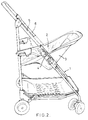
- a frame 1 for removably supporting child support means such as a seat means 3 for a child in a plurality of angular positions, comprising a manually operable lateral mechanism 4 which is adapted to support the seat means 3 whereby that seat means 3 is fixedly mountable in and releasable from the frame 1, the mechanism 4 also providing adjustment of the seat means 3 to a desired fixed angular position in relation to the frame 1.
- the frame 1 comprises two spaced side frame parts 5 and 6 of metal mounted on wheels, and being foldable fore and aft by the front or leading elongate members, comprising metal, usually metal tube being "breakable" at an elbow pivot, the fore and aft parts of each side frame part being connected by a "breakable” strut 7 to allow collapsing of the frame 1 when broken and when a secondary catch at the elbow pivot is also released.
- the fore tube member of each side frame part comprises two elongate members which in the erect position shown in Figs. 1 and 2 are more or less aligned, the lower (in use when erected) elongate member being secured in a housing 8 which provided part of the mechanism 4, Figs. 3-11.
- the housing 8 is a plastic moulding which comprises the mechanism 4 which has a manually operable lever 9 receivable in a recess 10 in the housing 8 on the outside of the frame (as considered in use).
- the housing 8 includes a bore 11 in which the slidable plastic plug 12 is reciprocable, being mounted on a rod 13 connected to the lever 9 and having two projecting pins 14 spaced apart on a diameter, the rod 13 passing therebetween.
- the mechanism 4 also includes a rotatable device or lug 15 secured to the rod 13 by a nut 16 in a recess 17 urged away from the housing 8 by biassing means in the form of a coil spring 18 mounted on the rod 13 and acting between an outer (in use) face of the device 15 and an inner face of the housing.
- the device 15 has two through bores 19 aligned with the pins 14 and carries on one face a mounting means in the form of a substantially dove-tail shaped projection 20 which is complementary in shape to a blind dove-tail shaped recess 21 in a mounting block 22 on a side frame 23 of the seat means 3.
- the opposite face or side of the device 15 to the projection 20 has a circumferential array of teeth 24 which face and are adapted to engage with a fixed circular array of teeth 25 on a part 26 of the housing 8 on the inside of the frame 1 in use.
- the lever 9 has a cam face 27, in this case a flat, for engaging the plug 12 at a face 29 and a push button 28 which operates a latch in the recess 10 so that the lever 9 can be pivoted therefrom.
- There is a further latch or stop 30 which engages the lever 9 in an intermediate position and which has to be released to release the lever 9 for pivoting to a position in which it projects at substantially 90° from the housing recess 10, for removal of the seat means 3.
- the frame 1 is used to support the seat means 3, the complementary dove-tail projection 20 at each side of frame 1 being received in the adjacent dove-tail blind slot 21 of the seat means 3 (it will be understood that there is an identical mechanism 4 at each side of the frame 1).
- the lever 9 is pivoted to a position in which it is latched by the first latch in the recess 10 (Fig. 3), so that the pins 14 project inwardly beyond the inner face of the projection 20 and engage in aligned holes 31 in the mounting block 22 of the seat means 3, the holes 31 being in a face of the dove-tail slot 21.
- the pins 14 thus lock or retain the seat means 3 in the frame 1.
- the seat means 3 is in the Fig. 1 position, facing foreward, that is away from the pusher, and the teeth 24, 25 are meshed.
- the seat means 3 is thus firmly retained in the frame 1 and in the desired angular position shown, Fig. 1. If it is desired to adjust the angular position to say the Fig.
- the push button 28 is again pushed to release the lever 9 which is pivoted to the first position which is at about 60° to the housing 8.
- the second latch 30 is then operated to release the lever 9 for further movement to 90° which action disengages the cam 27 from the plug 12 and effectively pushes the rod 13 inwardly so that the device 15 slides over the pins 14 and they no longer project from the device 15 and consequently are withdrawn from the holes 31 in the mounting block.
- the seat means 3 can then be removed from the frame 1 by lifting off dove-tail projection 20.
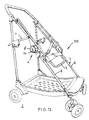
- FIGs. 12-15D there is shown in Figs. 13 and 14 a second embodiment of buggy 100 which has an alternative operating mechanism which replaces the lever mechanism 9 of the buggy shown in Figs. 1 and 2, which buggy in all other respects is the same as described for the first embodiment described with reference to Figs. 1 and 2.
- the frame 1 comprises two spaced side frame parts of metal mounted on wheels, and being foldable fore and aft by the front or leading elongate members, comprising metal, usually metal tube, being "breakable” at an elbow pivot, the fore and aft part of each side frame part being connected by a “breakable” strut to allow collapsing of the frame when broken and when a secondary catch at the elbow pivot is also released.
- the fore tube member of each side frame part comprises two elongate member which in the erect position shown in Figs. 13 and 14 are more or less aligned, the lower (in use when erected) elongate member being secured to a housing 8 which provides part of the manually operable mechanism 4 (Fig. 12).
- the mechanism 4 comprises a dove-tail spigot (not shown) on a side frame member of a removable seat, (also not shown) which is receivable in and demountable from a dove-tail shaped wedge and ratchet plate 15 of the mechanism.
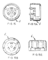
- the mechanism 4 also comprises a hand rotatable member or knob 9′ which sits in a part 8′ which has a notch or detent 8 ⁇ for receiving a member 33 internally of the know 9′ and which has a finger stud 34 which is depressible against spring 35 to run below the member 8′ which also has a fixed cam track 37.
- the knob 9′ also carries the plate 12 carrying the two spigots 14 for engaging in holes for retaining the seat and frame together.
- the housing 8 is a plastic moulding which includes a bore 11 in which the slidable plastic plug 12 is reciprocable, the plug carrying the two projecting pins 14 spaced apart on a diameter and being securable to the member 33 and hence the knob 9′ via a nut 12′ and a bold 15′ by which the ratchet plate 15 which is rotatable with the knob 9′, is secured thereto under pressure of biassing means in the form of a coil spring 18 mounted on the bolt 15′ and acting between an outer (in use) face of the device 15 and an inner (in use) face of the housing 8.
- the device 15 has a through bore 19 alignable with the pins 14 so that they can pass therethrough to engage in holes in mounting block of the seat to secure the seat in the frame in one position.
- There is a dove-tail shaped projection 20 which is complementary to a blind dove-tail shape recess in the mounting block on a side frame of the seat means, as in Figs. 1 and 2.
- the device 15 has a circumferential array of teeth which face and are adapted to engage with a fixed circular array of teeth or part 26 of the housing 8 on the inside of the frame (in use).
- the seat faces forwards that is in the direction of travel, the dove-tail spigot and slots being in engagement and ratchet teeth being intermeshed to lock the seat in the required angular positon.
- To adjust the "tilt" of the seat it is merely necessary to press the stud 34 to release the knobs 9′ so that it is rotatable manually so that it rides over cam track 37 to a lower part thereof so that it moves to the left as viewed to release the ratchet teeth 24, 26 under pressure of spring 18 so that the frame can be rotated to a new desired angular position, the knob 9′ then being returned manually to the original position to lock the seat in the new desired angular position when it rides up the cam track and draws the device 15 outwards against spring 18, when the stud 34 "pops into the slots".
- the stud 34 in the member 33 has to be depressed in the recess 8 ⁇ so as to be aligned therewith before the knob 9′ can be turned, the edge of the stud 34 engaging with an edge of the slot 8 ⁇ through which the stud protrudes in the normal, locking, position.
- the pressing and turning operation can be carried out with one thumb pressing action followed by a turning action.
- the seat is released from the frame by depression of the stud 34 as before and turning the member 9′ fully to a final angular position to withdraw the spigots 14 from the hole fully as in the first embodiment, so that the seat can be lifted from the wedge 15.
- the seat can be replaced by a pram-type child carrying device, and placed say in a baby-bouncer type support having a wedge or in a car having a support with a wedge.
- the seat means 3 or child support means such as a cot or car seat by be mounted in a vehicle or placed on a support such as a wire support which has mounting bloks with dove-tail shape projections.
- the wire support may be resilient, providing a baby bouncer.
- a cot or pram body with mounting blocks like the ones of the seat means may then be placed and secured in the frame.
- the invention therefore provides a universal baby or child support system which is flexible yet efficient.
Claims (13)
- Cadre pour supporter de manière amovible un élément dans plusieurs positions angulaires, comprenant un mécanisme à commande manuelle (4) qui est adapté pour supporter l'élément (3) de façon telle que l'élément (3) puisse être monté fixement sur le cadre (1) et en être détaché, le mécanisme (4) permettant également le réglage de l'élément (3) dans une position angulaire fixe désirée par rapport au cadre au moyen de dispositifs dentés à engagement mutuel (24, 25) du mécanisme, le mécanisme (4) comprenant un bloc entretoise de montage (15) pouvant pivoter dans ladite position angulaire fixe et un dispositif à came à commande manuelle (27), (37) pour libérer les dispositifs dentés (24, 25) afin de permettre la rotation dans une dite position désirée, caractérisé par un moyen à broche rétractable (14) pour fixer l'élément (3) dans le cadre (1).
- Cadre selon la revendication 1 caractérisé par l'élément (3) comprenant un moyen angulaire ajustable et/ou détachable (2) pour transporter un passager.
- Cadre selon la revendication 1 ou 2, caractérisé par un moyen à deux broches (14) passant à travers le bloc entretoise de montage (15) pour engager le moyen de siège (2).
- Cadre selon la revendication 3, caractérisé par le bloc entretoise de montage (15) ayant un dispositif de montage (20) complémentaire au dispositif de montage (21) du moyen de siège (2).
- Cadre selon la revendication 4, caractérisé par le dispositif de montage complémentaire (20, 21) comprenant une projection nettement en forme de queue d'aronde sur le bloc entretoise (15) et une rainure borgne nettement en forme de queue d'aronde sur le moyen de siège (2).
- Cadre selon l'une quelconque des revendications précédentes, caractérisé par le mécanisme (4) comprenant un levier (9) déplaçable entre des positions discrètes de manière à permettre le verrouillage du moyen de siège (3) dans le cadre (1), son ajustement angulaire dans le cadre (1), et son enlèvement du cadre (1).
- Cadre selon l'une quelconque des revendications 1 à 5, caractérisé par le mécanisme (4) comprenant un élément (9') pouvant pivoter dans plusieurs positions discrètes de manière à permettre le verrouillage du moyen de siège (3) dans le cadre (1), son ajustement angulaire dans le cadre (1), et son enlèvement du cadre (1).
- Cadre selon la revendication 7, caractérisé par l'élément pivotant (9') étant déverrouillable pour être entraîné en rotation par un bouton-poussoir (34).
- Cadre selon la revendication 8, caractérisé par l'élément pivotant (9') comprenant un bouton logé dans un boîtier (8') du mécanisme (4), et par le boîtier (8') comprenant le dispositif (37) sur lequel le bouton (9') ou une partie du bouton se déplace en rotation suivant l'enfoncement du bouton poussoir (34).
- Cadre selon la revendication 9, caractérisé par le bloc de pression (34) étant sur un élément (33) à l'intérieur du bouton et faisant normalement saillie à travers une encoche ou cran (8'') pour éviter la rotation.
- Système support pour enfant caractérisé en ce qu'il comprend un cadre (2, 3) selon l'une quelconque des revendications 1 à 10, plusieurs moyens de réception (3) interchangeables pour enfant pour montage et démontage dans le cadre, et un support pour les moyens de réception de l'enfant lorsque non monté dans le cadre.
- Système support pour enfant selon la revendication 11, caractérisé par le support comprenant un cadre flexible ayant un bloc de montage en forme de queue d'aronde (20) s'adaptant dans l'évidement en forme de queue d'aronde (21) dans le bloc de montage des moyens de réception d'enfant.
- Système support pour enfant selon la revendication 12, caractérisé par les moyens de réception d'enfant comprenant un siège d'enfant pour voiture qui est adapté pour montage et démontage dans une voiture (ou un autre véhicule) pour montage dans le cadre et/ou le cadre flexible au choix.
Priority Applications (1)
| Application Number | Priority Date | Filing Date | Title |
|---|---|---|---|
| AT89304016T ATE102883T1 (de) | 1988-04-25 | 1989-04-21 | Rahmen. |
Applications Claiming Priority (4)
| Application Number | Priority Date | Filing Date | Title |
|---|---|---|---|
| GB888809690A GB8809690D0 (en) | 1988-04-25 | 1988-04-25 | Frame |
| GB8809690 | 1988-04-25 | ||
| GB898903668A GB8903668D0 (en) | 1988-04-25 | 1989-02-17 | A frame |
| GB8903668 | 1989-02-17 |
Publications (3)
| Publication Number | Publication Date |
|---|---|
| EP0339890A2 EP0339890A2 (fr) | 1989-11-02 |
| EP0339890A3 EP0339890A3 (en) | 1990-08-22 |
| EP0339890B1 true EP0339890B1 (fr) | 1994-03-16 |
Family
ID=26293809
Family Applications (1)
| Application Number | Title | Priority Date | Filing Date |
|---|---|---|---|
| EP89304016A Expired - Lifetime EP0339890B1 (fr) | 1988-04-25 | 1989-04-21 | Châssis |
Country Status (6)
| Country | Link |
|---|---|
| US (1) | US5028061A (fr) |
| EP (1) | EP0339890B1 (fr) |
| JP (1) | JPH0214969A (fr) |
| AU (1) | AU636840B2 (fr) |
| DE (1) | DE68913791T2 (fr) |
| ES (1) | ES2050793T3 (fr) |
Cited By (1)
| Publication number | Priority date | Publication date | Assignee | Title |
|---|---|---|---|---|
| EP1398262A2 (fr) | 2002-09-10 | 2004-03-17 | "Zwei plus zwei" Marketing GmbH | Support pour enfant destiné à un cadre mobile |
Families Citing this family (76)
| Publication number | Priority date | Publication date | Assignee | Title |
|---|---|---|---|---|
| US5299818A (en) * | 1989-09-29 | 1994-04-05 | Bell Sports, Inc. | Child's bicycle seat and rack assembly |
| FR2666294A1 (fr) * | 1990-08-31 | 1992-03-06 | Baby Relax Snc | Perfectionnements aux poussettes pliantes pour enfants. |
| GB2248269B (en) * | 1990-09-18 | 1995-01-11 | Hestair Maclaren Ltd | Apparatus for supporting a member in a plurality of angular positions |
| US5062179A (en) * | 1991-03-11 | 1991-11-05 | Huang Ming Tai | Handle assembly for doll carriages |
| GB2254587B (en) * | 1991-04-08 | 1995-02-15 | Maclaren Ltd | Baby or infant transporting apparatus |
| US5364137A (en) * | 1993-04-05 | 1994-11-15 | Safe-Strap Company, Inc. | Infant highchair |
| DE9307172U1 (de) * | 1993-05-11 | 1993-09-16 | Hauck Gmbh & Co Kg | Zusammenklappbarer Kinderwagen |
| US5476306A (en) * | 1994-01-13 | 1995-12-19 | Westinghouse Electric Corporation | Chair back support adjustment mechanism |
| CN2202821Y (zh) * | 1994-09-13 | 1995-07-05 | 刘洋廷 | 一种可任调角度的肘接连接器 |
| US5687985A (en) * | 1994-11-04 | 1997-11-18 | Graco Children's Products, Inc. | Stroller, reclining and canopy tensioning mechanisms thereof |
| US5601297A (en) * | 1994-12-20 | 1997-02-11 | Stein; Linda P. | Universal infant carrier cart |
| US5833261A (en) * | 1995-08-17 | 1998-11-10 | Fisher-Price, Inc. | Footrest movable between two positions |
| DE29602814U1 (de) * | 1996-02-16 | 1996-06-05 | Hauck Gmbh & Co Kg | Kinderwagen, insbesondere Puppenwagen |
| US5718439A (en) * | 1996-05-31 | 1998-02-17 | Wang; Frank | Stroller with detachable seat member |
| FR2753158B1 (fr) * | 1996-09-10 | 1998-10-30 | Ampafrance | Dispositif d'accrochage d'une nacelle sur une poussette pour enfant, poussette et support equipes d'un tel dispositif |
| FR2753159B1 (fr) | 1996-09-10 | 1999-03-26 | Ampafrance | Dispositif d'accrochage d'une nacelle sur une poussette pour enfant, poussette et support equipes d'un tel dispositif |
| US5845925A (en) * | 1997-01-28 | 1998-12-08 | Huang; Ming-Tai | Safety device for a stroller |
| FR2774647B1 (fr) * | 1998-02-06 | 2000-03-31 | Discovery International Co Ltd | Dispositif de fixation pour une poussette |
| US6099022A (en) * | 1998-02-09 | 2000-08-08 | Pring; Dara | Convertible multi-function stroller |
| US6102431A (en) * | 1998-06-01 | 2000-08-15 | Hood Technology Corporation | Collapsible baby stroller and releasable locking and folding mechanism therefor |
| US6131940A (en) * | 1998-06-11 | 2000-10-17 | Arnoth; Frank W. | Tilt-in-space wheelchair |
| CN1080670C (zh) * | 1998-06-12 | 2002-03-13 | 好孩子集团公司 | 童车 |
| FR2780932B1 (fr) | 1998-07-08 | 2000-09-22 | Ampafrance | Poussette pliante pour enfant, a memorisation de l'inclinaison du hamac |
| NL1009753C2 (nl) * | 1998-07-28 | 2000-02-01 | Royalty Bugaboo S A R L | Buggy. |
| US6910708B2 (en) * | 2001-06-15 | 2005-06-28 | Wonderland Nurseygoods Co., Ltd.. | One hand pull collapsible stroller |
| ITMI20021135A1 (it) * | 2002-05-24 | 2003-11-24 | Cam Il Mondo Del Bambino Spa | Seggiolone per bambini e simili con mezzi di azionamento facilitato |
| US7296819B2 (en) * | 2003-05-08 | 2007-11-20 | Robert Thomas Brent Cunningham | Reversible running stroller |
| US6886852B2 (en) * | 2003-08-26 | 2005-05-03 | Pao-Hsien Cheng | Foldable golf cart |
| US20050173895A1 (en) * | 2004-02-09 | 2005-08-11 | Wen-Tsan Lin | Device for controlling folding operation of golf cart |
| US7017691B2 (en) * | 2004-03-12 | 2006-03-28 | Sheng-Kuai Lu | Foldable cart |
| US7686322B2 (en) | 2004-04-30 | 2010-03-30 | Chicco Usa, Inc. | Foldable stroller with memory recline |
| BE1016234A5 (nl) * | 2004-10-13 | 2006-05-02 | Samenstel voor het monteren van een kinderzitje op een onderstel met buizen. | |
| US7121563B1 (en) * | 2005-03-22 | 2006-10-17 | Unique Products & Design Co., Ltd. | Golf cart front-wheel collapsing device |
| TWM288269U (en) * | 2005-09-29 | 2006-03-01 | Link Treasure Ltd | One-hand controlled seat inclination structure for baby trolley |
| US20070257471A1 (en) * | 2006-05-08 | 2007-11-08 | Baby Planet Llc | Universal Infant Carrier Transport |
| US20080246238A1 (en) * | 2007-04-04 | 2008-10-09 | Fang-Li Wu | Folding structure of a golf cart |
| US20080252027A1 (en) * | 2007-04-10 | 2008-10-16 | Wen-Tsan Lin | Golf Trolley with Easy-Collapsed Auxiliary Wheel |
| US7500939B2 (en) * | 2007-04-19 | 2009-03-10 | Lifegear Taiwan Ltd. | Multi-stage orientating assembly for an inversion table |
| GB2449999B (en) * | 2007-06-06 | 2009-08-05 | Wonderland Nursery Goods | Stroller and seat assembly mechanism for a stroller |
| DE102007045068B3 (de) * | 2007-09-19 | 2009-04-02 | Otto Bock Healthcare Ip Gmbh & Co. Kg | Kinder-Sportkarre |
| WO2009059276A1 (fr) | 2007-11-01 | 2009-05-07 | Chicco Usa, Inc. | Système d'actionnement de poussette pliante |
| US8100429B2 (en) | 2008-03-31 | 2012-01-24 | Artsana Usa, Inc. | Three dimensional folding stroller with infant carrier attachment and one hand actuated seat recline |
| US20090267325A1 (en) * | 2008-04-25 | 2009-10-29 | Michael Cavins | Collapsible stroller |
| US20090302566A1 (en) * | 2008-06-06 | 2009-12-10 | Choi Wan Chan | Foldable Scooter |
| CN102317138B (zh) | 2008-08-15 | 2013-11-20 | 雅沙娜美国股份有限公司 | 婴儿车 |
| US8240700B2 (en) | 2008-08-15 | 2012-08-14 | Artsana Usa, Inc. | Stroller with travel seat attachment |
| EP2319374B1 (fr) * | 2008-08-29 | 2014-02-19 | Goodbaby Child Products Co., Ltd. | Landau |
| GB0818605D0 (en) * | 2008-10-10 | 2008-11-19 | Scs London Ltd | Apparatus and method |
| CN101734273B (zh) * | 2008-11-07 | 2011-12-07 | 宝钜(中国)儿童用品有限公司 | 婴儿车及其背靠倾斜调整装置 |
| NL2002350C2 (nl) * | 2008-12-19 | 2010-06-22 | Koelstra B V | Kinderwagen met kantelbare draagstangen en daaraan roteerbaar bevestigde dragers voor een kinderhouder waarbij de dragers tegen rotatie vergrendelbaar zijn en daartoe geschikt vergrendelmechanisme. |
| DE202009008200U1 (de) | 2009-03-04 | 2010-07-22 | "Zwei Plus Zwei" Marketing Gmbh | Sicherheitseinrichtung |
| USD636300S1 (en) | 2009-08-14 | 2011-04-19 | Artsana Usa, Inc. | Stroller |
| TWM377970U (en) * | 2009-11-17 | 2010-04-11 | Galemed Corp | Hanging device and its pivoting mechanism for medical use |
| CN102241255B (zh) * | 2010-05-13 | 2013-06-05 | 荷兰商伍轮实业股份有限公司 | 推车承载组件连接装置及可组接承载组件的幼儿推车 |
| US20110291387A1 (en) * | 2010-05-26 | 2011-12-01 | Chang Liao Yuan-Chieh | Foldable wheelchair |
| CN102273354A (zh) * | 2010-06-09 | 2011-12-14 | 泉峰(中国)贸易有限公司 | 草坪维护设备 |
| JP2012025258A (ja) * | 2010-07-22 | 2012-02-09 | Nifco Inc | リンク機構 |
| CN103287473B (zh) * | 2010-08-02 | 2016-01-20 | 明门香港股份有限公司 | 具有座椅角度调节装置及可移离座椅装置的婴儿车 |
| USD651140S1 (en) | 2010-12-20 | 2011-12-27 | Artsana Usa, Inc. | Stroller frame tubing |
| DE102011116098B4 (de) * | 2011-09-14 | 2013-11-14 | Otto Bock Mobility Solutions Gmbh | Kinderwagen insbesondere Rehakinderwagen |
| CN103625530B (zh) * | 2012-08-22 | 2016-03-02 | 明门香港股份有限公司 | 安全锁机构 |
| US20170099999A9 (en) * | 2012-11-08 | 2017-04-13 | Meray Yassa | Bathing stand for children |
| US20140178123A1 (en) * | 2012-12-21 | 2014-06-26 | Commercial Sewing, Inc. | Ratchet for a frame system |
| US10020931B2 (en) | 2013-03-07 | 2018-07-10 | Intel Corporation | Apparatus for dynamically adapting a clock generator with respect to changes in power supply |
| US9756961B2 (en) | 2013-06-14 | 2017-09-12 | Wonderland Nurserygoods Company Limited | Adjusting mechanism and related child carrier |
| US9480343B2 (en) | 2013-06-14 | 2016-11-01 | Wonderland Nurserygoods Company Limited | Child high chair |
| CN105358405B (zh) | 2013-06-28 | 2018-08-31 | 婴儿潮流公司 | 儿童推车 |
| CN104273980B (zh) * | 2013-07-11 | 2017-05-17 | 明门香港股份有限公司 | 安全关节装置 |
| US9918561B2 (en) | 2013-08-09 | 2018-03-20 | Kids Ii, Inc. | Access optimized child support device |
| US10787188B2 (en) * | 2014-07-23 | 2020-09-29 | Endepro Gmbh | Baby carriage |
| CN105539555B (zh) * | 2015-12-28 | 2018-12-04 | 中山市贝乐斯日用制品有限公司 | 一种童车收折机构及采用该收折机构的童车 |
| CN114771629B (zh) * | 2016-04-13 | 2024-03-12 | 明门香港股份有限公司 | 儿童推车装置 |
| CN206374786U (zh) * | 2016-12-02 | 2017-08-04 | 好孩子儿童用品有限公司 | 儿童座兜及儿童推车 |
| CN108974097A (zh) * | 2017-06-05 | 2018-12-11 | 环玮五金塑胶幼童用品(深圳)有限公司 | 易于变换安装婴儿座椅的婴儿车 |
| US11197560B2 (en) | 2018-05-07 | 2021-12-14 | Wonderland Switzerland Ag | Foldable bassinet |
| CN210300375U (zh) * | 2018-05-07 | 2020-04-14 | 明门(中国)幼童用品有限公司 | 可折叠收容装置 |
Family Cites Families (13)
| Publication number | Priority date | Publication date | Assignee | Title |
|---|---|---|---|---|
| GB606695A (en) * | 1945-11-14 | 1948-08-18 | Wilfrid Ewart Barwise | Improvements relating to joints or connections for collapsible furniture or other articles with dismountable parts |
| DE936817C (de) * | 1953-03-02 | 1955-12-22 | Fritz Dr-Ing Drabert | Kranken-Liege aus Metallrohr |
| FR1289332A (fr) * | 1961-05-16 | 1962-03-30 | Perfectionnement aux voitures d'enfants | |
| US3550998A (en) * | 1968-09-03 | 1970-12-29 | Hedstrom Union Co | Foldable carriage and infant seat combination |
| US3563601A (en) * | 1968-10-23 | 1971-02-16 | Patricia C Dickey | Orthopedic device |
| FR2260481A1 (en) * | 1974-02-11 | 1975-09-05 | Unilando | Perambulator with removable frame - has shell used as cot or car seat, folding frame and separate wheel frame |
| FR2327129A1 (fr) * | 1975-10-09 | 1977-05-06 | Eurolando | Support tel que siege ou nacelle adaptable sur poussette ou voiture d'enfant |
| FR2508989A1 (fr) * | 1981-07-03 | 1983-01-07 | Puericulture Ste Nle | Dispositif de verrouillage d'une entretoise en deux parties |
| US4545613A (en) * | 1983-03-18 | 1985-10-08 | Cosco, Inc. | Car seat carrier |
| GB2163478A (en) * | 1984-08-23 | 1986-02-26 | Seino Huang | Positioning device for a carriage assembly |
| US4697845A (en) * | 1985-08-02 | 1987-10-06 | The Quaker Oats Company | Long-running motor-driven baby swing |
| EP0271422A3 (fr) * | 1986-12-09 | 1988-09-14 | JANE, Sociedad Anonima | Châssis pliables pour poussettes d'enfant |
| US4836573A (en) * | 1988-01-29 | 1989-06-06 | Gerico, Inc. | Combination infant stroller and baby bassinet |
-
1989
- 1989-04-21 DE DE68913791T patent/DE68913791T2/de not_active Expired - Fee Related
- 1989-04-21 ES ES89304016T patent/ES2050793T3/es not_active Expired - Lifetime
- 1989-04-21 EP EP89304016A patent/EP0339890B1/fr not_active Expired - Lifetime
- 1989-04-24 AU AU33325/89A patent/AU636840B2/en not_active Ceased
- 1989-04-24 US US07/342,062 patent/US5028061A/en not_active Expired - Fee Related
- 1989-04-25 JP JP1107129A patent/JPH0214969A/ja active Pending
Cited By (1)
| Publication number | Priority date | Publication date | Assignee | Title |
|---|---|---|---|---|
| EP1398262A2 (fr) | 2002-09-10 | 2004-03-17 | "Zwei plus zwei" Marketing GmbH | Support pour enfant destiné à un cadre mobile |
Also Published As
| Publication number | Publication date |
|---|---|
| AU3332589A (en) | 1989-10-26 |
| AU636840B2 (en) | 1993-05-13 |
| EP0339890A2 (fr) | 1989-11-02 |
| ES2050793T3 (es) | 1994-06-01 |
| JPH0214969A (ja) | 1990-01-18 |
| DE68913791D1 (de) | 1994-04-21 |
| US5028061A (en) | 1991-07-02 |
| EP0339890A3 (en) | 1990-08-22 |
| DE68913791T2 (de) | 1994-08-18 |
Similar Documents
| Publication | Publication Date | Title |
|---|---|---|
| EP0339890B1 (fr) | Châssis | |
| US6431647B2 (en) | Swivel child car seat | |
| EP3789269B1 (fr) | Poussette pour enfants | |
| CN112224270B (zh) | 手推车 | |
| US4946180A (en) | Convertible child support apparatus | |
| US4874182A (en) | Stroller apparatus for juvenile car seat | |
| US4723813A (en) | Table attaching construction for nursing chairs | |
| JPS6335893Y2 (fr) | ||
| US4836597A (en) | Foldable and detachable seat for motor vehicle | |
| EP2965969A1 (fr) | Poussette pour enfants | |
| US8172253B2 (en) | Assembly of seat unit and child stroller | |
| US20220001908A1 (en) | Strollers with removable seats and related methods | |
| CA2209348A1 (fr) | Poussette a mecanisme manuel de verrouillage d'accessoire de montage | |
| EP0512221A1 (fr) | Appareil pour transporter des bébés ou des enfants | |
| US20220289265A1 (en) | Child stroller apparatus | |
| US20060131840A1 (en) | Children's stroller | |
| US20230278615A1 (en) | Child stroller apparatus | |
| US5072513A (en) | Lock type swinging apparatus in a pair of swinging members and folding knife provided with said apparatus | |
| US6910735B2 (en) | Adjustable support structure and method of using the same | |
| GB2248269A (en) | Apparatus for supporting a member in a plurality of angular positions | |
| GB2536526A (en) | Stroller | |
| WO1991000078A1 (fr) | Structure de fauteuil roulant pliable | |
| KR100462113B1 (ko) | 루프 캐리어의 크로스바 잠금장치 | |
| AU641405B2 (en) | Folding wheelchair frame | |
| GB2268220A (en) | A latching mechanism. |
Legal Events
| Date | Code | Title | Description |
|---|---|---|---|
| PUAI | Public reference made under article 153(3) epc to a published international application that has entered the european phase |
Free format text: ORIGINAL CODE: 0009012 |
|
| AK | Designated contracting states |
Kind code of ref document: A2 Designated state(s): AT BE CH DE ES FR GB GR IT LI LU NL SE |
|
| PUAL | Search report despatched |
Free format text: ORIGINAL CODE: 0009013 |
|
| AK | Designated contracting states |
Kind code of ref document: A3 Designated state(s): AT BE CH DE ES FR GB GR IT LI LU NL SE |
|
| 17P | Request for examination filed |
Effective date: 19910214 |
|
| 17Q | First examination report despatched |
Effective date: 19920430 |
|
| GRAA | (expected) grant |
Free format text: ORIGINAL CODE: 0009210 |
|
| RAP1 | Party data changed (applicant data changed or rights of an application transferred) |
Owner name: MACLAREN LIMITED |
|
| PGFP | Annual fee paid to national office [announced via postgrant information from national office to epo] |
Ref country code: FR Payment date: 19940309 Year of fee payment: 6 |
|
| PGFP | Annual fee paid to national office [announced via postgrant information from national office to epo] |
Ref country code: SE Payment date: 19940315 Year of fee payment: 6 Ref country code: AT Payment date: 19940315 Year of fee payment: 6 |
|
| AK | Designated contracting states |
Kind code of ref document: B1 Designated state(s): AT BE CH DE ES FR GB GR IT LI LU NL SE |
|
| PG25 | Lapsed in a contracting state [announced via postgrant information from national office to epo] |
Ref country code: GR Free format text: LAPSE BECAUSE OF FAILURE TO SUBMIT A TRANSLATION OF THE DESCRIPTION OR TO PAY THE FEE WITHIN THE PRESCRIBED TIME-LIMIT Effective date: 19940316 |
|
| REF | Corresponds to: |
Ref document number: 102883 Country of ref document: AT Date of ref document: 19940415 Kind code of ref document: T |
|
| PGFP | Annual fee paid to national office [announced via postgrant information from national office to epo] |
Ref country code: BE Payment date: 19940324 Year of fee payment: 6 |
|
| PGFP | Annual fee paid to national office [announced via postgrant information from national office to epo] |
Ref country code: CH Payment date: 19940325 Year of fee payment: 6 |
|
| PGFP | Annual fee paid to national office [announced via postgrant information from national office to epo] |
Ref country code: LU Payment date: 19940331 Year of fee payment: 6 |
|
| PGFP | Annual fee paid to national office [announced via postgrant information from national office to epo] |
Ref country code: ES Payment date: 19940406 Year of fee payment: 6 Ref country code: DE Payment date: 19940406 Year of fee payment: 6 |
|
| REF | Corresponds to: |
Ref document number: 68913791 Country of ref document: DE Date of ref document: 19940421 |
|
| PGFP | Annual fee paid to national office [announced via postgrant information from national office to epo] |
Ref country code: NL Payment date: 19940430 Year of fee payment: 6 |
|
| EPTA | Lu: last paid annual fee | ||
| ITF | It: translation for a ep patent filed |
Owner name: ING. PIOVESANA PAOLO |
|
| REG | Reference to a national code |
Ref country code: ES Ref legal event code: FG2A Ref document number: 2050793 Country of ref document: ES Kind code of ref document: T3 |
|
| ET | Fr: translation filed | ||
| PLBE | No opposition filed within time limit |
Free format text: ORIGINAL CODE: 0009261 |
|
| STAA | Information on the status of an ep patent application or granted ep patent |
Free format text: STATUS: NO OPPOSITION FILED WITHIN TIME LIMIT |
|
| EAL | Se: european patent in force in sweden |
Ref document number: 89304016.2 |
|
| 26N | No opposition filed | ||
| PG25 | Lapsed in a contracting state [announced via postgrant information from national office to epo] |
Ref country code: LU Free format text: LAPSE BECAUSE OF NON-PAYMENT OF DUE FEES Effective date: 19950421 Ref country code: AT Effective date: 19950421 |
|
| PG25 | Lapsed in a contracting state [announced via postgrant information from national office to epo] |
Ref country code: SE Effective date: 19950422 Ref country code: ES Free format text: LAPSE BECAUSE OF NON-PAYMENT OF DUE FEES Effective date: 19950422 |
|
| PG25 | Lapsed in a contracting state [announced via postgrant information from national office to epo] |
Ref country code: LI Effective date: 19950430 Ref country code: CH Effective date: 19950430 Ref country code: BE Effective date: 19950430 |
|
| BERE | Be: lapsed |
Owner name: MACLAREN LTD Effective date: 19950430 |
|
| PG25 | Lapsed in a contracting state [announced via postgrant information from national office to epo] |
Ref country code: NL Effective date: 19951101 |
|
| REG | Reference to a national code |
Ref country code: CH Ref legal event code: PL |
|
| PG25 | Lapsed in a contracting state [announced via postgrant information from national office to epo] |
Ref country code: FR Effective date: 19951229 |
|
| NLV4 | Nl: lapsed or anulled due to non-payment of the annual fee |
Effective date: 19951101 |
|
| PG25 | Lapsed in a contracting state [announced via postgrant information from national office to epo] |
Ref country code: DE Effective date: 19960103 |
|
| EUG | Se: european patent has lapsed |
Ref document number: 89304016.2 |
|
| REG | Reference to a national code |
Ref country code: FR Ref legal event code: ST |
|
| REG | Reference to a national code |
Ref country code: GB Ref legal event code: 732E |
|
| REG | Reference to a national code |
Ref country code: ES Ref legal event code: FD2A Effective date: 19990503 |
|
| PGFP | Annual fee paid to national office [announced via postgrant information from national office to epo] |
Ref country code: GB Payment date: 20000419 Year of fee payment: 12 |
|
| PG25 | Lapsed in a contracting state [announced via postgrant information from national office to epo] |
Ref country code: GB Free format text: LAPSE BECAUSE OF NON-PAYMENT OF DUE FEES Effective date: 20010421 |
|
| GBPC | Gb: european patent ceased through non-payment of renewal fee |
Effective date: 20010421 |
|
| PG25 | Lapsed in a contracting state [announced via postgrant information from national office to epo] |
Ref country code: IT Free format text: LAPSE BECAUSE OF NON-PAYMENT OF DUE FEES;WARNING: LAPSES OF ITALIAN PATENTS WITH EFFECTIVE DATE BEFORE 2007 MAY HAVE OCCURRED AT ANY TIME BEFORE 2007. THE CORRECT EFFECTIVE DATE MAY BE DIFFERENT FROM THE ONE RECORDED. Effective date: 20050421 |