EP0338879B1 - Stabilisierungsvorrichtung für Geschosse von gezogenen Läufen - Google Patents
Stabilisierungsvorrichtung für Geschosse von gezogenen Läufen Download PDFInfo
- Publication number
- EP0338879B1 EP0338879B1 EP89400872A EP89400872A EP0338879B1 EP 0338879 B1 EP0338879 B1 EP 0338879B1 EP 89400872 A EP89400872 A EP 89400872A EP 89400872 A EP89400872 A EP 89400872A EP 0338879 B1 EP0338879 B1 EP 0338879B1
- Authority
- EP
- European Patent Office
- Prior art keywords
- projectile
- skirt
- fact
- casing
- barrel
- Prior art date
- Legal status (The legal status is an assumption and is not a legal conclusion. Google has not performed a legal analysis and makes no representation as to the accuracy of the status listed.)
- Expired - Lifetime
Links
- 230000000087 stabilizing effect Effects 0.000 title description 2
- 210000002105 tongue Anatomy 0.000 claims description 29
- 230000006641 stabilisation Effects 0.000 claims description 26
- 239000007789 gas Substances 0.000 claims description 12
- 239000000463 material Substances 0.000 claims description 9
- 239000002131 composite material Substances 0.000 claims description 6
- WFKWXMTUELFFGS-UHFFFAOYSA-N tungsten Chemical compound [W] WFKWXMTUELFFGS-UHFFFAOYSA-N 0.000 claims description 6
- 229910052721 tungsten Inorganic materials 0.000 claims description 6
- 239000010937 tungsten Substances 0.000 claims description 6
- 239000003562 lightweight material Substances 0.000 claims 1
- 230000003019 stabilising effect Effects 0.000 abstract 3
- 239000003380 propellant Substances 0.000 description 18
- 238000011105 stabilization Methods 0.000 description 17
- 230000005484 gravity Effects 0.000 description 10
- 238000002485 combustion reaction Methods 0.000 description 7
- 239000000203 mixture Substances 0.000 description 7
- 230000003068 static effect Effects 0.000 description 5
- 239000004593 Epoxy Substances 0.000 description 4
- 230000000694 effects Effects 0.000 description 3
- 238000010304 firing Methods 0.000 description 3
- 239000007800 oxidant agent Substances 0.000 description 2
- 230000001590 oxidative effect Effects 0.000 description 2
- 238000000926 separation method Methods 0.000 description 2
- 239000004449 solid propellant Substances 0.000 description 2
- 241000282472 Canis lupus familiaris Species 0.000 description 1
- 235000015842 Hesperis Nutrition 0.000 description 1
- 235000012633 Iberis amara Nutrition 0.000 description 1
- 229910000831 Steel Inorganic materials 0.000 description 1
- 238000002679 ablation Methods 0.000 description 1
- 230000001133 acceleration Effects 0.000 description 1
- 230000003466 anti-cipated effect Effects 0.000 description 1
- 239000003638 chemical reducing agent Substances 0.000 description 1
- 230000000295 complement effect Effects 0.000 description 1
- 230000006866 deterioration Effects 0.000 description 1
- 239000002360 explosive Substances 0.000 description 1
- 239000011152 fibreglass Substances 0.000 description 1
- 239000000446 fuel Substances 0.000 description 1
- 210000000003 hoof Anatomy 0.000 description 1
- 230000000977 initiatory effect Effects 0.000 description 1
- 238000002955 isolation Methods 0.000 description 1
- 238000012423 maintenance Methods 0.000 description 1
- 238000004519 manufacturing process Methods 0.000 description 1
- 238000012986 modification Methods 0.000 description 1
- 230000004048 modification Effects 0.000 description 1
- 238000007789 sealing Methods 0.000 description 1
- 230000035939 shock Effects 0.000 description 1
- 239000007787 solid Substances 0.000 description 1
- 239000010959 steel Substances 0.000 description 1
Images

Classifications
-
- F—MECHANICAL ENGINEERING; LIGHTING; HEATING; WEAPONS; BLASTING
- F42—AMMUNITION; BLASTING
- F42B—EXPLOSIVE CHARGES, e.g. FOR BLASTING, FIREWORKS, AMMUNITION
- F42B10/00—Means for influencing, e.g. improving, the aerodynamic properties of projectiles or missiles; Arrangements on projectiles or missiles for stabilising, steering, range-reducing, range-increasing or fall-retarding
- F42B10/02—Stabilising arrangements
- F42B10/14—Stabilising arrangements using fins spread or deployed after launch, e.g. after leaving the barrel
Definitions
- the present invention relates to a stabilization device for a projectile, intended to be fired from a rifled tube, and having a small longitudinal moment of inertia, for example a self-propelled projectile comprising a penetrator of heavy material, such as tungsten, and an envelope of light material, of the composite type.
- Rocket propulsion in which the projectile carries a propellant charge, of the solid or homogeneous solid propellant type, generating a gas pressure at its rear.
- This first mode of self-propulsion is used for example for rockets and also in certain artillery shells (see patent FR2522134); it then significantly increases the range.
- the propulsion by ramjet uses a propellant load of the solid propellant type ablatable or autopyrolisable arranged inside an envelope comprising an air intake opening at the front of the projectile and an outlet nozzle.
- the air admitted at high flight speeds is slowed down in an inlet diffuser and enters the combustion chamber in the form of compressed air.
- the combustion of the mixture of air (oxidant) with the gas (reducing agent) obtained by autopyrolysis or ablation of the propellant block provides energy which is transformed into propelling force in the thrust nozzle.
- This type of self-propulsion has a certain number of advantages compared to the rocket self-propulsion mode.
- the pressures developed in the combustion chamber are lower (3.106 to 6.106 Pa for the ramjet versus 7.106 to 25.106 Pa for the rocket propellant), which simplifies the mechanical design of the projectile.
- the patent US2989922 describes a ramjet projectile intended to be fired by a cannon.
- This projectile comprises a military charge surrounded by a propellant composition, itself arranged inside a tubular envelope carrying a belt.
- This projectile is gyrostabilized in a conventional manner, the belt taking the scratches from the barrel of the weapon.
- Such a stabilization mode is possible because of the large longitudinal moments of inertia of the military load and the envelope.
- the patent US4573412 shows such a projectile comprising a penetrator held in an envelope made of composite material of the fiberglass type.
- This projectile is intended to be fired from a light tube and at reduced initial speed.
- the mass of the penetrator is here less than that of the arrow type penetrators used in artillery, a reduction in perforation performance is ensured.
- Another solution making it possible to fire a projectile at a low longitudinal moment of inertia from a striped tube consists in providing it with a slip belt (like that described by patent FR8616066), the stabilization device then being constituted by a conventional tailplane.
- US-A-3 081 703 describing a stabilization device for a rotating projectile, comprising a cone held in the folded position when the projectile is inside the launching tube and deploying at the exit of this tube.
- the projectile described is of the self-propelled rocket type, the rotation being obtained by means of gas deflectors.
- the launching tube is thus a smooth guide tube and the projectile is therefore not subjected to a canon environment.
- the fins include a means for holding in the folded position which is a combustible star; this star is burned by the gases ejected by the projectile.
- the object of the present invention is to provide a projectile stabilization device associating a heavy material penetrator and a light casing fired from a conventional artillery weapon comprising a striped tube, in which the stabilization skirt is protected. folded position during the gun phase.
- the subject of the invention is therefore a stabilization device for a self-propelled projectile with low longitudinal moment of inertia, in particular for a projectile comprising a penetrator of heavy material, such as tungsten, and an envelope of light material of the composite type, device comprising a skirt of generally frustoconical shape, the axis of the truncated cone coinciding with the axis of the projectile , the skirt being integral with the envelope at the rear part of the projectile, characterized in that the skirt consists of a set of tongues maintained in a folded position by a connecting means when the projectile is in the tube the weapon, which deploys at the outlet of said tube, the connection means being constituted by a shoe linked in rotation to the casing and receiving the gas pressure at its rear part so as to push the projectile into the tube, the sabot separating from the envelope at the outlet of the barrel, the projectile being intended to be fired by a rifled tube.
- Each tab can be connected to a locking means in position constituted by a centrifugal lock engaged in a radial housing formed in the envelope.
- the centrifugal lock can be constituted by a shouldered rod.
- the tongues each have an entanglement at their longitudinal edges so as to provide an overlap at their junction.
- the shoe carries at least one hole communicating the internal part of the projectile with the outside.
- the shoe carries opposite the holes and at the internal part of the projectile, a pyrotechnic ignition element.
- the shoe is made integral with the projectile at the level of the indenter.
- the half-angle at the top of the truncated cone of the skirt is between 5 ° and 15 ° when the latter is in the deployed position, and the ratio of the outside diameter of the envelope to the diameter (D) of the largest circle of base of the truncated cone of the skirt is greater than or equal to 70%.
- the tongues are secured at one end of the envelope at a circular generator of the envelope and are regularly distributed along this generator, the number N and the width of the tongues being such that in their deployed position their free ends cover at least 70% of the largest base circle of the trunk of the skirt cone.
- An advantage of the present invention lies in the fact that the tongues are kept in the folded position during the entire barrel phase.
- Another advantage lies in the isolation of the tongues by the shoe from the propellant gases in the barrel.
- Another advantage lies in the automatic deployment of the tabs in the deployed position.
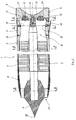
- FIG. 1 shows the front part and the rear part of a projectile 1 of the self-propelled type with ramjet.
- This projectile comprises an envelope 2, made of a light material of the composite type (for example a carbon-epoxy), and a penetrator 3 made of heavy material such as tungsten.
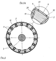
- the penetrator 3 is arranged coaxially with the casing 2, and it is made integral by a tubular element 26, (see Figure 2), also made of carbon-epoxy, and which extends over substantially the entire length of the envelope.
- This element comprises an external tube 27, glued to the internal surface of the envelope, and an internal tube 28 glued to the indenter, these two tubes being connected by ribs 7, here four in number (see Figure 2), which thus delimit four chambers between the indenter and the envelope.
- a propellant charge 5 is placed inside the chambers. This charge is of the propellant type ablatable.
- An annular space 25 is provided between the propellant charge and the penetrator, this in order to allow the flow of air inside the ramjet.
- the ribs have only a support function for the penetrator and they may include openings (not shown) making the chambers communicate with each other, this in order to regulate the combustion of the propellant charge 5.
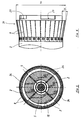
- the front part (or hull) 8 of the casing 2, (which is made of carbon-epoxy), is supported by four other ribs (see Figure 3), on a nose 4 secured to the front part of the indenter (by example by collage).
- the nose 4 and the hull 8 define an annular opening 17 for air intake.
- the particular shape of the nose 4 ending in a point 22 is designed (in a known manner) so that the shock wave coming from the point during the flight of the projectile at a supersonic speed has the effect of increasing the pressure air entering the annular opening 17.
- the internal rear part of the casing 2 will constitute a nozzle 16 for ejecting the gases.
- the projectile 1 carries at its rear part a shoe 6 which is made integral with the penetrator 3 by means of a connecting screw 14, a conical housing 23 ensuring correct positioning of the shoe and the penetrator.
- the connecting screw is dimensioned so as to break when, at the exit of the projectile from the barrel, the pressure exerted on the sabot at the level of the nozzle 16, becomes greater than that which is exerted on the back of the hoof.
- the shoe 6 carries on its external cylindrical surface a belt 11, which is intended to take the scratches from the barrel of the weapon and thus to achieve the sealing and the rotation of the projectile in a completely conventional manner.
- the shoe 6 is pierced with two holes 12 which make the internal part of the projectile communicate with the outside; it also carries, opposite the holes 12, ignition elements 13, which will for example include a ignition pyrotechnic composition associated with a delay composition (these compositions being of known type).
- ignition elements 13 which will for example include a ignition pyrotechnic composition associated with a delay composition (these compositions being of known type).
- these ignition elements are screwed into counterbores 21 having the same axis as the holes 12. The function of these elements will be specified below.
- the shoe 6 carries out the rotation of the envelope by means of four dogs 24 coming to cooperate with notches 29 (see FIG. 6) having a complementary shape and produced at the rear part of the envelope 2 of the projectile.
- the rear part of the envelope carries thirty tabs 9 (see Figure 4), which are made integral with the lateral surface of the envelope 2, by one of their ends, by means of screws 18. These tabs are fixed at level d 'a circular generator of the envelope and are regularly distributed on this generator.
- each tongue makes an angle ⁇ with the axis of the projectile.
- Figure 1 shows a tongue in the folded position and a tongue in the deployed position.
- the set of tongues forms a substantially conical skirt 31, the half-angle at the top of this cone being equal to ⁇ and the axis of the cone coinciding with that of the projectile.
- the free ends of the tongues are regularly distributed over the large base circle of this cone, a circle whose diameter is D (see Figure 6).
- the tongues are held in the folded position by an internal cylindrical surface 15 of the shoe 6 (see FIG. 5), they are therefore not projecting relative to the external surface of the envelope. They do not then risk being damaged by possible contact with the barrel of the weapon during the barrel phase.
- Each tongue carries two recesses 30 (see Figure 4a) whose shapes and relative arrangements are such that there is total covering of each tongue by one of its neighbors in the folded position and partial covering in the deployed position.
- one tongue out of two carries a lock 10, constituted by a shouldered rod 19 capable of sliding in a radial housing 20, arranged on the envelope, until contact with a counterbore made in this housing.
- the tongues provided with latches are immobilized by the latter, and they immobilize themselves the tongues devoid of latches by means of the recesses 30.
- each tongue is immobilized in the deployed position by a locking means which is here either the bolt 10, or the recess 30 carried by the neighboring tongue.
- Tabs and latches are made for example of steel and are dimensioned so as to guarantee good mechanical strength as well as the maintenance of the angular position deployed during the flight (speed of the projectile of the order of 1500 m / s, accelerations of l 34000 g).
- the projectile is placed in the chamber of a weapon and is fired in a conventional manner, the gas pressure exerted on the rear part of the shoe 6 pushes the projectile into the tube; the belt 11 takes the scratches, performs the seal and communicates a speed of rotation which will be of the order of 500 revolutions / second at the outlet of the barrel of the weapon.
- the pressure exerted at the rear of the shoe 6 is greater than that exerted on it at the level of the internal part of the projectile.
- At the outlet of the tube it is the internal pressure which becomes preponderant, causing the rupture of the connecting screw 14.
- the latter will be dimensioned in such a way that this rupture occurs in the first 100 meters traveled by the projectile.
- the gases could penetrate through the holes 12 inside the envelope and cause the initiation of the pyrotechnic ignition elements 13, these elements will make it possible to ignite the propellant charge 5.
- this ignition By playing on the characteristics of the delay composition and of the ignition composition it is possible to carry out this ignition at a completely controlled instant (preferably in the tenth of a second following the firing).
- the inertia of such a projectile relative to its axis is of the order of 10-2 kg.m2 (for a caliber of 105 mm, Tungsten penetrator, carbon-epoxy casing), and it is too low to ensure gyro-stabilization (for comparison, an explosive shell of the same caliber has an inertia of the order of 0.25 kg.m2).
- the use of a conventional tail unit is made impossible because of the very high speed of rotation communicated by the barrel tube (of the order of 500 revolutions / second), which would cause it to break.
- the thirty tongues of the stabilization device according to the invention are aerodynamically equivalent to a conical skirt disposed at the rear of the casing, the axis of the cone coinciding with the axis of the projectile.
- This skirt will cause a modification of the projectile drag and a decrease in absolute value of the static margin which will allow to obtain a stable trajectory.
- a projectile which does not rotate will be all the more stable as the focus of the aerodynamic forces will be further from the center of gravity and behind it (large static margin, at least equal to the caliber).
- a gyro-stabilized projectile will be all the more stable as its static margin will be lower in absolute value (the focus of the aerodynamic forces being in front of the center of gravity of the projectile).
- this stability is usually assessed by means of a coefficient, called the essential stability coefficient, which depends on the speed of rotation and on the geometry of the projectile.
- a projectile is gyrostabilized when this coefficient is greater than 1.5.
- a projectile with low longitudinal inertia (of the order of 10 -2 kg / m2) and not comprising the skirt proposed by the invention cannot be gyrostabilized. Indeed, the focus of aerodynamic forces is then too far from the center of gravity.
- the projectile of FIG. 1 (105 mm caliber), without the skirt according to the invention, has its aerodynamic focus situated on the axis of the projectile and substantially at the mid-height of the hull 8, c '' is to say approximately 240 mm in front of the center of gravity of the projectile, the essential coefficient of stability is then of the order of 0.5 and the projectile is unstable.
- This skirt will be positioned so as to ensure an essential coefficient of stability greater than 1.5. In practice, it will suffice to position it so that the base circle of the cone practically coincides with the rear of the envelope.
- the height of the skirt can be arbitrary, but it can however be noted that, for a value of constant angle, skirts whose height is too large will have a base diameter much greater than the diameter of the projectile which will cause an increase in drag and therefore a decrease in the range of the projectile.
- the skirt will be dimensioned so that, in its deployed position, the ratio of the diameter of the projectile envelope to that of the largest base circle of the cone of the skirt (D) is not less than 70% .
- a value between 5 ° and 15 ° will be chosen for the half-angle at the top of the cone of the skirt in order to reduce the drag caused by the latter.
- a ramjet projectile comprising a penetrator made of heavy material, such as tungsten, a projectile which can be fired from a striped tube.
- the ramjet thus makes it possible to obtain a projectile whose range or terminal efficiency is significantly increased compared to conventional arrow type projectiles.
- the device according to the invention also makes it possible to lighten the envelope which authorizes, at equal mass, the use of a heavier penetrator and further increases the terminal efficiency of the projectile.
- An advantage of the embodiment described above is that it makes it possible to simplify the production of the skirt according to the invention by approximating the continuous shape by a limited number of tongues.
- Wind tunnel tests have shown that a number N of tongues whose dimensions are such that, in their deployed position, the free ends of the tongues cover at least 70% of the largest base circle of the cone of the skirt, gives good aerodynamic approximation of the latter in the usual conditions for firing a large caliber projectile from a rifled tube.
- the tongues may be of a smaller number, it will be possible for example to provide four tongues having a substantially cylindrical profile so as to be able to adopt a folded position along the envelope, but having a cut such that their free end is wider than their end fixed to the envelope. There will still be an overlap of the tongues in the folded and deployed positions, the shape of the skirt obtained being substantially conical.
- shouldered rod 19 and the radial housing 20 may be conical, the conicity ensuring locking in the deployed position.
- the use of the stabilization device according to the invention for a ramjet-type projectile will make it possible to obtain (as noted in the preamble) the best cost-effectiveness compromise.
Landscapes
- Physics & Mathematics (AREA)
- Fluid Mechanics (AREA)
- Engineering & Computer Science (AREA)
- General Engineering & Computer Science (AREA)
- Aiming, Guidance, Guns With A Light Source, Armor, Camouflage, And Targets (AREA)
- Load-Engaging Elements For Cranes (AREA)
- Placing Or Removing Of Piles Or Sheet Piles, Or Accessories Thereof (AREA)
- Shaping By String And By Release Of Stress In Plastics And The Like (AREA)
- Details Of Aerials (AREA)
- Toys (AREA)
Claims (9)
- Stabilisierungsvorrichtung für ein Geschoß (1) mit Nachbeschleunigung und geringem Längsträgheitsmoment, im besonderen für ein Geschoß mit einer Einlage (3) aus einem schweren Material, wie z.B. Wolfram, und einer Hülle (2) aus einem leichten Verbundwerkstoff, wobei diese Vorrichtung eine Schürze (31) aufweist, die die allgemeine Form eines Kegelstumpfes besitzt, und wobei die Achse des Kegelstumpfes mit der Achse des Geschosses (1) übereinstimmt, die Schürze mit der Hülle (2) auf der Höhe des hinteren Geschoßteils fest verbunden ist, und die dadurch gekennzeichnet ist, daß die Stabilisierungsvorrichtung aus einer Anzahl von Streifen besteht, die von einem Verbindungsmittel in eingeklappter Stellung gehalten werden, solange das Geschoß sich im Rohr der Waffe befindet, und die beim Austritt aus dem erwähnten Rohr aufklappen, wobei das Verbindungsmittel von einem Treibkäfig (6) gebildet wird, der während der Drehung mit der Hülle (2) verbunden ist, und dessen hinterer Teil den Gasdruck aufnimmt, um das Geschoß im Rohr entlang zu befördern, wobei sich der Treibkäfig am Ausgang des Waffenrohrs von der Hülle trennt, und das Geschoß dazu bestimmt ist, aus einem gezogenen Rohr verschossen zu werden.
- Stabilisierungsvorrichtung gemäß Patentanspruch 1, dadurch gekennzeichnet, daß jeder Streifen mit einer Verriegelungsvorrichtung verbunden ist, die aus einem Zentrifugalriegel (10) in einer radialen Aussparung (20) der Hülle (2) besteht.
- Stabilisierungsvorrichtung gemäß Patentanspruch 2, dadurch gekennzeichnet, daß der Zentrifugalriegel (10) von einem sich nach oben verdickenden Stift (19) gebildet wird.
- Stabilisierungsvorrichtung gemäß einem der Patentansprüche 1 bis 3, dadurch gekennzeichnet, daß die Streifen (9) jeweils eine Kerbe (30) auf der Höhe ihrer Längsgrate aufweisen, damit sie auf der Höhe ihrer Verbindungsstellen übereinanderliegen.
- Stabilisierungsvorrichtung gemäß einem der Patentansprüche 1 bis 4, dadurch gekennzeichnet, daß der Treibkäfig (6) mindestens ein Loch (12) aufweist, wodurch eine Verbindung des Geschoßinneren nach außen hergestellt wird.
- Stabilisierungsvorrichtung gemäß Patentanspruch 5, dadurch gekennzeichnet, daß der Treibkäfig (6) gegenüber den Löchern (12) auf der Höhe des hinteren Geschoßteils ein pyrotechnisches Zündungselement (13) aufweist.
- Stabilisierungsvorrichtung gemäß Patentanspruch 5 oder 6, dadurch gekennzeichnet, daß der Treibkäfig (6) auf der Höhe der Einlage (3) fest mit dem Geschoß (1) verbunden ist.
- Stabilisierungsvorrichtung gemäß einem der Patentansprüche 1 bis 7, dadurch gekennzeichnet, daß der Halbwinkel an der Spitze des Kegelstumpfes der Schürze (31) zwischen 5° und 15° liegt, wenn sich diese in aufgeklappter Stellung befindet, sowie dadurch, daß das Verhältnis des äußeren Durchmessers der Hülle (2) zum Durchmesser (D) des größten Grundkreises des Kegelstumpfes der Schürze (31) gleich bzw. größer als 70 % ist.
- Stabilisierungsvorrichtung gemäß einem der Patentansprüche 1 bis 7, dadurch gekennzeichnet, daß die Streifen (9) auf der Höhe einer kreisförmigen Mantellinie der Hülle fest mit einem Ende der Hülle (2) verbunden und längs dieser Mantellinie regelmäßig verteilt sind, wobei die Anzahl N und die Breite der Streifen so gewählt werden, daß ihre freien Enden in aufgeklappter Stellung mindestens 70 % des größten Grundkreises des Kegelstumpfes der Schürze (31) abdecken.
Priority Applications (1)
| Application Number | Priority Date | Filing Date | Title |
|---|---|---|---|
| AT89400872T ATE98366T1 (de) | 1988-03-31 | 1989-03-29 | Stabilisierungsvorrichtung fuer geschosse von gezogenen laeufen. |
Applications Claiming Priority (2)
| Application Number | Priority Date | Filing Date | Title |
|---|---|---|---|
| FR8804257 | 1988-03-31 | ||
| FR8804257A FR2629584B1 (fr) | 1988-03-31 | 1988-03-31 | Dispositif de stabilisation pour un projectile a faible moment d'inertie longitudinal tire a partir d'un tube raye |
Publications (2)
| Publication Number | Publication Date |
|---|---|
| EP0338879A1 EP0338879A1 (de) | 1989-10-25 |
| EP0338879B1 true EP0338879B1 (de) | 1993-12-08 |
Family
ID=9364828
Family Applications (1)
| Application Number | Title | Priority Date | Filing Date |
|---|---|---|---|
| EP89400872A Expired - Lifetime EP0338879B1 (de) | 1988-03-31 | 1989-03-29 | Stabilisierungsvorrichtung für Geschosse von gezogenen Läufen |
Country Status (5)
| Country | Link |
|---|---|
| EP (1) | EP0338879B1 (de) |
| AT (1) | ATE98366T1 (de) |
| DE (1) | DE68911191T2 (de) |
| ES (1) | ES2048299T3 (de) |
| FR (1) | FR2629584B1 (de) |
Families Citing this family (2)
| Publication number | Priority date | Publication date | Assignee | Title |
|---|---|---|---|---|
| ATE493126T1 (de) | 2001-11-01 | 2011-01-15 | Spectrum Pharmaceuticals Inc | Medizinische zusammensetzungen zur intravesikalen behandlung von blasenkrebs |
| FR3080912B1 (fr) | 2018-05-02 | 2020-04-03 | Nexter Munitions | Projectile propulse par statoreacteur |
Family Cites Families (6)
| Publication number | Priority date | Publication date | Assignee | Title |
|---|---|---|---|---|
| US3081703A (en) * | 1958-07-29 | 1963-03-19 | Ewald A Kamp | Spin-cone stabilized projectile |
| DE1290453B (de) * | 1966-01-31 | 1969-03-06 | Entwicklungsring Sued Gmbh | Lenkbares Geschoss mit Eigenantrieb fuer UEberschallgeschwindigkeit |
| US3589293A (en) * | 1968-12-03 | 1971-06-29 | Emery Major | Explosive device comprising separate hollow bodies with glycerin and nitric acid therein |
| DE2637793C2 (de) * | 1976-08-21 | 1983-11-17 | Messerschmitt-Bölkow-Blohm GmbH, 8000 München | Vorrichtung zur Verminderung der Fluggeschwindigkeit und zur Stabilisierung der Lage einer Streumunition |
| US4143838A (en) * | 1977-08-22 | 1979-03-13 | The United States Of America As Represented By The Secretary Of The Navy | Folding fin assembly detent |
| US4573412A (en) * | 1984-04-27 | 1986-03-04 | The United States Of America As Represented By The Secretary Of The Army | Plug nozzle kinetic energy penetrator rocket |
-
1988
- 1988-03-31 FR FR8804257A patent/FR2629584B1/fr not_active Expired - Fee Related
-
1989
- 1989-03-29 ES ES89400872T patent/ES2048299T3/es not_active Expired - Lifetime
- 1989-03-29 DE DE68911191T patent/DE68911191T2/de not_active Expired - Fee Related
- 1989-03-29 EP EP89400872A patent/EP0338879B1/de not_active Expired - Lifetime
- 1989-03-29 AT AT89400872T patent/ATE98366T1/de not_active IP Right Cessation
Also Published As
| Publication number | Publication date |
|---|---|
| FR2629584B1 (fr) | 1993-06-04 |
| EP0338879A1 (de) | 1989-10-25 |
| DE68911191D1 (de) | 1994-01-20 |
| FR2629584A1 (fr) | 1989-10-06 |
| DE68911191T2 (de) | 1994-05-19 |
| ES2048299T3 (es) | 1994-03-16 |
| ATE98366T1 (de) | 1993-12-15 |
Similar Documents
| Publication | Publication Date | Title |
|---|---|---|
| EP0905473B1 (de) | Grosskalibriges und weitreichendes Artilleriegeschoss | |
| EP0346214B1 (de) | Verfahren und Vorrichtung zum Auswerfen von Submunition | |
| EP1045221B1 (de) | Bremsvorrichtung für die Flugbahngeschwindigkeit eines Geschosses | |
| FR2599828A1 (fr) | Munition de petit ou moyen calibre a efficacite amelioree et portee limitee, en particulier pour la chasse | |
| EP0180515A1 (de) | Einrichtung zum Reduzieren des Luftwiderstandes von Munition und damit versehene Munition | |
| FR2478297A1 (fr) | Perfectionnements apportes aux tetes militaires, notamment antichars, agissant en survol d'un objectif ou d'un groupe d'objectifs | |
| EP1006335A1 (de) | Bremsvorrichtung für die Flugbahngeschwindigkeit eines Geschosses | |
| EP0048644B1 (de) | Geschoss mit Leitflossen in Gestalt eines Pfeiles | |
| EP0143720A1 (de) | Munition für Jagdgewehr | |
| EP0659264B1 (de) | Vorrichtung zur abdichtung der teribgase bei artilleriegeschossen | |
| EP0338879B1 (de) | Stabilisierungsvorrichtung für Geschosse von gezogenen Läufen | |
| FR2662240A1 (fr) | Projectiles penetrants. | |
| EP0918205B1 (de) | Projektil mit radialer Wirkrichtung | |
| EP3788249B1 (de) | Projektil mit staustrahltriebwerk | |
| EP0178959B1 (de) | Weittragendes Artilleriegeschoss | |
| EP0811823A1 (de) | Explosives Geschoss | |
| EP1712873A1 (de) | Adapter für ein Mörsergeschoss in einem Geschützlauf | |
| FR2595810A1 (fr) | Perfectionnements apportes aux munitions a sous-munitions pour attaque de zone | |
| EP0759533B1 (de) | Panzerbrechendes Geschoss und mit einem solchen Geschoss versehene Munition | |
| EP4589243A1 (de) | Leitwerkstabilisiertes artilleriegeschoss mit einer leitwerkschutzverkleidung, die durch entnahme von treibladungsgasen abgeworfen werden kann | |
| FR2947046A1 (fr) | Tete militaire comportant des moyens de marquage de cible | |
| FR2657157A1 (fr) | Dispositif de correction de courbure d'un trajectoire d'une munition perforante pour des cibles a haute resistance mecanique. | |
| FR2821420A1 (fr) | Ogive perforante autopropulsee pour tir tendu longue portee | |
| FR2572513A1 (fr) | Dispositif pour corriger l'orientation d'une munition | |
| FR2698163A1 (fr) | Projectile de perforation et munition équipée d'un tel projectile. |
Legal Events
| Date | Code | Title | Description |
|---|---|---|---|
| PUAI | Public reference made under article 153(3) epc to a published international application that has entered the european phase |
Free format text: ORIGINAL CODE: 0009012 |
|
| 17P | Request for examination filed |
Effective date: 19890405 |
|
| AK | Designated contracting states |
Kind code of ref document: A1 Designated state(s): AT BE CH DE ES GB IT LI NL SE |
|
| RAP1 | Party data changed (applicant data changed or rights of an application transferred) |
Owner name: GIAT INDUSTRIES |
|
| 17Q | First examination report despatched |
Effective date: 19920715 |
|
| GRAA | (expected) grant |
Free format text: ORIGINAL CODE: 0009210 |
|
| AK | Designated contracting states |
Kind code of ref document: B1 Designated state(s): AT BE CH DE ES GB IT LI NL SE |
|
| REF | Corresponds to: |
Ref document number: 98366 Country of ref document: AT Date of ref document: 19931215 Kind code of ref document: T |
|
| REF | Corresponds to: |
Ref document number: 68911191 Country of ref document: DE Date of ref document: 19940120 |
|
| ITF | It: translation for a ep patent filed | ||
| GBT | Gb: translation of ep patent filed (gb section 77(6)(a)/1977) |
Effective date: 19940210 |
|
| REG | Reference to a national code |
Ref country code: ES Ref legal event code: FG2A Ref document number: 2048299 Country of ref document: ES Kind code of ref document: T3 |
|
| PLBE | No opposition filed within time limit |
Free format text: ORIGINAL CODE: 0009261 |
|
| STAA | Information on the status of an ep patent application or granted ep patent |
Free format text: STATUS: NO OPPOSITION FILED WITHIN TIME LIMIT |
|
| 26N | No opposition filed | ||
| EAL | Se: european patent in force in sweden |
Ref document number: 89400872.1 |
|
| PGFP | Annual fee paid to national office [announced via postgrant information from national office to epo] |
Ref country code: CH Payment date: 19960305 Year of fee payment: 8 |
|
| PGFP | Annual fee paid to national office [announced via postgrant information from national office to epo] |
Ref country code: SE Payment date: 19960311 Year of fee payment: 8 |
|
| PGFP | Annual fee paid to national office [announced via postgrant information from national office to epo] |
Ref country code: ES Payment date: 19960314 Year of fee payment: 8 |
|
| PGFP | Annual fee paid to national office [announced via postgrant information from national office to epo] |
Ref country code: GB Payment date: 19960319 Year of fee payment: 8 |
|
| PGFP | Annual fee paid to national office [announced via postgrant information from national office to epo] |
Ref country code: DE Payment date: 19960328 Year of fee payment: 8 Ref country code: AT Payment date: 19960328 Year of fee payment: 8 |
|
| PGFP | Annual fee paid to national office [announced via postgrant information from national office to epo] |
Ref country code: NL Payment date: 19960331 Year of fee payment: 8 |
|
| PGFP | Annual fee paid to national office [announced via postgrant information from national office to epo] |
Ref country code: BE Payment date: 19960412 Year of fee payment: 8 |
|
| PG25 | Lapsed in a contracting state [announced via postgrant information from national office to epo] |
Ref country code: GB Effective date: 19970329 Ref country code: AT Effective date: 19970329 |
|
| PG25 | Lapsed in a contracting state [announced via postgrant information from national office to epo] |
Ref country code: SE Effective date: 19970330 |
|
| PG25 | Lapsed in a contracting state [announced via postgrant information from national office to epo] |
Ref country code: ES Free format text: LAPSE BECAUSE OF NON-PAYMENT OF DUE FEES Effective date: 19970331 Ref country code: CH Effective date: 19970331 Ref country code: BE Effective date: 19970331 Ref country code: LI Effective date: 19970331 |
|
| BERE | Be: lapsed |
Owner name: GIAT INDUSTRIES Effective date: 19970331 |
|
| PG25 | Lapsed in a contracting state [announced via postgrant information from national office to epo] |
Ref country code: NL Effective date: 19971001 |
|
| REG | Reference to a national code |
Ref country code: CH Ref legal event code: PL |
|
| GBPC | Gb: european patent ceased through non-payment of renewal fee |
Effective date: 19970329 |
|
| NLV4 | Nl: lapsed or anulled due to non-payment of the annual fee |
Effective date: 19971001 |
|
| PG25 | Lapsed in a contracting state [announced via postgrant information from national office to epo] |
Ref country code: DE Effective date: 19971202 |
|
| EUG | Se: european patent has lapsed |
Ref document number: 89400872.1 |
|
| REG | Reference to a national code |
Ref country code: ES Ref legal event code: FD2A Effective date: 19990503 |
|
| PG25 | Lapsed in a contracting state [announced via postgrant information from national office to epo] |
Ref country code: IT Free format text: LAPSE BECAUSE OF NON-PAYMENT OF DUE FEES;WARNING: LAPSES OF ITALIAN PATENTS WITH EFFECTIVE DATE BEFORE 2007 MAY HAVE OCCURRED AT ANY TIME BEFORE 2007. THE CORRECT EFFECTIVE DATE MAY BE DIFFERENT FROM THE ONE RECORDED. Effective date: 20050329 |