EP0338879B1 - Stabilizing means for projectile to be fired from a rifled barrel - Google Patents
Stabilizing means for projectile to be fired from a rifled barrel Download PDFInfo
- Publication number
- EP0338879B1 EP0338879B1 EP89400872A EP89400872A EP0338879B1 EP 0338879 B1 EP0338879 B1 EP 0338879B1 EP 89400872 A EP89400872 A EP 89400872A EP 89400872 A EP89400872 A EP 89400872A EP 0338879 B1 EP0338879 B1 EP 0338879B1
- Authority
- EP
- European Patent Office
- Prior art keywords
- projectile
- skirt
- fact
- casing
- barrel
- Prior art date
- Legal status (The legal status is an assumption and is not a legal conclusion. Google has not performed a legal analysis and makes no representation as to the accuracy of the status listed.)
- Expired - Lifetime
Links
- 230000000087 stabilizing effect Effects 0.000 title description 2
- 210000002105 tongue Anatomy 0.000 claims description 29
- 230000006641 stabilisation Effects 0.000 claims description 26
- 239000007789 gas Substances 0.000 claims description 12
- 239000000463 material Substances 0.000 claims description 9
- 239000002131 composite material Substances 0.000 claims description 6
- WFKWXMTUELFFGS-UHFFFAOYSA-N tungsten Chemical compound [W] WFKWXMTUELFFGS-UHFFFAOYSA-N 0.000 claims description 6
- 229910052721 tungsten Inorganic materials 0.000 claims description 6
- 239000010937 tungsten Substances 0.000 claims description 6
- 239000003562 lightweight material Substances 0.000 claims 1
- 230000003019 stabilising effect Effects 0.000 abstract 3
- 239000003380 propellant Substances 0.000 description 18
- 238000011105 stabilization Methods 0.000 description 17
- 230000005484 gravity Effects 0.000 description 10
- 238000002485 combustion reaction Methods 0.000 description 7
- 239000000203 mixture Substances 0.000 description 7
- 230000003068 static effect Effects 0.000 description 5
- 239000004593 Epoxy Substances 0.000 description 4
- 230000000694 effects Effects 0.000 description 3
- 238000010304 firing Methods 0.000 description 3
- 239000007800 oxidant agent Substances 0.000 description 2
- 230000001590 oxidative effect Effects 0.000 description 2
- 238000000926 separation method Methods 0.000 description 2
- 239000004449 solid propellant Substances 0.000 description 2
- 241000282472 Canis lupus familiaris Species 0.000 description 1
- 235000015842 Hesperis Nutrition 0.000 description 1
- 235000012633 Iberis amara Nutrition 0.000 description 1
- 229910000831 Steel Inorganic materials 0.000 description 1
- 238000002679 ablation Methods 0.000 description 1
- 230000001133 acceleration Effects 0.000 description 1
- 230000003466 anti-cipated effect Effects 0.000 description 1
- 239000003638 chemical reducing agent Substances 0.000 description 1
- 230000000295 complement effect Effects 0.000 description 1
- 230000006866 deterioration Effects 0.000 description 1
- 239000002360 explosive Substances 0.000 description 1
- 239000011152 fibreglass Substances 0.000 description 1
- 239000000446 fuel Substances 0.000 description 1
- 210000000003 hoof Anatomy 0.000 description 1
- 230000000977 initiatory effect Effects 0.000 description 1
- 238000002955 isolation Methods 0.000 description 1
- 238000012423 maintenance Methods 0.000 description 1
- 238000004519 manufacturing process Methods 0.000 description 1
- 238000012986 modification Methods 0.000 description 1
- 230000004048 modification Effects 0.000 description 1
- 238000007789 sealing Methods 0.000 description 1
- 230000035939 shock Effects 0.000 description 1
- 239000007787 solid Substances 0.000 description 1
- 239000010959 steel Substances 0.000 description 1
Images

Classifications
-
- F—MECHANICAL ENGINEERING; LIGHTING; HEATING; WEAPONS; BLASTING
- F42—AMMUNITION; BLASTING
- F42B—EXPLOSIVE CHARGES, e.g. FOR BLASTING, FIREWORKS, AMMUNITION
- F42B10/00—Means for influencing, e.g. improving, the aerodynamic properties of projectiles or missiles; Arrangements on projectiles or missiles for stabilising, steering, range-reducing, range-increasing or fall-retarding
- F42B10/02—Stabilising arrangements
- F42B10/14—Stabilising arrangements using fins spread or deployed after launch, e.g. after leaving the barrel
Definitions
- the present invention relates to a stabilization device for a projectile, intended to be fired from a rifled tube, and having a small longitudinal moment of inertia, for example a self-propelled projectile comprising a penetrator of heavy material, such as tungsten, and an envelope of light material, of the composite type.
- Rocket propulsion in which the projectile carries a propellant charge, of the solid or homogeneous solid propellant type, generating a gas pressure at its rear.
- This first mode of self-propulsion is used for example for rockets and also in certain artillery shells (see patent FR2522134); it then significantly increases the range.
- the propulsion by ramjet uses a propellant load of the solid propellant type ablatable or autopyrolisable arranged inside an envelope comprising an air intake opening at the front of the projectile and an outlet nozzle.
- the air admitted at high flight speeds is slowed down in an inlet diffuser and enters the combustion chamber in the form of compressed air.
- the combustion of the mixture of air (oxidant) with the gas (reducing agent) obtained by autopyrolysis or ablation of the propellant block provides energy which is transformed into propelling force in the thrust nozzle.
- This type of self-propulsion has a certain number of advantages compared to the rocket self-propulsion mode.
- the pressures developed in the combustion chamber are lower (3.106 to 6.106 Pa for the ramjet versus 7.106 to 25.106 Pa for the rocket propellant), which simplifies the mechanical design of the projectile.
- the patent US2989922 describes a ramjet projectile intended to be fired by a cannon.
- This projectile comprises a military charge surrounded by a propellant composition, itself arranged inside a tubular envelope carrying a belt.
- This projectile is gyrostabilized in a conventional manner, the belt taking the scratches from the barrel of the weapon.
- Such a stabilization mode is possible because of the large longitudinal moments of inertia of the military load and the envelope.
- the patent US4573412 shows such a projectile comprising a penetrator held in an envelope made of composite material of the fiberglass type.
- This projectile is intended to be fired from a light tube and at reduced initial speed.
- the mass of the penetrator is here less than that of the arrow type penetrators used in artillery, a reduction in perforation performance is ensured.
- Another solution making it possible to fire a projectile at a low longitudinal moment of inertia from a striped tube consists in providing it with a slip belt (like that described by patent FR8616066), the stabilization device then being constituted by a conventional tailplane.
- US-A-3 081 703 describing a stabilization device for a rotating projectile, comprising a cone held in the folded position when the projectile is inside the launching tube and deploying at the exit of this tube.
- the projectile described is of the self-propelled rocket type, the rotation being obtained by means of gas deflectors.
- the launching tube is thus a smooth guide tube and the projectile is therefore not subjected to a canon environment.
- the fins include a means for holding in the folded position which is a combustible star; this star is burned by the gases ejected by the projectile.
- the object of the present invention is to provide a projectile stabilization device associating a heavy material penetrator and a light casing fired from a conventional artillery weapon comprising a striped tube, in which the stabilization skirt is protected. folded position during the gun phase.
- the subject of the invention is therefore a stabilization device for a self-propelled projectile with low longitudinal moment of inertia, in particular for a projectile comprising a penetrator of heavy material, such as tungsten, and an envelope of light material of the composite type, device comprising a skirt of generally frustoconical shape, the axis of the truncated cone coinciding with the axis of the projectile , the skirt being integral with the envelope at the rear part of the projectile, characterized in that the skirt consists of a set of tongues maintained in a folded position by a connecting means when the projectile is in the tube the weapon, which deploys at the outlet of said tube, the connection means being constituted by a shoe linked in rotation to the casing and receiving the gas pressure at its rear part so as to push the projectile into the tube, the sabot separating from the envelope at the outlet of the barrel, the projectile being intended to be fired by a rifled tube.
- Each tab can be connected to a locking means in position constituted by a centrifugal lock engaged in a radial housing formed in the envelope.
- the centrifugal lock can be constituted by a shouldered rod.
- the tongues each have an entanglement at their longitudinal edges so as to provide an overlap at their junction.
- the shoe carries at least one hole communicating the internal part of the projectile with the outside.
- the shoe carries opposite the holes and at the internal part of the projectile, a pyrotechnic ignition element.
- the shoe is made integral with the projectile at the level of the indenter.
- the half-angle at the top of the truncated cone of the skirt is between 5 ° and 15 ° when the latter is in the deployed position, and the ratio of the outside diameter of the envelope to the diameter (D) of the largest circle of base of the truncated cone of the skirt is greater than or equal to 70%.
- the tongues are secured at one end of the envelope at a circular generator of the envelope and are regularly distributed along this generator, the number N and the width of the tongues being such that in their deployed position their free ends cover at least 70% of the largest base circle of the trunk of the skirt cone.
- An advantage of the present invention lies in the fact that the tongues are kept in the folded position during the entire barrel phase.
- Another advantage lies in the isolation of the tongues by the shoe from the propellant gases in the barrel.
- Another advantage lies in the automatic deployment of the tabs in the deployed position.
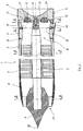
- FIG. 1 shows the front part and the rear part of a projectile 1 of the self-propelled type with ramjet.
- This projectile comprises an envelope 2, made of a light material of the composite type (for example a carbon-epoxy), and a penetrator 3 made of heavy material such as tungsten.
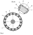
- the penetrator 3 is arranged coaxially with the casing 2, and it is made integral by a tubular element 26, (see Figure 2), also made of carbon-epoxy, and which extends over substantially the entire length of the envelope.
- This element comprises an external tube 27, glued to the internal surface of the envelope, and an internal tube 28 glued to the indenter, these two tubes being connected by ribs 7, here four in number (see Figure 2), which thus delimit four chambers between the indenter and the envelope.
- a propellant charge 5 is placed inside the chambers. This charge is of the propellant type ablatable.
- An annular space 25 is provided between the propellant charge and the penetrator, this in order to allow the flow of air inside the ramjet.
- the ribs have only a support function for the penetrator and they may include openings (not shown) making the chambers communicate with each other, this in order to regulate the combustion of the propellant charge 5.
- the front part (or hull) 8 of the casing 2, (which is made of carbon-epoxy), is supported by four other ribs (see Figure 3), on a nose 4 secured to the front part of the indenter (by example by collage).
- the nose 4 and the hull 8 define an annular opening 17 for air intake.
- the particular shape of the nose 4 ending in a point 22 is designed (in a known manner) so that the shock wave coming from the point during the flight of the projectile at a supersonic speed has the effect of increasing the pressure air entering the annular opening 17.
- the internal rear part of the casing 2 will constitute a nozzle 16 for ejecting the gases.
- the projectile 1 carries at its rear part a shoe 6 which is made integral with the penetrator 3 by means of a connecting screw 14, a conical housing 23 ensuring correct positioning of the shoe and the penetrator.
- the connecting screw is dimensioned so as to break when, at the exit of the projectile from the barrel, the pressure exerted on the sabot at the level of the nozzle 16, becomes greater than that which is exerted on the back of the hoof.
- the shoe 6 carries on its external cylindrical surface a belt 11, which is intended to take the scratches from the barrel of the weapon and thus to achieve the sealing and the rotation of the projectile in a completely conventional manner.
- the shoe 6 is pierced with two holes 12 which make the internal part of the projectile communicate with the outside; it also carries, opposite the holes 12, ignition elements 13, which will for example include a ignition pyrotechnic composition associated with a delay composition (these compositions being of known type).
- ignition elements 13 which will for example include a ignition pyrotechnic composition associated with a delay composition (these compositions being of known type).
- these ignition elements are screwed into counterbores 21 having the same axis as the holes 12. The function of these elements will be specified below.
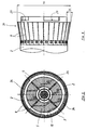
- the shoe 6 carries out the rotation of the envelope by means of four dogs 24 coming to cooperate with notches 29 (see FIG. 6) having a complementary shape and produced at the rear part of the envelope 2 of the projectile.
- the rear part of the envelope carries thirty tabs 9 (see Figure 4), which are made integral with the lateral surface of the envelope 2, by one of their ends, by means of screws 18. These tabs are fixed at level d 'a circular generator of the envelope and are regularly distributed on this generator.
- each tongue makes an angle ⁇ with the axis of the projectile.
- Figure 1 shows a tongue in the folded position and a tongue in the deployed position.
- the set of tongues forms a substantially conical skirt 31, the half-angle at the top of this cone being equal to ⁇ and the axis of the cone coinciding with that of the projectile.
- the free ends of the tongues are regularly distributed over the large base circle of this cone, a circle whose diameter is D (see Figure 6).
- the tongues are held in the folded position by an internal cylindrical surface 15 of the shoe 6 (see FIG. 5), they are therefore not projecting relative to the external surface of the envelope. They do not then risk being damaged by possible contact with the barrel of the weapon during the barrel phase.
- Each tongue carries two recesses 30 (see Figure 4a) whose shapes and relative arrangements are such that there is total covering of each tongue by one of its neighbors in the folded position and partial covering in the deployed position.
- one tongue out of two carries a lock 10, constituted by a shouldered rod 19 capable of sliding in a radial housing 20, arranged on the envelope, until contact with a counterbore made in this housing.
- the tongues provided with latches are immobilized by the latter, and they immobilize themselves the tongues devoid of latches by means of the recesses 30.
- each tongue is immobilized in the deployed position by a locking means which is here either the bolt 10, or the recess 30 carried by the neighboring tongue.
- Tabs and latches are made for example of steel and are dimensioned so as to guarantee good mechanical strength as well as the maintenance of the angular position deployed during the flight (speed of the projectile of the order of 1500 m / s, accelerations of l 34000 g).
- the projectile is placed in the chamber of a weapon and is fired in a conventional manner, the gas pressure exerted on the rear part of the shoe 6 pushes the projectile into the tube; the belt 11 takes the scratches, performs the seal and communicates a speed of rotation which will be of the order of 500 revolutions / second at the outlet of the barrel of the weapon.
- the pressure exerted at the rear of the shoe 6 is greater than that exerted on it at the level of the internal part of the projectile.
- At the outlet of the tube it is the internal pressure which becomes preponderant, causing the rupture of the connecting screw 14.
- the latter will be dimensioned in such a way that this rupture occurs in the first 100 meters traveled by the projectile.
- the gases could penetrate through the holes 12 inside the envelope and cause the initiation of the pyrotechnic ignition elements 13, these elements will make it possible to ignite the propellant charge 5.
- this ignition By playing on the characteristics of the delay composition and of the ignition composition it is possible to carry out this ignition at a completely controlled instant (preferably in the tenth of a second following the firing).
- the inertia of such a projectile relative to its axis is of the order of 10-2 kg.m2 (for a caliber of 105 mm, Tungsten penetrator, carbon-epoxy casing), and it is too low to ensure gyro-stabilization (for comparison, an explosive shell of the same caliber has an inertia of the order of 0.25 kg.m2).
- the use of a conventional tail unit is made impossible because of the very high speed of rotation communicated by the barrel tube (of the order of 500 revolutions / second), which would cause it to break.
- the thirty tongues of the stabilization device according to the invention are aerodynamically equivalent to a conical skirt disposed at the rear of the casing, the axis of the cone coinciding with the axis of the projectile.
- This skirt will cause a modification of the projectile drag and a decrease in absolute value of the static margin which will allow to obtain a stable trajectory.
- a projectile which does not rotate will be all the more stable as the focus of the aerodynamic forces will be further from the center of gravity and behind it (large static margin, at least equal to the caliber).
- a gyro-stabilized projectile will be all the more stable as its static margin will be lower in absolute value (the focus of the aerodynamic forces being in front of the center of gravity of the projectile).
- this stability is usually assessed by means of a coefficient, called the essential stability coefficient, which depends on the speed of rotation and on the geometry of the projectile.
- a projectile is gyrostabilized when this coefficient is greater than 1.5.
- a projectile with low longitudinal inertia (of the order of 10 -2 kg / m2) and not comprising the skirt proposed by the invention cannot be gyrostabilized. Indeed, the focus of aerodynamic forces is then too far from the center of gravity.
- the projectile of FIG. 1 (105 mm caliber), without the skirt according to the invention, has its aerodynamic focus situated on the axis of the projectile and substantially at the mid-height of the hull 8, c '' is to say approximately 240 mm in front of the center of gravity of the projectile, the essential coefficient of stability is then of the order of 0.5 and the projectile is unstable.
- This skirt will be positioned so as to ensure an essential coefficient of stability greater than 1.5. In practice, it will suffice to position it so that the base circle of the cone practically coincides with the rear of the envelope.
- the height of the skirt can be arbitrary, but it can however be noted that, for a value of constant angle, skirts whose height is too large will have a base diameter much greater than the diameter of the projectile which will cause an increase in drag and therefore a decrease in the range of the projectile.
- the skirt will be dimensioned so that, in its deployed position, the ratio of the diameter of the projectile envelope to that of the largest base circle of the cone of the skirt (D) is not less than 70% .
- a value between 5 ° and 15 ° will be chosen for the half-angle at the top of the cone of the skirt in order to reduce the drag caused by the latter.
- a ramjet projectile comprising a penetrator made of heavy material, such as tungsten, a projectile which can be fired from a striped tube.
- the ramjet thus makes it possible to obtain a projectile whose range or terminal efficiency is significantly increased compared to conventional arrow type projectiles.
- the device according to the invention also makes it possible to lighten the envelope which authorizes, at equal mass, the use of a heavier penetrator and further increases the terminal efficiency of the projectile.
- An advantage of the embodiment described above is that it makes it possible to simplify the production of the skirt according to the invention by approximating the continuous shape by a limited number of tongues.
- Wind tunnel tests have shown that a number N of tongues whose dimensions are such that, in their deployed position, the free ends of the tongues cover at least 70% of the largest base circle of the cone of the skirt, gives good aerodynamic approximation of the latter in the usual conditions for firing a large caliber projectile from a rifled tube.
- the tongues may be of a smaller number, it will be possible for example to provide four tongues having a substantially cylindrical profile so as to be able to adopt a folded position along the envelope, but having a cut such that their free end is wider than their end fixed to the envelope. There will still be an overlap of the tongues in the folded and deployed positions, the shape of the skirt obtained being substantially conical.
- shouldered rod 19 and the radial housing 20 may be conical, the conicity ensuring locking in the deployed position.
- the use of the stabilization device according to the invention for a ramjet-type projectile will make it possible to obtain (as noted in the preamble) the best cost-effectiveness compromise.
Landscapes
- Physics & Mathematics (AREA)
- Fluid Mechanics (AREA)
- Engineering & Computer Science (AREA)
- General Engineering & Computer Science (AREA)
- Aiming, Guidance, Guns With A Light Source, Armor, Camouflage, And Targets (AREA)
- Placing Or Removing Of Piles Or Sheet Piles, Or Accessories Thereof (AREA)
- Shaping By String And By Release Of Stress In Plastics And The Like (AREA)
- Load-Engaging Elements For Cranes (AREA)
- Details Of Aerials (AREA)
- Toys (AREA)
Abstract
Description
La présente invention concerne un dispositif de stabilisation pour un projectile, destiné à être tiré à partir d'un tube rayé, et présentant un faible moment d'inertie longitudinal, par exemple un projectile autopropulsé comprenant un pénétrateur en matériau lourd, tel le tungstène, et une enveloppe en matériau léger, de type composite.The present invention relates to a stabilization device for a projectile, intended to be fired from a rifled tube, and having a small longitudinal moment of inertia, for example a self-propelled projectile comprising a penetrator of heavy material, such as tungsten, and an envelope of light material, of the composite type.
Les projectiles autopropulsés sont connus depuis déjà quelques années. On peut distinguer deux modes d'autopropulsion:Self-propelled projectiles have been known for a few years already. We can distinguish two modes of self-propulsion:
La propulsion fusée, dans laquelle le projectile porte une charge propulsive, de type propergol solide composite ou homogène, générant une pression de gaz à sa partie arrière. Ce premier mode d'autopropulsion est utilisé par exemple pour les roquettes et également dans certains obus d'artillerie (voir brevet FR2522134) ; il permet alors d'accroître notablement la portée.Rocket propulsion, in which the projectile carries a propellant charge, of the solid or homogeneous solid propellant type, generating a gas pressure at its rear. This first mode of self-propulsion is used for example for rockets and also in certain artillery shells (see patent FR2522134); it then significantly increases the range.
La propulsion par statoréacteur utilise une charge propulsive de type propergol solide ablatable ou autopyrolisable disposée à l'intérieur d'une enveloppe comportant une ouverture d'admission d'air à l'avant du projectile et une tuyère de sortie. L'air admis aux grandes vitesses de vol est ralenti dans un diffuseur d'entrée et pénètre sous forme d'air comprimé dans la chambre de combustion. La combustion du mélange de l'air (oxydant) avec le gaz (réducteur) obtenu par autopyrolyse ou ablation du bloc de propergol apporte de l'énergie qui est transformée en force propulsive dans la tuyère de poussée.The propulsion by ramjet uses a propellant load of the solid propellant type ablatable or autopyrolisable arranged inside an envelope comprising an air intake opening at the front of the projectile and an outlet nozzle. The air admitted at high flight speeds is slowed down in an inlet diffuser and enters the combustion chamber in the form of compressed air. The combustion of the mixture of air (oxidant) with the gas (reducing agent) obtained by autopyrolysis or ablation of the propellant block provides energy which is transformed into propelling force in the thrust nozzle.
Ce type d'autopropulsion présente un certain nombre d'avantages par rapport au mode d'autopropulsion fusée.This type of self-propulsion has a certain number of advantages compared to the rocket self-propulsion mode.
Il permet en particulier (à portée égale) de minimiser la masse de propergol embarquée ; en, effet l'oxydant sera constitué par l'air admis dans la chambre de combustion.In particular, it allows (at equal reach) to minimize the weight of on-board propellant; in effect the oxidant will be constituted by the air admitted into the combustion chamber.
A performances égales, les pressions développées dans la chambre de combustion sont plus faibles (3.10⁶ à 6.10⁶ Pa pour le statoréacteur contre 7.10⁶ à 25.10⁶ Pa pour le propulseur fusée), ce qui permet de simplifier la conception mécanique du projectile.At equal performance, the pressures developed in the combustion chamber are lower (3.10⁶ to 6.10⁶ Pa for the ramjet versus 7.10⁶ to 25.10⁶ Pa for the rocket propellant), which simplifies the mechanical design of the projectile.
La consommation en combustible du statoréacteur aux vitesses supersoniques est réduite ce qui autorise de longues durées de vol.The fuel consumption of the ramjet at supersonic speeds is reduced, which allows long flight times.
Le brevet US2989922 décrit un projectile à statoréacteur destiné à être tiré par un canon. Ce projectile comporte une charge militaire entourée par une composition propulsive, elle même disposée à l'intérieur d'une enveloppe tubulaire portant une ceinture. Ce projectile est gyrostabilisé de façon conventionnelle, la ceinture prenant les rayures du tube de l'arme. Un tel mode de stabilisation est possible en raison des moments d'inertie longitudinaux important de la charge militaire et de l'enveloppe.The patent US2989922 describes a ramjet projectile intended to be fired by a cannon. This projectile comprises a military charge surrounded by a propellant composition, itself arranged inside a tubular envelope carrying a belt. This projectile is gyrostabilized in a conventional manner, the belt taking the scratches from the barrel of the weapon. Such a stabilization mode is possible because of the large longitudinal moments of inertia of the military load and the envelope.
Les blindages modernes pouvant être acquis par les projectiles à énergie cinétique (tel les projectiles flèches), il serait particulièrement intéressant de doter de tels projectiles d'une autopropulsion afin d'accroître leur portée et leur efficacité terminale tout en diminuant le temps de vol.As modern armor can be acquired by kinetic energy projectiles (such as arrow projectiles), it would be particularly advantageous to equip such projectiles with self-propulsion in order to increase their range and their terminal efficiency while reducing flight time.
Le brevet US4573412 montre un tel projectile comportant un pénétrateur maintenu dans une enveloppe en matériau composite du type fibre de verre.The patent US4573412 shows such a projectile comprising a penetrator held in an envelope made of composite material of the fiberglass type.
Ce projectile est destiné à être tiré à partir d'un tube léger et à vitesse initiale réduite. Afin de limiter la quantité de propergol nécessaire et donc les dimensions du projectile, la masse du pénétrateur est ici inférieure à celle des pénétrateurs de type flèche utilisés en artillerie, il s'en suit une diminution des performances de perforation.This projectile is intended to be fired from a light tube and at reduced initial speed. In order to limit the quantity of propellant required and therefore the dimensions of the projectile, the mass of the penetrator is here less than that of the arrow type penetrators used in artillery, a reduction in perforation performance is ensured.
Il serait tentant de pouvoir tirer un tel projectile à partir d'un canon d'artillerie; ainsi, la masse de charge propulsive pourrait être réduite en raison de la grande vitesse initiale communiquée par le canon. Malheureusement, si l'association d'une enveloppe composite et d'un pénétrateur de diamètre réduit permet de fournir un projectile dont la masse totale correspond sensiblement à la masse utile du perforateur, le moment d'inertie longitudinal d'un tel projectile devient trop faible pour qu'il soit possible de le gyrostabiliser (stabilisation par vitesse de rotation rapide de l'ordre de 450 tours/seconde obtenue par un tir dans un tube rayé).It would be tempting to be able to fire such a projectile from an artillery cannon; thus, the mass of propellant charge could be reduced due to the high initial speed communicated by the gun. Unfortunately, if the combination of a composite casing and a reduced diameter penetrator makes it possible to provide a projectile whose total mass corresponds substantially to the useful mass of the perforator, the longitudinal moment of inertia of such a projectile becomes too weak so that it is possible to gyrostabilize it (stabilization by rapid rotation speed of the order of 450 revolutions / second obtained by a shot in a rifled tube).
Le mode de stabilisation proposé par le brevet US4573412 comprend un empennage conventionnel dont un bord d'attaque est disposé en regard de la sortie des gaz propulsifs, ce qui permet de donner au projectile la vitesse de rotation réduite (de l'ordre de quelques tours par seconde) nécessaire à la stabilité de la trajectoire.The stabilization mode proposed by patent US Pat. per second) necessary for the stability of the trajectory.
Un tel projectile ne peut donc pas être tiré à partir d'une arme d'artillerie comportant un tube rayé, la vitesse de rotation qui lui serait communiquée risquerait en outre de détruire l'empennage par suite de l'inertie.Such a projectile cannot therefore be fired from an artillery weapon comprising a rifled tube, the speed of rotation which would be communicated to it would moreover risk destroying the empennage as a result of inertia.
Une autre solution permettant de tirer un projectile à moment d'inertie longitudinal faible à partir d'un tube rayé consiste à le munir d'une ceinture dérapante (comme celle décrite par le brevet FR8616066), le dispositif de stabilisation étant alors constitué par un empennage conventionnel.Another solution making it possible to fire a projectile at a low longitudinal moment of inertia from a striped tube consists in providing it with a slip belt (like that described by patent FR8616066), the stabilization device then being constituted by a conventional tailplane.
Une telle solution présente néanmoins des inconvénients. En effet les calculs aérodynamiques montrent que la stabilisation d'un projectile de calibre 105 mm et dont l'inertie longitudinale est de l'ordre de 10-² kg.m² nécessite la présence d'ailettes stabilisatrices, la surface totale de l'ensemble des ailettes étant de l'ordre de 3000 cm² pour un angle d'ouverture d'ailettes de 30°!!. Une telle surface impose la conception d'un dispositif de déploiement complexe et oblige à utiliser une partie du volume intérieur du projectile pour abriter ailettes et dispositif de déploiement, cela au détriment de la quantité totale de charge propulsive embarquée. De plus un tel empennage aura pour effet d'augmenter la traînée du projectile et donc de diminuer la portée.Such a solution nevertheless has drawbacks. Aerodynamic calculations show that the stabilization of a 105 mm caliber projectile whose longitudinal inertia is of the order of 10-² kg.m² requires the presence of stabilizing fins, the total surface of the assembly fins being of the order of 3000 cm² for a fin opening angle of 30 ° !!. Such a surface requires the design of a complex deployment device and requires the use of part of the interior volume of the projectile to house the fins and deployment device, to the detriment of the total amount of propellant charge on board. In addition, such a tail will have the effect of increasing the drag of the projectile and therefore of reducing the range.
On connaît encore le brevet US-A-3 081 703 décrivant un dispositif de stabilisation pour un projectile tournant, comprenant un cône maintenu en position repliée lorsque le projectile se trouve à l'intérieur du tube de lancement et se déployant à la sortie de ce tube. Cependant, le projectile décrit est du type roquette autopropulsée, la rotation étant obtenue au moyen de déflecteurs de gaz. Le tube de lancement est ainsi un tube de guidage lisse et le projectile n'est donc pas soumis à une ambiance canon. Les ailettes comportent un moyen de maintien en position repliée qui est une étoile combustible ; cette étoile est brûlée par les gaz éjectés par le projectile. On conçoit qu'un tel projectile ne puisse pas être tiré à partir d'un canon, car les gaz de propulsion développés dans la chambre de ce dernier provoqueraient la combustion quasi instantanée de l'étoile de maintien et donc la libération et la détérioration de la jupe à l'intérieur du tube de l'arme. Ces gaz de propulsion provoqueraient également la combustion anticipée de la charge propulsive portée par le projectile ce qui diminuerait sa portée.Also known is US-A-3 081 703 describing a stabilization device for a rotating projectile, comprising a cone held in the folded position when the projectile is inside the launching tube and deploying at the exit of this tube. However, the projectile described is of the self-propelled rocket type, the rotation being obtained by means of gas deflectors. The launching tube is thus a smooth guide tube and the projectile is therefore not subjected to a canon environment. The fins include a means for holding in the folded position which is a combustible star; this star is burned by the gases ejected by the projectile. It is understandable that such a projectile cannot be fired from a cannon, since the propellant gases developed in the chamber of the latter would cause the almost instantaneous combustion of the retaining star and therefore the release and the deterioration of the skirt inside the barrel of the weapon. These propellant gases would also cause the anticipated combustion of the propellant charge carried by the projectile which would decrease its range.
Le but de la présente invention est de proposer un dispositif de stabilisation pour projectile associant un pénétrateur en matériau lourd et une enveloppe légère tiré à partir d'une arme d'artillerie conventionlle comportant un tube rayé, dans lequel la jupe de stabilisation est protégée en position repliée pendant la phase canon.The object of the present invention is to provide a projectile stabilization device associating a heavy material penetrator and a light casing fired from a conventional artillery weapon comprising a striped tube, in which the stabilization skirt is protected. folded position during the gun phase.
L'invention a donc pour objet un dispositif de stabilisation pour un projectile autopropulsé à faible moment d'inertie longitudinal,
en particulier pour un projectile comprenant un pénétrateur en matériau lourd, tel le tungstène, et une enveloppe en matériau léger de type composite, dispositif comprenant une jupe de forme générale sensiblement tronconique, l'axe du tronc de cône coïncidant avec l'axe du projectile, la jupe étant solidaire de l'enveloppe au niveau de la partie arrière du projectile, caractérisé en ce que la jupe est constituée d'un ensemble de languettes maintenues dans une position repliée par un moyen de liaison lorsque le projectile est dans le tube de l'arme, qui se déploient à la sortie dudit tube, le moyen de liaison étant constitué par un sabot lié en rotation à l'enveloppe et recevant la pression des gaz à sa partie arrière de façon à pousser le projectile dans le tube, le sabot se séparant de l'enveloppe à la sortie du tube de l'arme, le projectile étant destiné à être tiré par un tube rayé.The subject of the invention is therefore a stabilization device for a self-propelled projectile with low longitudinal moment of inertia,
in particular for a projectile comprising a penetrator of heavy material, such as tungsten, and an envelope of light material of the composite type, device comprising a skirt of generally frustoconical shape, the axis of the truncated cone coinciding with the axis of the projectile , the skirt being integral with the envelope at the rear part of the projectile, characterized in that the skirt consists of a set of tongues maintained in a folded position by a connecting means when the projectile is in the tube the weapon, which deploys at the outlet of said tube, the connection means being constituted by a shoe linked in rotation to the casing and receiving the gas pressure at its rear part so as to push the projectile into the tube, the sabot separating from the envelope at the outlet of the barrel, the projectile being intended to be fired by a rifled tube.
Chaque languette peut être reliée à un moyen de blocage en position constitué par un verrou centrifuge engagé dans un logement radial ménagé dans l'enveloppe.Each tab can be connected to a locking means in position constituted by a centrifugal lock engaged in a radial housing formed in the envelope.
Le verrou centrifuge peut être constitué par une tige épaulée.The centrifugal lock can be constituted by a shouldered rod.
Les languettes présentent chacune un embrêvement au niveau de leur arêtes longitudinales de façon à réaliser un recouvrement au niveau de leur jonction.The tongues each have an entanglement at their longitudinal edges so as to provide an overlap at their junction.
Le sabot porte au moins un trou faisant communiquer la partie interne du projectile avec l'extérieur.The shoe carries at least one hole communicating the internal part of the projectile with the outside.
Le sabot porte en regard des trous et au niveau de la partie interne du projectile, un élément pyrotechnique d'allumage.The shoe carries opposite the holes and at the internal part of the projectile, a pyrotechnic ignition element.
Le sabot est rendu solidaire du projectile au niveau du pénétrateur.The shoe is made integral with the projectile at the level of the indenter.
Le demi-angle au sommet du tronc de cône de la jupe est compris entre 5° et 15° lorsque cette dernière est en position déployée, et le rapport du diamètre extérieur de l'enveloppe sur le diamètre (D) du plus grand cercle de base du tronc de cône de la jupe est supérieur ou égal à 70 %. Les languettes sont solidaires à une extrêmité de l'enveloppe au niveau d'une génératrice circulaire de l'enveloppe et sont régulièrement réparties le long de cette génératrice, le nombre N et la largeur des languettes étant tels que dans leur position déployée leurs extrêmités libres couvrent au moins 70 % du plus grand cercle de base du tronc du cône de la jupe.The half-angle at the top of the truncated cone of the skirt is between 5 ° and 15 ° when the latter is in the deployed position, and the ratio of the outside diameter of the envelope to the diameter (D) of the largest circle of base of the truncated cone of the skirt is greater than or equal to 70%. The tongues are secured at one end of the envelope at a circular generator of the envelope and are regularly distributed along this generator, the number N and the width of the tongues being such that in their deployed position their free ends cover at least 70% of the largest base circle of the trunk of the skirt cone.
Un avantage de la présente invention réside dans le fait que les languettes sont maintenues en position repliée pendant toute la phase canon.An advantage of the present invention lies in the fact that the tongues are kept in the folded position during the entire barrel phase.
Un autre avantage réside dans l'isolation des languettes par le sabot vis-à-vis des gaz de propulsion dans le canon.Another advantage lies in the isolation of the tongues by the shoe from the propellant gases in the barrel.
Un autre avantage réside dans le déploiement automatique des languettes en position déployée.Another advantage lies in the automatic deployment of the tabs in the deployed position.
L'invention sera mieux comprise à la lecture de la description qui va suivre d'un mode particulier de réalisation, description faite en regard des dessins annexés dans lesquels:
- La Figure 1 est une représentation en coupe axiale d'un projectile comprenant un mode particulier de réalisation du dispositif de stabilisation selon l'invention.
- Les Figures 2, 3, 4, 5 sont des coupes de la précédente suivant respectivement les plans A-A, B-B, C-C, D-D.
- La Figure 4a montre un détail agrandi de la Figure 4.
- La Figure 6 représente la partie arrière du projectile pendant le vol.
- Figure 1 is an axial sectional representation of a projectile comprising a particular embodiment of the stabilization device according to the invention.
- Figures 2, 3, 4, 5 are sections of the previous one respectively on the planes AA, BB, CC, DD.
- Figure 4a shows an enlarged detail of Figure 4.
- Figure 6 shows the rear part of the projectile during the flight.
La figure 1 montre la partie avant et la partie arrière d'un projectile 1 du type autopropulsé à statoréacteur. Ce projectile comprend une enveloppe 2, en matériau léger de type composite, (par exemple un carbone-époxy), et un pénétrateur 3 en matériau lourd tel le tungstène.FIG. 1 shows the front part and the rear part of a
Le pénétrateur 3 est disposé coaxialement à l'enveloppe 2, et il en est rendu solidaire par un élément tubulaire 26, (voir Figure 2), réalisé également en carbone-époxy, et qui s'étend sur sensiblement toute la longueur de l'enveloppe. Cet élément comprend un tube externe 27, collé sur la surface interne de l'enveloppe, et un tube interne 28 collé sur le pénétrateur, ces deux tubes étant reliés par des nervures 7, ici au nombre de quatre (voir Figure 2), qui délimitent ainsi, entre le pénétrateur et l'enveloppe, quatre chambres. Une charge propulsive 5 est disposée à l'intérieur des chambres. Cette charge est du type propergol ablatable. Un espace annulaire 25 est ménagé entre la charge propulsive et le pénétrateur, cela afin de permettre l'écoulement de l'air à l'intérieur du statoréacteur.The
Les nervures n'ont qu'une fonction de soutien du pénétrateur et elles pourront comporter des ouvertures (non représentées) faisant communiquer les chambres entre elles, cela dans le but de régulariser la combustion de la charge propulsive 5.The ribs have only a support function for the penetrator and they may include openings (not shown) making the chambers communicate with each other, this in order to regulate the combustion of the
La partie avant (ou carène) 8 de l'enveloppe 2, (qui est réalisée en carbone-époxy), prend appui par quatre autre nervures (voir Figure 3), sur un nez 4 solidaire de la partie avant du pénétrateur, (par exemple par collage).The front part (or hull) 8 of the
Le nez 4 et la carène 8 définissent une ouverture annulaire 17 d'admission de l'air.The
La forme particulière du nez 4 se terminant en une pointe 22 est conçue (de façon connue) de telle sorte que l'onde de choc provenant de la pointe au cours du vol du projectile à une vitesse supersonique ait pour effet d'accroître la pression de l'air pénétrant dans l'ouverture annulaire 17.The particular shape of the
La partie arrière interne de l'enveloppe 2 constituera une tuyère 16 d'éjection des gaz.The internal rear part of the
Le projectile 1 porte au niveau de sa partie arrière un sabot 6 qui est rendu solidaire du pénétrateur 3 au moyen d'une vis de liaison 14, un logement conique 23 assurant un positionnement correct du sabot et du pénétrateur. La vis de liaison est dimensionnée de façon à se rompre lorsque, à la sortie du projectile du tube de l'arme, la pression s'exerçant sur le sabot au niveau de la tuyère 16, devient supérieure à celle qui s'exerce à l'arrière du sabot.The projectile 1 carries at its rear part a
Le sabot 6 porte sur sa surface cylindrique externe une ceinture 11, qui est destinée à venir prendre les rayures du tube de l'arme et à réaliser ainsi l'étanchéité et la mise en rotation du projectile d'une façon tout à fait conventionnelle.The
Le sabot 6 est percé de deux trous 12 qui font communiquer la partie interne du projectile avec l'extérieur, il porte également, en regard des trous 12, des éléments d'allumage 13, qui comprendront par exemple une composition pyrotechnique d'allumage associée à une composition à retard (ces compositions étant de type connu). Ici ces éléments d'allumage sont vissés dans des lamages 21 ayant même axe que les trous 12. La fonction de ces éléments sera précisée plus loin.The
Le sabot 6 réalise l'entraînement en rotation de l'enveloppe au moyen de quatre crabots 24 venant coopérer avec des encoches 29 (voir figure 6) ayant une forme complémentaire et réalisées au niveau de la partie arrière de l'enveloppe 2 du projectile.The
La partie arrière de l'enveloppe porte trente languettes 9 (voir Figure 4), qui sont rendues solidaires de la surface latérale de l'enveloppe 2, par une de leurs extrémités, au moyen de vis 18. Ces languettes sont fixées au niveau d'une génératrice circulaire de l'enveloppe et sont régulièrement réparties sur cette génératrice.The rear part of the envelope carries thirty tabs 9 (see Figure 4), which are made integral with the lateral surface of the
Elles sont susceptibles d'occuper deux positions: une position repliée lorsque le projectile est dans le tube de l'arme et porte le sabot 6, et une position déployée à la sortie du tube de l'arme après désolidarisation du sabot et du projectile. Dans la position déployée chaque languette fait avec l'axe du projectile un angle α. A titre indicatif la figure 1 montre une languette en position repliée et une languette en position déployée.They are likely to occupy two positions: a folded position when the projectile is in the barrel of the weapon and carries the
L'ensemble des languettes forme une jupe 31 sensiblement conique, le demi-angle au sommet de ce cône étant égal à α et l'axe du cône coïncidant avec celui du projectile. Les extrémités libres des languettes se trouvent régulièrement réparties sur le grand cercle de base de ce cône, cercle dont le diamètre est D (voir Figure 6).The set of tongues forms a substantially
Les languettes sont maintenues en position repliée par une surface cylindrique interne 15 du sabot 6 (voir figure 5), elles ne sont donc pas en saillie relativement à la surface externe de l'enveloppe. Elles ne risquent pas alors d'être détériorées par un contact éventuel avec le tube de l'arme au cours de la phase canon.The tongues are held in the folded position by an internal
Chaque languette porte deux embrèvements 30 (voir Figure 4a) dont les formes et les dispositions relatives sont telles qu'il y a un recouvrement total de chaque languette par une de ses voisines en position repliée et recouvrement partiel en position déployée.Each tongue carries two recesses 30 (see Figure 4a) whose shapes and relative arrangements are such that there is total covering of each tongue by one of its neighbors in the folded position and partial covering in the deployed position.
De plus, une languette sur deux porte un verrou 10, constitué par une tige épaulée 19 apte à coulisser dans un logement radial 20, aménagé sur l'enveloppe, jusqu'au contact avec un lamage réalisé dans ce logement.In addition, one tongue out of two carries a
Ainsi, en position déployée les languettes munies de verrous sont immobilisées par ces derniers, et elles immobilisent elles même les languettes dépourvues de verrous par l'intermédiaire des embrèvements 30.Thus, in the deployed position, the tongues provided with latches are immobilized by the latter, and they immobilize themselves the tongues devoid of latches by means of the
On peut dire ainsi que chaque languette est immobilisée en position déployée par un moyen de blocage qui est ici soit le verrou 10, soit l'embrèvement 30 porté par la languette voisine.It can thus be said that each tongue is immobilized in the deployed position by a locking means which is here either the
Il aurait été possible de munir chaque languette d'un verrou, mais la disposition adoptée ici permet de réduire l'encombrement du dispositif de stabilisation selon l'invention.It would have been possible to provide each tab with a lock, but the arrangement adopted here makes it possible to reduce the size of the stabilization device according to the invention.
Languettes et verrous sont réalisés par exemple en acier et sont dimensionnées de façon à garantir une bonne tenue mécanique ainsi que le maintien de la position angulaire déployée au cours du vol (vitesse du projectile de l'ordre de 1500 m/s, accélérations de l'ordre de 34000 g).Tabs and latches are made for example of steel and are dimensioned so as to guarantee good mechanical strength as well as the maintenance of the angular position deployed during the flight (speed of the projectile of the order of 1500 m / s, accelerations of l 34000 g).
Après leur libération, les forces d'inertie centrifuge leur font prendre leur position déployée (voir figure 6). Toutes les languettes font alors avec l'axe du projectile 1 un angle α de l'ordre de 10°. Les forces d'inertie ayant tendance à les écarter davantage de la surface latérale de l'enveloppe, toutes les tiges épaulées 19 sont alors en butée dans leur logement radial 20, ce qui assure une symétrie de l'ensemble des languettes, (symétrie de rotation d'ordre trente autour de l'axe du projectile).After their release, the centrifugal inertia forces make them take their deployed position (see Figure 6). All the tongues then form an angle α of the order of 10 ° with the axis of the
Les différentes phases du fonctionnement d'un tel projectile sont les suivantes:The different phases of the operation of such a projectile are as follows:
Le projectile est mis en place dans la chambre d'une arme et est tiré de façon conventionnelle, la pression des gaz qui s'exerce sur la partie arrière du sabot 6 pousse le projectile dans le tube; la ceinture 11 prend les rayures, réalise l'étanchéité et communique une vitesse de rotation qui sera de l'ordre de 500 tours/seconde à la sortie du tube de l'arme. Pendant toute cette phase canon, la pression qui s'exerce à l'arrière du sabot 6 est supérieure à celle qui s'exerce sur lui au niveau de la partie interne du projectile. A la sortie du tube, c'est la pression interne qui devient prépondérante, provoquant la rupture de la vis de liaison 14. On dimensionnera cette dernière de telle manière que cette rupture intervienne dans les 100 premiers mètres parcourus par le projectile.The projectile is placed in the chamber of a weapon and is fired in a conventional manner, the gas pressure exerted on the rear part of the
Pendant la phase canon les gaz ont pu pénétrer par les trous 12 à l'intérieur de l'enveloppe et provoquer l'initiation des éléments pyrotechniques d'allumage 13, ces éléments permettront de réaliser l'allumage de la charge propulsive 5. En jouant sur les caractéristiques de la composition à retard et de la composition d'allumage il est possible de réaliser cet allumage à un instant totalement maîtrisé (de préférence dans le dixième de seconde suivant le tir).During the cannon phase, the gases could penetrate through the
Après la séparation du sabot et du projectile, les languettes prennent leur position déployée.After separation of the shoe and the projectile, the tabs take their deployed position.
L'inertie d'un tel projectile relativement à son axe est de l'ordre de 10-² kg.m² (pour un calibre de 105 mm, pénétrateur en Tungstène, enveloppe en carbone-époxy), et elle est trop faible pour assurer une gyrostabilisation (à titre de comparaison un obus explosif de même calibre a une inertie de l'ordre de 0,25 kg.m²). L'emploi d'un empennage conventionnel est rendu impossible en raison de la vitesse de rotation très élevée communiquée par le tube du canon (de l'ordre de 500 tours/seconde), qui provoquerait sa rupture.The inertia of such a projectile relative to its axis is of the order of 10-² kg.m² (for a caliber of 105 mm, Tungsten penetrator, carbon-epoxy casing), and it is too low to ensure gyro-stabilization (for comparison, an explosive shell of the same caliber has an inertia of the order of 0.25 kg.m²). The use of a conventional tail unit is made impossible because of the very high speed of rotation communicated by the barrel tube (of the order of 500 revolutions / second), which would cause it to break.
Les trente languettes du dispositif de stabilisation selon l'invention sont équivalentes du point de vue aérodynamique à une jupe conique disposée à l'arrière de l'enveloppe, l'axe du cône coïncidant avec l'axe du projectile. Cette jupe va provoquer une modification de la traînée du projectile et une diminution en valeur absolue de la marge statique qui va permettre d'obtenir une trajectoire stable.The thirty tongues of the stabilization device according to the invention are aerodynamically equivalent to a conical skirt disposed at the rear of the casing, the axis of the cone coinciding with the axis of the projectile. This skirt will cause a modification of the projectile drag and a decrease in absolute value of the static margin which will allow to obtain a stable trajectory.
On rappelle que la marge statique est la distance entre le centre de gravité du projectile et le foyer des forces aérodynamiques s'exerçant sur celui-ci.Recall that the static margin is the distance between the center of gravity of the projectile and the focus of the aerodynamic forces acting on it.
Un projectile qui ne tourne pas sera d'autant plus stable que le foyer des forces aérodynamiques sera plus éloigné du centre de gravité et en arrière de celui-ci (marge statique importante, au moins égale au calibre). Par contre un projectile gyrostabilisé sera d'autant plus stable que sa marge statique sera plus faible en valeur absolue (le foyer des forces aérodynamiques se trouvant en avant du centre de gravité du projectile).A projectile which does not rotate will be all the more stable as the focus of the aerodynamic forces will be further from the center of gravity and behind it (large static margin, at least equal to the caliber). On the other hand, a gyro-stabilized projectile will be all the more stable as its static margin will be lower in absolute value (the focus of the aerodynamic forces being in front of the center of gravity of the projectile).
Pour un projectile gyrostabilisé, cette stabilité est appréciée habituellement au moyen d'un coefficient, dit coefficient de stabilité essentielle, qui dépend de la vitesse de rotation et de la géométrie du projectile. Un projectile est gyrostabilisé lorsque ce coefficient est supérieur à 1,5.For a gyrostabilized projectile, this stability is usually assessed by means of a coefficient, called the essential stability coefficient, which depends on the speed of rotation and on the geometry of the projectile. A projectile is gyrostabilized when this coefficient is greater than 1.5.
Un projectile à faible inertie longitudinale (de l'ordre de 10-² kg/m²) et ne comportant pas la jupe proposée par l'invention ne peut être gyrostabilisé. En effet, le foyer des forces aérodynamiques se trouve alors trop éloigné du centre de gravité.A projectile with low longitudinal inertia (of the order of 10 -² kg / m²) and not comprising the skirt proposed by the invention cannot be gyrostabilized. Indeed, the focus of aerodynamic forces is then too far from the center of gravity.
A titre d'exemple le projectile de la Figure 1 (de calibre 105 mm), sans la jupe selon l'invention, a son foyer aérodynamique situé sur l'axe du projectile et sensiblement à la mi-hauteur de la carène 8, c'est à dire à environ 240 mm en avant du centre de gravité du projectile, le coefficient de stabilité essentielle est alors de l'ordre de 0,5 et le projectile est instable.By way of example, the projectile of FIG. 1 (105 mm caliber), without the skirt according to the invention, has its aerodynamic focus situated on the axis of the projectile and substantially at the mid-height of the
En disposant une jupe sensiblement conique, l'axe du cône coïncidant avec l'axe du projectile, à la partie arrière de ce dernier, on rapproche le foyer des forces aérodynamiques du centre de gravité du projectile tout en le maintenant en avant de celui-ci et on diminue donc la marge statique en valeur absolue.By having a substantially conical skirt, the axis of the cone coinciding with the axis of the projectile, at the rear part of the latter, the focal point of the forces is brought closer aerodynamics of the projectile's center of gravity while keeping it in front of it and the static margin is therefore reduced in absolute value.
On positionnera cette jupe de façon à assurer un coefficient de stabilité essentielle supérieur à 1,5. De façon pratique il suffira de la positionner de telle sorte que le cercle de base du cône coïncide pratiquement avec l'arrière de l'enveloppe.This skirt will be positioned so as to ensure an essential coefficient of stability greater than 1.5. In practice, it will suffice to position it so that the base circle of the cone practically coincides with the rear of the envelope.
On constate ainsi, pour un projectile de calibre 105 mm, qu'avec une jupe constituée par trente languettes dont la longueur est de 50 mm, et faisant avec l'axe du projectile un angle de l'ordre de 10°, le foyer des forces aérodynamiques se trouve à environ 20 mm en avant du centre de gravité, le coefficient de stabilité essentielle est alors de 1,6 et le projectile est gyrostabilisé.It can thus be seen, for a 105 mm caliber projectile, that with a skirt constituted by thirty tabs the length of which is 50 mm, and making an angle with the axis of the projectile of the order of 10 °, the focus of the aerodynamic forces is approximately 20 mm in front of the center of gravity, the essential stability coefficient is then 1.6 and the projectile is gyro-stabilized.
Il convient de noter que, toutes les caractéristiques dimensionnelles étant égales par ailleurs, ce projectile équipé d'une telle jupe et tiré à partir d'un tube lisse ne serait pas stabilisé car le foyer des forces aérodynamiques se trouve en avant du centre de gravité.It should be noted that, all the dimensional characteristics being equal, this projectile equipped with such a skirt and fired from a smooth tube would not be stabilized because the focus of the aerodynamic forces is located in front of the center of gravity .
En fait pour qu'il y ait stabilité dans ce cas il faudrait comme cela a déjà été précisé dans le préambule, disposer un empennage de dimensions importantes qui puisse rejeter le foyer aérodynamique à au moins un calibre en arrière du centre de gravité, solution pénalisante du point de vue encombrement et qui en outre provoquera une augmentation de la traînée du projectile, et donc une diminution de la portée.In fact for there to be stability in this case it would be necessary, as has already been specified in the preamble, to have a tail unit of large dimensions which can reject the aerodynamic focus at least one gauge behind the center of gravity, penalizing solution from the point of view of congestion and which will furthermore cause an increase in the drag of the projectile, and therefore a reduction in the range.
Pourvu que le foyer des forces aérodynamiques se trouve en avant du centre de gravité et à une distance suffisamment réduite pour qu'il y ait stabilité, la hauteur de la jupe peut être quelconque, mais on peut cependant noter que, pour une valeur d'angle constante, des jupes dont la hauteur est trop importantes vont avoir un diamètre de base très supérieure au diamètre du projectile ce qui va entraîner une augmentation de la traînée et donc une diminution de la portée du projectile.Provided that the focus of the aerodynamic forces is located in front of the center of gravity and at a sufficiently reduced distance so that there is stability, the height of the skirt can be arbitrary, but it can however be noted that, for a value of constant angle, skirts whose height is too large will have a base diameter much greater than the diameter of the projectile which will cause an increase in drag and therefore a decrease in the range of the projectile.
De façon pratique on dimensionnera la jupe de telle sorte que, dans sa position déployée, le rapport du diamètre de l'enveloppe du projectile sur celui du plus grand cercle de base du cône de la jupe (D) ne soit pas inférieur à 70%.In practice, the skirt will be dimensioned so that, in its deployed position, the ratio of the diameter of the projectile envelope to that of the largest base circle of the cone of the skirt (D) is not less than 70% .
De même, on choisira une valeur comprise entre 5° et 15° pour le demi-angle au sommet du cône de la jupe afin de réduire la trainée occasionnée par cette-dernière.Similarly, a value between 5 ° and 15 ° will be chosen for the half-angle at the top of the cone of the skirt in order to reduce the drag caused by the latter.
On voit ainsi le principal avantage de l'invention qui est de fournir un dispositif de stabilisation qui permette de tirer un projectile de faible inertie longitudinale dans un tube rayé.We thus see the main advantage of the invention which is to provide a stabilization device which makes it possible to fire a projectile of low longitudinal inertia in a striped tube.
Il devient ainsi possible de concevoir un projectile à statoréacteur comportant un pénétrateur en matériau lourd, tel le tungstène, projectile qui puisse être tiré à partir d'un tube rayé. Le statoréacteur permet ainsi d'obtenir un projectile dont la portée ou l'efficacité terminale est notablement augmentée par rapport aux projectiles de type flèche conventionnels.It thus becomes possible to design a ramjet projectile comprising a penetrator made of heavy material, such as tungsten, a projectile which can be fired from a striped tube. The ramjet thus makes it possible to obtain a projectile whose range or terminal efficiency is significantly increased compared to conventional arrow type projectiles.
Le dispositif selon l'invention permet également d'alléger l'enveloppe ce qui autorise, à masse égale, l'emploi d'un pénétrateur plus lourd et augmente encore l'efficacité terminale du projectile.The device according to the invention also makes it possible to lighten the envelope which authorizes, at equal mass, the use of a heavier penetrator and further increases the terminal efficiency of the projectile.
Un avantage du mode de réalisation précédemment décrit est qu'il permet de simplifier la réalisation de la jupe selon l'invention en approximant la forme continue par un nombre limité de languettes. Les essais en soufflerie ont montrés qu'un nombre N de languettes dont les dimensions sont telles que, dans leur position déployée, les extrémités libres des languettes couvrent au moins 70% du plus grand cercle de base du cône de la jupe, donne une bonne approximation aérodynamique de cette dernière dans les conditions habituelles de tir d'un projectile de gros calibre à partir d'un tube rayé.An advantage of the embodiment described above is that it makes it possible to simplify the production of the skirt according to the invention by approximating the continuous shape by a limited number of tongues. Wind tunnel tests have shown that a number N of tongues whose dimensions are such that, in their deployed position, the free ends of the tongues cover at least 70% of the largest base circle of the cone of the skirt, gives good aerodynamic approximation of the latter in the usual conditions for firing a large caliber projectile from a rifled tube.
D'autres variantes sont également possibles.Other variations are also possible.
Les languettes pourront être en nombre plus réduit, il sera possible par exemple de prévoir quatre languettes présentant un profil sensiblement cylindrique de façon à pouvoir adopter une position repliée le long de l'enveloppe, mais ayant une découpe telle que leur extrémité libre soit plus large que leur extrémité fixée à l'enveloppe. Il y aura encore un recouvrement des languettes dans les positions repliée et déployée, la forme de la jupe obtenue étant sensiblement conique.The tongues may be of a smaller number, it will be possible for example to provide four tongues having a substantially cylindrical profile so as to be able to adopt a folded position along the envelope, but having a cut such that their free end is wider than their end fixed to the envelope. There will still be an overlap of the tongues in the folded and deployed positions, the shape of the skirt obtained being substantially conical.
Il est possible de prévoir d'autres moyens de verrouillage en position déployée pour les languettes. Ainsi la tige épaulée 19 et le logement radial 20 pourront être coniques, la conicité assurant le blocage en position déployée.It is possible to provide other locking means in the deployed position for the tabs. Thus the shouldered
Il est enfin possible d'utiliser le dispositif de stabilisation proposé par l'invention avec un projectile autopropulsé de type fusée comme celui décrit dans le brevet US4573412 cité dans le préambule, l'invention autorisant alors le tir de ce projectile à partir d'un tube rayé conventionnel.It is finally possible to use the stabilization device proposed by the invention with a self-propelled rocket-type projectile such as that described in patent US4573412 cited in the preamble, the invention then authorizing the firing of this projectile from a conventional striped tube.
Mais l'emploi du dispositif de stabilisation selon l'invention pour un projectile de type statoréacteur permettra d'obtenir, (comme cela a été noté dans le préambule), le meilleur compromis coût-efficacité.However, the use of the stabilization device according to the invention for a ramjet-type projectile will make it possible to obtain (as noted in the preamble) the best cost-effectiveness compromise.
Claims (9)
- Stabilisation device for a self-propelled projectile (1) with a low longitudinal moment of inertia, particularly for a projectile comprising a penetrator (3) in heavy material, such as tungsten, and a casing (2) in a lightweight material such as a composite, the said device comprising a skirt (31) whose general shape is substantially that of a truncated cone, the axis of the cone coinciding with the axis of the projectile (1), the skirt being integral with the casing (2) at the rear of the projectile, characterised by the fact that the skirt consists of a series of strips, maintained in the folded position by a retaining device while the projectile is in the gun barrel, which deploy after leaving the said barrel, the retaining device being a sabot (6) which rotates with the casing (2) and is subjected to the pressure of the gases at its rear end so as to push the projectile along the barrel, the sabot separating from the casing on leaving the gun barrel, the projectile being designed to be fired from a rifled barrel.
- Stabilisation device according to claim 1, characterised by the fact that each strip is linked to a means of position locking consisting of a centrifugal locking pin (10) engaging in a radial recess (20) in the casing (2).
- Stabilisation device according to claim 2, characterised by the fact that the centrifugal locking pin (10) consists of a stepped-section rod (19).
- Stabilisation device according to any of claims 1 to 3, characterised by the fact that all the strips (9) have tongues (30) along their longitudinal edges so that they overlap where they join.
- Stabilisation device according to any of claims 1 to 4, characterised by the fact that the sabot (6) has at least one hole (12) connecting the inside of the projectile with the outside.
- Stabilisation device according to claim 5, characterised by the fact that the sabot (6) carries a pyrotechnic detonator (13) opposite the holes (12) and on the inside of the projectile.
- Stabilisation device according to claim 5 or 6, characterised by the fact that the sabot (6) is joined to the projectile (1) on the penetrator (3).
- Stabilisation device according to any of claims 1 to 7, characterised by the fact that the half-angle of the apex of the truncated cone skirt (31) is between 5° and 15° when the skirt is in the deployed position, and that the ratio of the outside diameter of the casing (2) to the diameter (D) of the largest base circle of the truncated cone skirt (31) is not less than 70%.
- Stabilisation device according to any of claims 1 to 8, characterised by the fact that the strips (9) are attached to one end of the casing along a circular generator of the casing (2) at regular intervals, the number N and the width of the strips being such that in the deployed position their outer ends cover at least 70% of the largest base circle of the truncated cone skirt (31).
Priority Applications (1)
| Application Number | Priority Date | Filing Date | Title |
|---|---|---|---|
| AT89400872T ATE98366T1 (en) | 1988-03-31 | 1989-03-29 | STABILIZATION DEVICE FOR RIFLED BARREL BULLETS. |
Applications Claiming Priority (2)
| Application Number | Priority Date | Filing Date | Title |
|---|---|---|---|
| FR8804257A FR2629584B1 (en) | 1988-03-31 | 1988-03-31 | STABILIZATION DEVICE FOR A LONGITUDINAL INERTIA LOW MOMENT PROJECTILE FROM A STRIPED TUBE |
| FR8804257 | 1988-03-31 |
Publications (2)
| Publication Number | Publication Date |
|---|---|
| EP0338879A1 EP0338879A1 (en) | 1989-10-25 |
| EP0338879B1 true EP0338879B1 (en) | 1993-12-08 |
Family
ID=9364828
Family Applications (1)
| Application Number | Title | Priority Date | Filing Date |
|---|---|---|---|
| EP89400872A Expired - Lifetime EP0338879B1 (en) | 1988-03-31 | 1989-03-29 | Stabilizing means for projectile to be fired from a rifled barrel |
Country Status (5)
| Country | Link |
|---|---|
| EP (1) | EP0338879B1 (en) |
| AT (1) | ATE98366T1 (en) |
| DE (1) | DE68911191T2 (en) |
| ES (1) | ES2048299T3 (en) |
| FR (1) | FR2629584B1 (en) |
Families Citing this family (2)
| Publication number | Priority date | Publication date | Assignee | Title |
|---|---|---|---|---|
| US6894071B2 (en) | 2001-11-01 | 2005-05-17 | Spectrum Pharmaceuticals, Inc. | Medical compositions for intravesical treatment of bladder cancer |
| FR3080912B1 (en) | 2018-05-02 | 2020-04-03 | Nexter Munitions | PROJECTILE POWERED BY STATOREACTOR |
Family Cites Families (6)
| Publication number | Priority date | Publication date | Assignee | Title |
|---|---|---|---|---|
| US3081703A (en) * | 1958-07-29 | 1963-03-19 | Ewald A Kamp | Spin-cone stabilized projectile |
| DE1290453B (en) * | 1966-01-31 | 1969-03-06 | Entwicklungsring Sued Gmbh | Self-propelled steerable projectile for supersonic speed |
| US3589293A (en) * | 1968-12-03 | 1971-06-29 | Emery Major | Explosive device comprising separate hollow bodies with glycerin and nitric acid therein |
| DE2637793C2 (en) * | 1976-08-21 | 1983-11-17 | Messerschmitt-Bölkow-Blohm GmbH, 8000 München | Device for reducing airspeed and stabilizing the position of cluster munitions |
| US4143838A (en) * | 1977-08-22 | 1979-03-13 | The United States Of America As Represented By The Secretary Of The Navy | Folding fin assembly detent |
| US4573412A (en) * | 1984-04-27 | 1986-03-04 | The United States Of America As Represented By The Secretary Of The Army | Plug nozzle kinetic energy penetrator rocket |
-
1988
- 1988-03-31 FR FR8804257A patent/FR2629584B1/en not_active Expired - Fee Related
-
1989
- 1989-03-29 EP EP89400872A patent/EP0338879B1/en not_active Expired - Lifetime
- 1989-03-29 AT AT89400872T patent/ATE98366T1/en not_active IP Right Cessation
- 1989-03-29 DE DE68911191T patent/DE68911191T2/en not_active Expired - Fee Related
- 1989-03-29 ES ES89400872T patent/ES2048299T3/en not_active Expired - Lifetime
Also Published As
| Publication number | Publication date |
|---|---|
| FR2629584B1 (en) | 1993-06-04 |
| FR2629584A1 (en) | 1989-10-06 |
| ES2048299T3 (en) | 1994-03-16 |
| EP0338879A1 (en) | 1989-10-25 |
| DE68911191T2 (en) | 1994-05-19 |
| DE68911191D1 (en) | 1994-01-20 |
| ATE98366T1 (en) | 1993-12-15 |
Similar Documents
| Publication | Publication Date | Title |
|---|---|---|
| EP0905473B1 (en) | Large-calibre long range projectile for artillery | |
| EP0346214B1 (en) | Method for ejecting sub-projectiles, and projectile for carrying out such a method | |
| FR2599828A1 (en) | AMMUNITION OF SMALL OR MEDIUM SIZE WITH IMPROVED EFFICIENCY AND LIMITED RANGE, ESPECIALLY FOR HUNTING | |
| EP1045221B1 (en) | Aerodynamic brake for reducing the velocity of a projectile on its trajectory | |
| EP0180515A1 (en) | Drag reduction device for ammunition, and ammunition therefor | |
| FR2478297A1 (en) | Warhead for anti-tank rocket or missile - has sub-projectiles comprising charge suspended by parachute with target sensor scanning ground | |
| EP1006335A1 (en) | Device for reducing the velocity of a projectile on its trajectory | |
| EP0048644B1 (en) | Vaned projectile of the arrow type | |
| EP0143720A1 (en) | Munition for sporting guns | |
| EP0338879B1 (en) | Stabilizing means for projectile to be fired from a rifled barrel | |
| EP1712873A1 (en) | Adapter element for firing a mortar grenade from a gun barrel | |
| EP0659264B1 (en) | Artillery shell propellant gas sealing device | |
| FR2547910A1 (en) | PROJECTILE FOR DISPERSION OF AMMUNITION | |
| EP0918205B1 (en) | Projectile having radial direction of action | |
| WO2019211716A1 (en) | Ramjet-propelled projectile | |
| FR2662240A1 (en) | PENETRANT PROJECTILES. | |
| FR2552871A1 (en) | Anti-tank projectile acting at the deviation speed | |
| FR2728675A1 (en) | CARTRIDGE WITH SOCKET AND ARROW PROJECTILE | |
| EP0811823A1 (en) | Explosive projectile | |
| EP0178959B1 (en) | Artillery projectile with extended range | |
| FR2595810A1 (en) | IMPROVEMENTS IN SUB-MUNITIONS AMMUNITIONS FOR ZONE ATTACK | |
| EP0759533B1 (en) | Armour perforating projectile and ammunition comprising such a projectile | |
| FR2947046A1 (en) | Military head for use in e.g. missile in gunnery, has marking charge i.e. pyrotechnic charge, for generating infrared radiation and arranged in projectile that is housed in hole pierced by formed charge | |
| FR2821420A1 (en) | Self-propelled piercing tip for long-range shell has bolt in thermopropulsive tube of solid propellant set off by pyrotechnic system | |
| FR2657157A1 (en) | Device for correcting the curvature of a trajectory of a cratering weapon for targets with high mechanical strength |
Legal Events
| Date | Code | Title | Description |
|---|---|---|---|
| PUAI | Public reference made under article 153(3) epc to a published international application that has entered the european phase |
Free format text: ORIGINAL CODE: 0009012 |
|
| 17P | Request for examination filed |
Effective date: 19890405 |
|
| AK | Designated contracting states |
Kind code of ref document: A1 Designated state(s): AT BE CH DE ES GB IT LI NL SE |
|
| RAP1 | Party data changed (applicant data changed or rights of an application transferred) |
Owner name: GIAT INDUSTRIES |
|
| 17Q | First examination report despatched |
Effective date: 19920715 |
|
| GRAA | (expected) grant |
Free format text: ORIGINAL CODE: 0009210 |
|
| AK | Designated contracting states |
Kind code of ref document: B1 Designated state(s): AT BE CH DE ES GB IT LI NL SE |
|
| REF | Corresponds to: |
Ref document number: 98366 Country of ref document: AT Date of ref document: 19931215 Kind code of ref document: T |
|
| REF | Corresponds to: |
Ref document number: 68911191 Country of ref document: DE Date of ref document: 19940120 |
|
| ITF | It: translation for a ep patent filed | ||
| GBT | Gb: translation of ep patent filed (gb section 77(6)(a)/1977) |
Effective date: 19940210 |
|
| REG | Reference to a national code |
Ref country code: ES Ref legal event code: FG2A Ref document number: 2048299 Country of ref document: ES Kind code of ref document: T3 |
|
| PLBE | No opposition filed within time limit |
Free format text: ORIGINAL CODE: 0009261 |
|
| STAA | Information on the status of an ep patent application or granted ep patent |
Free format text: STATUS: NO OPPOSITION FILED WITHIN TIME LIMIT |
|
| 26N | No opposition filed | ||
| EAL | Se: european patent in force in sweden |
Ref document number: 89400872.1 |
|
| PGFP | Annual fee paid to national office [announced via postgrant information from national office to epo] |
Ref country code: CH Payment date: 19960305 Year of fee payment: 8 |
|
| PGFP | Annual fee paid to national office [announced via postgrant information from national office to epo] |
Ref country code: SE Payment date: 19960311 Year of fee payment: 8 |
|
| PGFP | Annual fee paid to national office [announced via postgrant information from national office to epo] |
Ref country code: ES Payment date: 19960314 Year of fee payment: 8 |
|
| PGFP | Annual fee paid to national office [announced via postgrant information from national office to epo] |
Ref country code: GB Payment date: 19960319 Year of fee payment: 8 |
|
| PGFP | Annual fee paid to national office [announced via postgrant information from national office to epo] |
Ref country code: DE Payment date: 19960328 Year of fee payment: 8 Ref country code: AT Payment date: 19960328 Year of fee payment: 8 |
|
| PGFP | Annual fee paid to national office [announced via postgrant information from national office to epo] |
Ref country code: NL Payment date: 19960331 Year of fee payment: 8 |
|
| PGFP | Annual fee paid to national office [announced via postgrant information from national office to epo] |
Ref country code: BE Payment date: 19960412 Year of fee payment: 8 |
|
| PG25 | Lapsed in a contracting state [announced via postgrant information from national office to epo] |
Ref country code: GB Effective date: 19970329 Ref country code: AT Effective date: 19970329 |
|
| PG25 | Lapsed in a contracting state [announced via postgrant information from national office to epo] |
Ref country code: SE Effective date: 19970330 |
|
| PG25 | Lapsed in a contracting state [announced via postgrant information from national office to epo] |
Ref country code: ES Free format text: LAPSE BECAUSE OF NON-PAYMENT OF DUE FEES Effective date: 19970331 Ref country code: CH Effective date: 19970331 Ref country code: BE Effective date: 19970331 Ref country code: LI Effective date: 19970331 |
|
| BERE | Be: lapsed |
Owner name: GIAT INDUSTRIES Effective date: 19970331 |
|
| PG25 | Lapsed in a contracting state [announced via postgrant information from national office to epo] |
Ref country code: NL Effective date: 19971001 |
|
| REG | Reference to a national code |
Ref country code: CH Ref legal event code: PL |
|
| GBPC | Gb: european patent ceased through non-payment of renewal fee |
Effective date: 19970329 |
|
| NLV4 | Nl: lapsed or anulled due to non-payment of the annual fee |
Effective date: 19971001 |
|
| PG25 | Lapsed in a contracting state [announced via postgrant information from national office to epo] |
Ref country code: DE Effective date: 19971202 |
|
| EUG | Se: european patent has lapsed |
Ref document number: 89400872.1 |
|
| REG | Reference to a national code |
Ref country code: ES Ref legal event code: FD2A Effective date: 19990503 |
|
| PG25 | Lapsed in a contracting state [announced via postgrant information from national office to epo] |
Ref country code: IT Free format text: LAPSE BECAUSE OF NON-PAYMENT OF DUE FEES;WARNING: LAPSES OF ITALIAN PATENTS WITH EFFECTIVE DATE BEFORE 2007 MAY HAVE OCCURRED AT ANY TIME BEFORE 2007. THE CORRECT EFFECTIVE DATE MAY BE DIFFERENT FROM THE ONE RECORDED. Effective date: 20050329 |