EP0346214B1 - Verfahren und Vorrichtung zum Auswerfen von Submunition - Google Patents
Verfahren und Vorrichtung zum Auswerfen von Submunition Download PDFInfo
- Publication number
- EP0346214B1 EP0346214B1 EP89401561A EP89401561A EP0346214B1 EP 0346214 B1 EP0346214 B1 EP 0346214B1 EP 89401561 A EP89401561 A EP 89401561A EP 89401561 A EP89401561 A EP 89401561A EP 0346214 B1 EP0346214 B1 EP 0346214B1
- Authority
- EP
- European Patent Office
- Prior art keywords
- projectile
- submunitions
- tube
- rear part
- integral
- Prior art date
- Legal status (The legal status is an assumption and is not a legal conclusion. Google has not performed a legal analysis and makes no representation as to the accuracy of the status listed.)
- Expired - Lifetime
Links
- 238000000034 method Methods 0.000 title claims description 14
- 239000006185 dispersion Substances 0.000 claims description 5
- 238000007373 indentation Methods 0.000 claims 3
- 238000010304 firing Methods 0.000 claims 1
- 241000307523 Xenostegia media Species 0.000 description 1
- 230000003111 delayed effect Effects 0.000 description 1
- 238000001514 detection method Methods 0.000 description 1
- 230000000694 effects Effects 0.000 description 1
- 239000002360 explosive Substances 0.000 description 1
- 239000000463 material Substances 0.000 description 1
- 230000000717 retained effect Effects 0.000 description 1
- 238000005096 rolling process Methods 0.000 description 1
- 238000006748 scratching Methods 0.000 description 1
- 230000002393 scratching effect Effects 0.000 description 1
- 238000000926 separation method Methods 0.000 description 1
Images


Classifications
-
- F—MECHANICAL ENGINEERING; LIGHTING; HEATING; WEAPONS; BLASTING
- F42—AMMUNITION; BLASTING
- F42B—EXPLOSIVE CHARGES, e.g. FOR BLASTING, FIREWORKS, AMMUNITION
- F42B12/00—Projectiles, missiles or mines characterised by the warhead, the intended effect, or the material
- F42B12/02—Projectiles, missiles or mines characterised by the warhead, the intended effect, or the material characterised by the warhead or the intended effect
- F42B12/36—Projectiles, missiles or mines characterised by the warhead, the intended effect, or the material characterised by the warhead or the intended effect for dispensing materials; for producing chemical or physical reaction; for signalling ; for transmitting information
- F42B12/56—Projectiles, missiles or mines characterised by the warhead, the intended effect, or the material characterised by the warhead or the intended effect for dispensing materials; for producing chemical or physical reaction; for signalling ; for transmitting information for dispensing discrete solid bodies
- F42B12/58—Cluster or cargo ammunition, i.e. projectiles containing one or more submissiles
- F42B12/60—Cluster or cargo ammunition, i.e. projectiles containing one or more submissiles the submissiles being ejected radially
Definitions
- the invention relates to a method of ejecting submunitions from a projectile whose natural roll speed is zero or low. It also relates to a projectile equipped with means allowing the implementation of this process.
- projectile any vehicle launched by cannon, by self-propulsion, by aircraft, etc., and following a ballistic or corrected trajectory.
- the invention relates more precisely to projectiles comprising sub-projectiles ejected at a given time on the trajectory of the carrier projectile.
- Patent application EP-A-0.270.401 filed by the Applicant, describes for example a projectile comprising sub-projectiles ejected in a controlled direction. To do this, the sub-projectiles are equipped with a fixed tail, stored in a unique orientation, the residual gaps being filled with a powdery material.
- the present invention aims to overcome these drawbacks and relates to a new method of ejecting submunitions from a projectile whose natural roll speed is practically zero, a method which has the advantage of being part of the same sequence opening the vehicle without the need for additional heavy, bulky and expensive means.
- this projectile (1) As shown in FIG. 1, supplemented by FIG. 2 which represents the projectile of FIG. 1 in a configuration corresponding to the ejection of the submunitions, this projectile (1) according to the invention comprises an envelope (2) generally cylindrical ending in a warhead (3).
- the latter is itself integral with an axial rod (4) intended, as will be explained below, to play a piston function.
- the rod (4) enters a tube (5) integral with the rear part (base 13) of the projectile (1), leaving at the end a free space (chamber 6) occupied by a pyrotechnic charge (not shown in the figure).
- the tube (5) is scratched and the rod (4) receives a forcing belt or machined teeth.
- the combination (100) "stripes of the tube + forcing belt or teeth” is symbolized by a reinforced line in the figure, and this for the purpose of clarity.
- This combination induces a rotational movement. It allows the implementation of the method of ejecting the submunitions (20) contained in the projectile (1).
- the pyrotechnic charge is started by taking care to carry out the prior or simultaneous unlocking of the means (12) for securing to the base (13 )
- the rod (4) plays its piston function and, as shown in FIG. 2, ejects the warhead (3), this ejection taking place with a rotational movement in a given direction (arrow f1) for the front of the projectile and an opposite direction (arrow f2) for the rear part.
- the pitch of the scratches is chosen so as to obtain a roll speed of the rear part which results in an optimal transverse ejection speed (v) of the submunitions (20) depending on their initial distance to the axis (xx ') of the projectile (1).
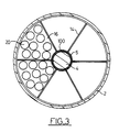
- this projectile comprises the casing (2) integral with the axial rod (4) which penetrates into the striped tube (5) thanks to the combination 100 as previously described.
- this tube (5) are fixed, for example, elements (14), for example, metallic, to establish compartments (16) inside which the submunitions (20) are positioned.
- the set of submunitions (20) is held in each compartment by holding means, for example, a belt (15) controlled, for example, by an explosive system not shown, which ensures that all of the tube submunitions (5); these holding means are generally unlocked when the assembly of submunitions (20) and tube (5) has reached a maximum speed which constitutes the initial speed of the submunitions (20) after ejection of the warhead (3) but they can be unlocked in a delayed manner and for each compartment.
- holding means for example, a belt (15) controlled, for example, by an explosive system not shown, which ensures that all of the tube submunitions (5); these holding means are generally unlocked when the assembly of submunitions (20) and tube (5) has reached a maximum speed which constitutes the initial speed of the submunitions (20) after ejection of the warhead (3) but they can be unlocked in a delayed manner and for each compartment.
- FIG. 4 which illustrates an alternative embodiment of the invention, a reverse architecture is produced.
- the rod (4) acting as a piston is this time made integral with the base (13).
- the tube (5) and the chamber (6) are then made integral with the warhead (3).
- the submunitions (20) are connected to the rear part, that is to say to the base (13 ) by any known means (30); Whichever variant is chosen, a roll speed is thus obtained when the submunitions are released, which gives the submunitions a transverse ejection speed.
- Axial inertias front part I1 1.13 m2 kg.
- rear part I2 1.97 m2 kg.
- This last speed is to be added to the initial roll speed of the vehicle, if it exists. If this speed is 10 turns / s and the submunitions are placed between 54 mm and 120 mm from the axis (xx ′) of the projectile, the ejection speeds perpendicular to this axis are between 9 and 20 ms ⁇ 1.
Landscapes
- Engineering & Computer Science (AREA)
- Chemical & Material Sciences (AREA)
- Combustion & Propulsion (AREA)
- General Engineering & Computer Science (AREA)
- Automotive Seat Belt Assembly (AREA)
- Portable Nailing Machines And Staplers (AREA)
Claims (6)
- Verfahren zum Auswerfen von Submunitionen aus einem diese tragenden Projektil (1), wobei das Projektil (1) aufweist:- einerseits einen Mantel (2), der in eine Spitze (3) mündet, die einen vorderen Teil bildet, wobei dieser vordere Teil durch Verriegelungsmittel (12) mit einem "Boden" genannten, hinteren Teil (13) verriegelt ist;- andererseits eine Stange (6), die sich im Inneren eines Rohrs (5) verschiebt, um unter der Wirkung einer pyrotechnischen Ladung als Kolben zu dienen, um den hinteren Teil von dem vorderen Teil zu trennen;
wobei das Verfahren dadurch gekennzeichnet ist, daß es darin besteht, nach dem Entriegeln der Verriegelungsmittel und dem Zünden der pyrotechnischen Ladung den vorderen Teil des Projektils bezüglich seines hinteren Teils drehen zu lassen, wobei die Submunitionen (20) durch Haltemittel (15) mit dem hinteren Teil fest verbunden sind; dies dank der Kombination von Zügen, die an einem der Teile des Projektils vorgesehen sind und mit einem Führungsband zusammenwirken, das selbst Züge aufweist und mit dem anderen Teil fest verbunden ist, um jeder der Submunitionen (20) eine Anfangsquergeschwindigkeit (v) zu verleihen, die es ermöglicht, eine optimale Streuung der Submunitionen (20) zu erhalten. - Projektil, das Submunitionen (20) trägt und dazu bestimmt ist, das Verfahren nach Anspruch 1 durchzuführen und aufweist:- einerseits einen Mantel (2), der in eine Spitze (3) mündet, die einen vorderen Teil bildet, wobei dieser Teil durch Verriegelungsmittel (12) mit einem "Boden" genannten, hinteren Teil (13) verriegelt ist;- andererseits eine Stange (6), die sich im Inneren eines Rohrs (5) verschiebt, um unter der Wirkung einer pyrotechnischen Ladung als Kolben zu dienen, um den hinteren Teil von dem vorderen Teil zu trennen, dadurch gekennzeichnet, daß die Submunitionen (20) durch Haltemittel (15) fest mit dem hinteren Teil verbunden sind, und daß sich der vordere Teil des Projektils bezüglich des hinteren Teils des Projektils dank einer Kombination von Zügen drehen kann, die an einem der Teile des Projektils vorgesehen sind und mit einem Führungsband zusammenwirken, das selbst Züge aufweist und mit dem anderen Teil des Projektils fest verbunden ist.
- Projektil nach Anspruch 2, dadurch gekennzeichnet, daß die Stange (4) fest mit der Spitze und das Rohr (5) fest mit dem Boden verbunden sind, wobei die Züge an dem Rohr (5) und die Zahneinschnitte oder das Führungsband an der Stange (4) vorgesehen sind.
- Projektil nach Anspruch 2, dadurch gekennzeichnet, daß das Rohr (5) fest mit der Spitze (3) und der Kolben fest mit dem Boden (13) verbunden ist, wobei die Züge an dem Rohr (5) und die Zahneinschnitte oder das Führungsband an der Stange (4) vorgesehen sind.
- Projektil nach Anspruch 2, dadurch gekennzeichnet, daß die Stange (4) mit Zügen versehen ist, wobei die Zahneinschnitte oder das Führungsband dann im inneren Teil des Rohrs (5) liegen, das die Rolle einer Kanonenmündung spielt.
- Projektil nach Anspruch 2, dadurch gekennzeichnet, daß die Haltemittel durch ein Band (15) gebildet sind, das die Befestigung der Einheit aus den Submunitionen (20) am hinteren Teil (13) des Projektils ermöglicht.
Applications Claiming Priority (2)
| Application Number | Priority Date | Filing Date | Title |
|---|---|---|---|
| FR8807767 | 1988-06-10 | ||
| FR8807767A FR2632721B1 (fr) | 1988-06-10 | 1988-06-10 | Procede d'ejection de sous-munitions et projectile mettant en oeuvre un tel procede |
Publications (2)
| Publication Number | Publication Date |
|---|---|
| EP0346214A1 EP0346214A1 (de) | 1989-12-13 |
| EP0346214B1 true EP0346214B1 (de) | 1993-08-11 |
Family
ID=9367163
Family Applications (1)
| Application Number | Title | Priority Date | Filing Date |
|---|---|---|---|
| EP89401561A Expired - Lifetime EP0346214B1 (de) | 1988-06-10 | 1989-06-06 | Verfahren und Vorrichtung zum Auswerfen von Submunition |
Country Status (4)
| Country | Link |
|---|---|
| US (1) | US5005483A (de) |
| EP (1) | EP0346214B1 (de) |
| DE (1) | DE68908285T2 (de) |
| FR (1) | FR2632721B1 (de) |
Families Citing this family (31)
| Publication number | Priority date | Publication date | Assignee | Title |
|---|---|---|---|---|
| DE4026813C1 (de) * | 1990-08-24 | 1996-09-26 | Rheinmetall Ind Gmbh | Flugkörper zur Bekämpfung eines Hubschraubers |
| FR2668255B1 (fr) * | 1990-10-19 | 1994-08-26 | Thomson Brandt Armements | Dispositif de solidarisation de grenades a l'interieur d'un projectile en rotation autour de son axe longitudinal. |
| IL121220A0 (en) * | 1996-07-25 | 1998-01-04 | Trw Inc | Countermeasure apparatus for deploying interceptor elements from a spin stabilized rocket |
| US6279482B1 (en) * | 1996-07-25 | 2001-08-28 | Trw Inc. | Countermeasure apparatus for deploying interceptor elements from a spin stabilized rocket |
| DE19749168A1 (de) * | 1997-11-07 | 1999-05-12 | Diehl Stiftung & Co | Gefechtskopf für eine Rakete |
| RU2137086C1 (ru) * | 1997-11-10 | 1999-09-10 | Государственное научно-производственное предприятие "Сплав" | Кассетная головная часть для противотанкового минирования местности |
| RU2138763C1 (ru) * | 1998-07-06 | 1999-09-27 | Государственное научно-производственное предприятие "Сплав" | Кассетная боевая часть реактивного снаряда |
| RU2150078C1 (ru) * | 1999-02-11 | 2000-05-27 | Государственный НИИМашиностроения | Кассетная боевая часть |
| RU2156428C1 (ru) * | 2000-01-19 | 2000-09-20 | Федеральное государственное унитарное предприятие Производственное объединение "АЛМАЗ" | Корпус кассетной боевой части реактивного снаряда |
| RU2166177C1 (ru) * | 2000-03-29 | 2001-04-27 | Государственное унитарное предприятие "Государственное научно-производственное предприятие "Сплав" | Кассетная головная часть |
| SE522934C2 (sv) * | 2000-07-03 | 2004-03-16 | Bofors Defence Ab | Sätt och anordning för spridning av substridsdelar |
| US6505561B1 (en) * | 2001-04-25 | 2003-01-14 | Raytheon Company | Method and apparatus for inducing rotation of a dispensed payload from non-spin projectiles |
| US6672220B2 (en) * | 2001-05-11 | 2004-01-06 | Lockheed Martin Corporation | Apparatus and method for dispersing munitions from a projectile |
| SE523695C2 (sv) * | 2001-06-12 | 2004-05-11 | Saab Ab | Ammunitionsanordning, såsom granat eller liknande, lämpad för hålslagning i väggar eller likartade konstruktioner |
| US6910423B2 (en) * | 2001-08-23 | 2005-06-28 | Raytheon Company | Kinetic energy rod warhead with lower deployment angles |
| US6640723B2 (en) * | 2002-03-25 | 2003-11-04 | The United States Of America As Represented By The Secretary Of The Navy | Mission responsive ordnance |
| RU2225586C1 (ru) * | 2002-07-09 | 2004-03-10 | Федеральное Государственное унитарное предприятие "Государственное научно-производственное предприятие "Сплав" | Кассетная боевая часть |
| FR2860580B1 (fr) * | 2003-10-03 | 2005-12-16 | Giat Ind Sa | Munition anti bunker |
| US7261039B1 (en) * | 2006-04-07 | 2007-08-28 | The United States Of America As Represented By The Secretary Of The Army | Artillery Rocket Kinetic Energy Rod Warhead |
| RU2299396C1 (ru) * | 2006-04-13 | 2007-05-20 | Федеральное государственное унитарное предприятие "Производственное объединение "Алмаз" | Кассетная головная часть вращающейся ракеты |
| DE102007048073A1 (de) * | 2007-10-05 | 2009-04-09 | Rheinmetall Waffe Munition Gmbh | Verfahren zum Verbringen von Sonarbojen in ein Zielgebiet und Flugkörper zur Durchführung dieses Verfahrens |
| RU2435130C1 (ru) * | 2010-06-22 | 2011-11-27 | Федеральное Государственное унитарное предприятие "Государственное научно-производственное предприятие "Сплав" | Реактивный снаряд с кассетной головной частью |
| US8403267B2 (en) * | 2010-11-29 | 2013-03-26 | Raytheon Company | Ejection system and a method for ejecting a payload from a payload delivery vehicle |
| JP2016531265A (ja) * | 2013-08-20 | 2016-10-06 | ビ−エイイ− システムズ パブリック リミテッド カンパニ−BAE SYSTEMS plc | 煙ペイロード装置 |
| RU2645045C1 (ru) * | 2016-12-21 | 2018-02-15 | Акционерное общество "Научно-производственное объединение "СПЛАВ" | Корпус кассетной головной части реактивного снаряда |
| SG11202007355TA (en) | 2018-02-05 | 2020-08-28 | Advanced Mat Engineering Pte Ltd | System for countering an unmanned aerial vehicle (uav) |
| RU2713683C1 (ru) * | 2019-03-19 | 2020-02-06 | Федеральное государственное унитарное предприятие "Центральный научно-исследовательский институт химии и механики" (ФГУП "ЦНИИХМ") | Способ поражения площадной цели групповым действием суббоеприпасов кассетных боеприпасов |
| CN112414231B (zh) * | 2020-11-10 | 2021-08-24 | 北京理工大学 | 一种基于分布式战斗部的多点起爆安全系统及其控制方法 |
| DE102022134714A1 (de) * | 2022-12-23 | 2024-07-04 | Globe UAV GmbH | Vorrichtung zur Abwehr von einem Luftfahrzeug |
| US20260118102A1 (en) * | 2023-02-12 | 2026-04-30 | Richard M Terasaki | Multiple Projectile Impeller Ejection Warhead For ICBM Interception |
| US12253345B2 (en) * | 2023-05-29 | 2025-03-18 | John R. Tiffany | Accurate, low recoil shotshell |
Family Cites Families (10)
| Publication number | Priority date | Publication date | Assignee | Title |
|---|---|---|---|---|
| US1488182A (en) * | 1921-11-17 | 1924-03-25 | Gordon T Whelton | Ordnance projectile |
| US2972946A (en) * | 1950-07-07 | 1961-02-28 | Thomas C Poulter | Bomb cluster |
| US3064575A (en) * | 1959-04-17 | 1962-11-20 | Schermuly Pistol Rocket App | Dischargers for pyrotechnic devices |
| GB924690A (en) * | 1960-11-03 | 1963-05-01 | Schermuly Pistol Rocket App | Improved pyrotechnic device |
| GB1085045A (en) * | 1966-02-10 | 1967-09-27 | Forsvarets Fabriksverk | A projectile or aerial bomb |
| GB1434034A (en) * | 1972-07-11 | 1976-04-28 | Bender Ltd F | Method and equipment for forming a single cloud of radar reflecting chaff within the atmosphere |
| DE3327043A1 (de) * | 1983-07-27 | 1985-02-07 | Technisch-Mathematische Studiengesellschaft mbH, 5300 Bonn | Vorrichtung zum ausstreuen elektromagnetischen scheinzielmaterials, insbesondere aus einer rakete |
| US4676167A (en) * | 1986-01-31 | 1987-06-30 | Goodyear Aerospace Corporation | Spin dispensing method and apparatus |
| US4682546A (en) * | 1986-10-02 | 1987-07-28 | Chovich Milija M | Projectile |
| FR2606135B1 (fr) * | 1986-10-31 | 1990-07-27 | Thomson Brandt Armements | Projectile comportant des sous-projectiles a largage directionnel controle |
-
1988
- 1988-06-10 FR FR8807767A patent/FR2632721B1/fr not_active Expired - Fee Related
-
1989
- 1989-06-06 DE DE89401561T patent/DE68908285T2/de not_active Expired - Fee Related
- 1989-06-06 EP EP89401561A patent/EP0346214B1/de not_active Expired - Lifetime
- 1989-06-07 US US07/362,661 patent/US5005483A/en not_active Expired - Lifetime
Also Published As
| Publication number | Publication date |
|---|---|
| FR2632721B1 (fr) | 1993-05-07 |
| FR2632721A1 (fr) | 1989-12-15 |
| DE68908285T2 (de) | 1994-02-17 |
| DE68908285D1 (de) | 1993-09-16 |
| EP0346214A1 (de) | 1989-12-13 |
| US5005483A (en) | 1991-04-09 |
Similar Documents
| Publication | Publication Date | Title |
|---|---|---|
| EP0346214A1 (de) | Verfahren und Vorrichtung zum Auswerfen von Submunition | |
| EP0905473B1 (de) | Grosskalibriges und weitreichendes Artilleriegeschoss | |
| FR2526149A1 (fr) | Systeme d'arme et munition de survol | |
| FR2606135A1 (fr) | Projectile comportant des sous-projectiles a largage directionnel controle | |
| WO2014080136A1 (fr) | Projectile gyrostabilise projetant une charge utile | |
| EP1045221B1 (de) | Bremsvorrichtung für die Flugbahngeschwindigkeit eines Geschosses | |
| EP0143720B1 (de) | Munition für Jagdgewehr | |
| FR2572512A1 (fr) | Dispositif, adaptable sur engins ou munitions, tels que projectiles d'artillerie, destine a reduire leur trainee de culot | |
| EP0053855B1 (de) | Rotor für eine Zentrifugalschleuderwaffe | |
| EP0130893B1 (de) | Trägergeschoss für Streumunition | |
| EP0457657B1 (de) | Durchdringendes Geschoss | |
| EP0918205B1 (de) | Projektil mit radialer Wirkrichtung | |
| FR3011919A1 (fr) | Dispositif de freinage en rotation d'une enveloppe d'une charge utile, et projectile gyrostabilise equipe d'un tel dispositif | |
| EP2578987B1 (de) | Drallstabilisiertes Geschoss | |
| FR2552871A1 (fr) | Projectile antichar agissant en vitesse defilante | |
| EP0401114B1 (de) | Vorrichtung zum Halten eines Geschosses in bezug auf das Gehäuse einer teleskopartigen Munition | |
| EP0268535A1 (de) | Drehbarer Führungsring für Geschosse jeden Kalibers | |
| EP0281462B1 (de) | Munition, insbesondere für Artillerie, bestehend aus einem Geschoss und einer Hülse | |
| FR2769083A1 (fr) | Procede de guidage d'un missile et missile pour la mise en oeuvre du procede | |
| FR2669722A1 (fr) | Systeme d'arme agissant par attaque plongeante sur l'objectif. | |
| WO1991002211A1 (fr) | Perfectionnements apportes aux munitions destinees a etre tirees par une arme a canon lisse | |
| EP4088082B1 (de) | Teleskopische munition mit einem durch eine ausfahrbare leitvorrichtung stabilisierten unterkalibrigen geschoss | |
| EP0027418B1 (de) | Vorrichtung zum Abfeuern eines Geschosses ohne rückwärtige Gasabfuhr und ohne Rückstoss mittels eines beidseitig offenen Abschussrohres | |
| FR2507765A1 (fr) | Procede et dispositif de tir d'une munition fleche a l'aide d'un tube raye | |
| EP0250329B2 (de) | Munitionstreibladung, insbesondere für Pfeilgeschosse grossen Kalibers |
Legal Events
| Date | Code | Title | Description |
|---|---|---|---|
| PUAI | Public reference made under article 153(3) epc to a published international application that has entered the european phase |
Free format text: ORIGINAL CODE: 0009012 |
|
| AK | Designated contracting states |
Kind code of ref document: A1 Designated state(s): CH DE FR GB IT LI SE |
|
| 17P | Request for examination filed |
Effective date: 19900518 |
|
| 17Q | First examination report despatched |
Effective date: 19920123 |
|
| GRAA | (expected) grant |
Free format text: ORIGINAL CODE: 0009210 |
|
| AK | Designated contracting states |
Kind code of ref document: B1 Designated state(s): CH DE FR GB IT LI SE |
|
| ITF | It: translation for a ep patent filed | ||
| REF | Corresponds to: |
Ref document number: 68908285 Country of ref document: DE Date of ref document: 19930916 |
|
| GBT | Gb: translation of ep patent filed (gb section 77(6)(a)/1977) |
Effective date: 19930915 |
|
| PLBE | No opposition filed within time limit |
Free format text: ORIGINAL CODE: 0009261 |
|
| STAA | Information on the status of an ep patent application or granted ep patent |
Free format text: STATUS: NO OPPOSITION FILED WITHIN TIME LIMIT |
|
| 26N | No opposition filed | ||
| EAL | Se: european patent in force in sweden |
Ref document number: 89401561.9 |
|
| PGFP | Annual fee paid to national office [announced via postgrant information from national office to epo] |
Ref country code: CH Payment date: 19960513 Year of fee payment: 8 |
|
| PG25 | Lapsed in a contracting state [announced via postgrant information from national office to epo] |
Ref country code: LI Free format text: LAPSE BECAUSE OF NON-PAYMENT OF DUE FEES Effective date: 19970630 Ref country code: CH Free format text: LAPSE BECAUSE OF NON-PAYMENT OF DUE FEES Effective date: 19970630 |
|
| REG | Reference to a national code |
Ref country code: CH Ref legal event code: PL |
|
| REG | Reference to a national code |
Ref country code: GB Ref legal event code: IF02 |
|
| PGFP | Annual fee paid to national office [announced via postgrant information from national office to epo] |
Ref country code: SE Payment date: 20020522 Year of fee payment: 14 Ref country code: GB Payment date: 20020522 Year of fee payment: 14 |
|
| PGFP | Annual fee paid to national office [announced via postgrant information from national office to epo] |
Ref country code: FR Payment date: 20020621 Year of fee payment: 14 |
|
| PG25 | Lapsed in a contracting state [announced via postgrant information from national office to epo] |
Ref country code: GB Free format text: LAPSE BECAUSE OF NON-PAYMENT OF DUE FEES Effective date: 20030606 |
|
| PG25 | Lapsed in a contracting state [announced via postgrant information from national office to epo] |
Ref country code: SE Free format text: LAPSE BECAUSE OF NON-PAYMENT OF DUE FEES Effective date: 20030607 |
|
| PGFP | Annual fee paid to national office [announced via postgrant information from national office to epo] |
Ref country code: DE Payment date: 20030618 Year of fee payment: 15 |
|
| GBPC | Gb: european patent ceased through non-payment of renewal fee |
Effective date: 20030606 |
|
| EUG | Se: european patent has lapsed | ||
| PG25 | Lapsed in a contracting state [announced via postgrant information from national office to epo] |
Ref country code: FR Free format text: LAPSE BECAUSE OF NON-PAYMENT OF DUE FEES Effective date: 20040227 |
|
| REG | Reference to a national code |
Ref country code: FR Ref legal event code: ST |
|
| PG25 | Lapsed in a contracting state [announced via postgrant information from national office to epo] |
Ref country code: DE Free format text: LAPSE BECAUSE OF NON-PAYMENT OF DUE FEES Effective date: 20050101 |
|
| PG25 | Lapsed in a contracting state [announced via postgrant information from national office to epo] |
Ref country code: IT Free format text: LAPSE BECAUSE OF NON-PAYMENT OF DUE FEES Effective date: 20050606 |