EP3788249B1 - Projektil mit staustrahltriebwerk - Google Patents
Projektil mit staustrahltriebwerk Download PDFInfo
- Publication number
- EP3788249B1 EP3788249B1 EP19728126.4A EP19728126A EP3788249B1 EP 3788249 B1 EP3788249 B1 EP 3788249B1 EP 19728126 A EP19728126 A EP 19728126A EP 3788249 B1 EP3788249 B1 EP 3788249B1
- Authority
- EP
- European Patent Office
- Prior art keywords
- control module
- projectile
- air inlet
- propelled
- trajectory
- Prior art date
- Legal status (The legal status is an assumption and is not a legal conclusion. Google has not performed a legal analysis and makes no representation as to the accuracy of the status listed.)
- Active
Links
Images

Classifications
-
- F—MECHANICAL ENGINEERING; LIGHTING; HEATING; WEAPONS; BLASTING
- F42—AMMUNITION; BLASTING
- F42B—EXPLOSIVE CHARGES, e.g. FOR BLASTING, FIREWORKS, AMMUNITION
- F42B10/00—Means for influencing, e.g. improving, the aerodynamic properties of projectiles or missiles; Arrangements on projectiles or missiles for stabilising, steering, range-reducing, range-increasing or fall-retarding
- F42B10/32—Range-reducing or range-increasing arrangements; Fall-retarding means
- F42B10/38—Range-increasing arrangements
- F42B10/40—Range-increasing arrangements with combustion of a slow-burning charge, e.g. fumers, base-bleed projectiles
-
- F—MECHANICAL ENGINEERING; LIGHTING; HEATING; WEAPONS; BLASTING
- F02—COMBUSTION ENGINES; HOT-GAS OR COMBUSTION-PRODUCT ENGINE PLANTS
- F02K—JET-PROPULSION PLANTS
- F02K7/00—Plants in which the working fluid is used in a jet only, i.e. the plants not having a turbine or other engine driving a compressor or a ducted fan; Control thereof
- F02K7/10—Plants in which the working fluid is used in a jet only, i.e. the plants not having a turbine or other engine driving a compressor or a ducted fan; Control thereof characterised by having ram-action compression, i.e. aero-thermo-dynamic-ducts or ram-jet engines
- F02K7/18—Composite ram-jet/rocket engines
-
- F—MECHANICAL ENGINEERING; LIGHTING; HEATING; WEAPONS; BLASTING
- F02—COMBUSTION ENGINES; HOT-GAS OR COMBUSTION-PRODUCT ENGINE PLANTS
- F02K—JET-PROPULSION PLANTS
- F02K9/00—Rocket-engine plants, i.e. plants carrying both fuel and oxidant therefor; Control thereof
- F02K9/08—Rocket-engine plants, i.e. plants carrying both fuel and oxidant therefor; Control thereof using solid propellants
-
- F—MECHANICAL ENGINEERING; LIGHTING; HEATING; WEAPONS; BLASTING
- F02—COMBUSTION ENGINES; HOT-GAS OR COMBUSTION-PRODUCT ENGINE PLANTS
- F02K—JET-PROPULSION PLANTS
- F02K9/00—Rocket-engine plants, i.e. plants carrying both fuel and oxidant therefor; Control thereof
- F02K9/74—Rocket-engine plants, i.e. plants carrying both fuel and oxidant therefor; Control thereof combined with another jet-propulsion plant
- F02K9/78—Rocket-engine plants, i.e. plants carrying both fuel and oxidant therefor; Control thereof combined with another jet-propulsion plant with an air-breathing jet-propulsion plant
-
- F—MECHANICAL ENGINEERING; LIGHTING; HEATING; WEAPONS; BLASTING
- F42—AMMUNITION; BLASTING
- F42B—EXPLOSIVE CHARGES, e.g. FOR BLASTING, FIREWORKS, AMMUNITION
- F42B10/00—Means for influencing, e.g. improving, the aerodynamic properties of projectiles or missiles; Arrangements on projectiles or missiles for stabilising, steering, range-reducing, range-increasing or fall-retarding
- F42B10/60—Steering arrangements
- F42B10/62—Steering by movement of flight surfaces
- F42B10/64—Steering by movement of flight surfaces of fins
Definitions
- the technical field of the invention is that of propelled projectiles and in particular propelled artillery projectiles.
- patents FR2479905 And FR2522134 describe a shell having at its warhead a small powder propellant which is ignited during the initial phase of the trajectory to prolong to some extent the impulse resulting from the cannon fire.
- the propelled projectiles have a high ballistic dispersion which also increases significantly with range.
- Known trajectory correction means include control surfaces arranged at the projectile nose (commonly referred to as “Canards Actuating System” or CAS). These means are generally associated with shells or projectiles that are not propelled by ramjet, such as those described by the patents EP1297292 , FR2768809 , EP2767794 , Or FR3054030 .
- trajectory correction control surfaces is not very compatible with the geometry of a ramjet projectile and the aerodynamics of the axial air intake, which must not present any obstacle or aerodynamic singularity to ensure the initiation of combustion and its nominal operation in the cruise phase.
- THE patent DE3321945 describes a projectile fired from a gun and which has a payload mounted sliding relative to a propellant. At the exit of the gun barrel the acceleration decreases and the payload is pushed out of the propellant tube by the pressure of the firing gases. The movement of the payload is sufficient to open the passage of air into an annular chamber, which ignites the ramjet.
- This projectile has no means of correcting its trajectory. Furthermore, there is no question of closing the air inlet orifice on the trajectory to cut the ramjet.
- the aim of the invention is to propose a ramjet-propelled projectile which is nevertheless controllable in order to give it precision in reaching its target regardless of the range, and therefore the flight time.
- the invention is more particularly described in its application to an artillery shell.
- the invention relates to a ramjet-propelled projectile, a projectile comprising an external body and a deployable tail, a projectile comprising inside the body a chamber in which is housed an ablatable annular semi-propellant block as well as an envelope containing a military charge, the external body comprising an air inlet to allow air to enter the chamber, the body also comprising a rear opening on which a nozzle is positioned, a projectile characterized in that it comprises a pilot module arranged axially and which extends through the air inlet, the pilot module being able to be moved axially by a motor means, during the flight of the projectile and at a defined instant on the trajectory, called the extinction instant, from a rear position in which it does not block the air inlet, to a forward position in which it blocks the air inlet, the pilot module containing at least two canard control surfaces which are deployable outside the projectile after blocking the air inlet.
- the control module may contain a calculation means incorporating control algorithms, the calculation means ensuring control of the movement of the control module at the instant of extinction.
- the propelled projectile will constitute an artillery projectile intended to be fired by a cannon, a projectile whose external body will carry a sliding belt.
- control module may be in its forward position before firing, the control module moving back by inertia during the cannon firing so as to occupy its rear position in which it will rest against the military charge envelope.
- the projectile may include a locking means ensuring the immobilization of the control module in the rear position.
- the motor means may comprise a means of storing elastic potential energy, this means being activated by the recoil of the control module from its front part to its rear part, the locking means being released at the extinction instant defined on the trajectory.
- control module is in its front position before firing, the control module being able to be moved by the motor means, after firing and at a time, called ignition, defined on the trajectory, so as to come and occupy its rear position.
- the motor unit will thus be able to move, progressively or incrementally, at different successive moments defined on the trajectory, the control module from its front position to its rear position.
- the motor means may move the control module to its rear position at the end of the controlled phase so as to clear the air intake and accelerate thus the projectile during a terminal phase of its trajectory.
- the control module may include a rear skirt that can slide on an external wall of the casing when the control module is moved so as to improve the continuity of the air flow during operation of the ramjet and for all longitudinal positions of the control module.
- the projectile will have a rear base closing the nozzle during firing, a base ensuring the maintenance of the rear tail and which is ejected at the exit of the barrel.
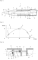
- a ramjet-propelled projectile 1 according to one embodiment of the invention comprises a body 2 and a deployable tail 3 which is kept folded, during storage phases and during the ballistic journey in the tube, by a rear thrust base 4.
- the body 2 carries a slip belt 5 which ensures gas-tightness inside the barrel of the weapon and which also makes it possible to limit by sliding the rotation speed which can be communicated to the projectile by the grooves of the barrel of the weapon (the sliding rate is of the order of 90% minimum).
- an artillery barrel is generally grooved to ensure the rotation of the projectiles.
- Base 4 will be ejected at the exit of the weapon tube and tail 3 will deploy to ensure the aerostabilization of the projectile on trajectory.
- Aerostabilization is necessary due to the architecture of the projectile (low longitudinal moment of inertia which does not allow gyroscopic stability criteria to be met) and the reduction in speed of roll on trajectory when the projectile is in the piloted phase due to the high roll damping coefficient (Clp) of the tail. Aerostabilization is finally necessary to make subsequent piloting possible via control surfaces.
- the control of the control surface deflections to the roll position of the projectile is in fact limited in roll speed by the bandwidth of the computer and the actuators.
- the rotation speed of the shell leaving the tube is of the order of some 10 revolutions per second.
- slip belts are well known to those skilled in the art in the field of artillery projectiles. The following may be consulted: patents WO03001141 , EP1693646 And EP1386120 which describe such belts.
- Deploying tailplanes are also well known to those skilled in the art (see the patent EP0905473 ).
- the projectile 1 has inside the body 2 a chamber 6 in which is housed an annular block 7 of a fuel consisting of an ablatable semi-propellant.
- Room 6 also receives an envelope 8 which contains a military charge 9, for example an explosive charge.
- a military charge 9 for example an explosive charge.
- the casing 8 is connected to the body 2 by radial connecting arms 10 which are profiled and which are regularly distributed angularly. There are here three groups of three arms 10. The three arms of each group are angularly spaced from each other by 120°.
- the body 2 has an annular air inlet 11 which is closed during storage and firing by a module steering 12 (this advanced position - figure 1 - is its reference position).
- the air inlet 11 is intended to allow air to enter the chamber 6 when the projectile is in the propelled phase.
- the body 2 also has a rear opening 13 on which a nozzle 14 is positioned.
- the base 4 whose primary function is to accelerate the projectile by transmitting the thrust of the firing gases to it, also makes it possible to close the nozzle 14 during firing, thus isolating the fuel block 7 of the ramjet from the hot gases of the propellant powder charge which push the projectile out of the weapon barrel.
- the piloting module 12 contains at least two canard control surfaces 15 (arranged in the same plane and materializing a piloting plane) as well as their deployment mechanism (not shown).
- Such deployable control surface devices are well known and described in particular by the patents FR2949848 , FR2846080 , FR2864613 And FR2891618 .
- canard rudders and their deployment and orientation mechanism into a piloting module with a diameter of around 60 to 90 millimeters which is incorporated into a 155 millimeter caliber projectile.
- the control module 12 contains sensors (inertial, magnetic, etc.) and also a calculation means 16 incorporating control algorithms allowing the control of the steering of the control surfaces to direct the projectile towards a target whose coordinates will have been entered into the calculation means 16 before firing by a programming means not shown, for example by a connection interface or by contactless programming through an inductive loop connected to the calculation means 16.
- the control module 12 is therefore a subassembly of the projectile which incorporates means for correcting the trajectory of the projectile (deployable control surfaces 15).
- This control module may also contain the means associated with the control surfaces and enabling their control (computing means 16).
- the computing means could be positioned elsewhere on the projectile, for example in the envelope 8, but it is more advantageous to house them in the control module 12 which is mobile relative to the envelope 8.
- the control module 12 is arranged axially and it extends through the air inlet 11 and has in particular a tip 12a extending in front of the air inlet 11.
- the control module 12 can be moved axially along the axis 26 of the projectile by a motor means, during the flight of the projectile and at a desired instant on the trajectory (i.e. a defined instant, called the extinction instant).
- the movement will be from a rear position, in which the control module 12 is supported against the casing 8 of the warhead 9, to a front position in which it closes the air inlet 11, thus stopping the combustion of the fuel block 7 and stopping the ramjet.
- This device therefore makes it possible to control the operating time of the ramjet, which is one of the advantages of the invention.
- the control module 12 comprises a peripheral shoulder 12b which comes to bear against an annular stop surface carried by the body 2 when this module 12 is in the closed position shown in figure 1 .
- control module 12 is defined so as to promote the flow of air and its entry inside the chamber 6 when the control module 12 is in its rear position and the air inlet 11 is clear.
- This profile is well known to those skilled in the art, and it is conventionally used in tests in blower to optimize this profile which ensures the important function of compressing and heating the flow upstream of the combustion chamber 6.
- the calculation means 16 makes it possible to control the movement of the control module 12 at a desired instant on the trajectory (i.e. at a defined instant) and it also makes it possible to control the deployment of the fins 15 as will be described later.
- the term “desired instant on the trajectory” means an instant that is predefined by the design of the projectile or that has been defined and programmed before firing. This instant is managed by the calculation means 16 of the control module 12.
- the extinction instant is thus the instant at which the control means 12 is moved from its rear position to its front position in which it closes the air inlet 11.
- the movement is done by sliding the control module 12 for example on one or more columns 17 secured to the casing 8 and which penetrate into the control module 12 when the latter moves back.
- a single column or central axis may be used alternatively.
- the motor means may be constituted by a small motor incorporated in the control module 12 and meshing for example on a rack carried by one of the columns 17.
- At least one of the columns 17 may be equipped with a traction spring 18 which will be fixed on the one hand to a collar 19 of the column 17 and on the other hand to the wall of the control module 12.
- This traction spring 18 will constitute the motor means which is here a means of storing elastic potential energy.
- FIG. 3a shows the assembly before firing.
- the spring 18 is at rest, in the unstretched state.
- the column 17 passes through a transverse wall 20 secured to the module 12 and which ensures its guidance.
- the wall 20 carries an electromagnetic lock 21 (shown very schematically) which is intended to engage in a groove 22 of the column 17.
- This electromagnetic lock 21 constitutes a locking means which will make it possible to ensure the immobilization of the control module 12 in the rear position.
- control module 12 moves back due to its inertia.
- a shearable retaining pin (not shown) may be provided between the body 2 of the projectile and the control module 12 to secure the assembly in the storage position. This recoil movement has the effect of stretching the traction spring 18 (storage of elastic potential energy).
- the control module 12 comes to bear against the casing 8 of the warhead 9.
- the groove 22 is positioned opposite the electromagnetic lock 21 which ensures the locking of the column 17.
- the electromagnetic lock 21 will comprise a spring pushing a locking finger into the groove 22. No energy is therefore necessary for locking.
- the calculation means 16 will send a pulse to the electromagnetic lock 21 via a control wire 23, causing the release of the latter.
- the spring 18 then ensures the return of the module 12 to its front position.
- the column 17 may be tubular to allow a wire 24 to pass through to control the firing of the military charge 9 by means of a detonator 25.
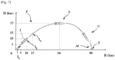
- FIG. 2 is a curve showing the different phases of flight of the projectile 1 according to the invention.
- the abscissa axis corresponds to the range R of the projectile and the ordinate axis to the altitude H of the projectile.
- the projectile goes through several phases.
- the thrust base 4 When firing the weapon, the thrust base 4 is in place, it keeps the tail unit 3 in the folded position and protects it, as well as the fuel block 7 ( figure 1 ).
- the acceleration of the shot has the effect of moving the control module 12 backwards, which locks against the casing 8 ( Figures 3b and 4a ).
- the base 4 is ejected (for example by an ejection charge as described by the patent FR2768809 or by an effort generated by a differential of pressure, or even by the effect of the residual rotation communicated by the tube.
- the ejection of the base 4 at the tube outlet allows the deployment of the fins 3a of the empennage 3 ( Figure 4a ) which aerostabilizes the projectile 1 throughout the trajectory by ensuring a residual and maintained roll speed of a few revolutions per second.
- This roll speed is obtained by means of an angular setting of the fins 3a relative to the axis 26 of the projectile or by a bevel made on the leading edge or on the trailing edge of each fin 3a.
- This residual rotation is necessary to pilot the projectile 1 over 360° and essential in the case of piloting by a single plane of control surfaces 15.
- the exit from the weapon tube is at a minimum speed of around 700 m/s, or around Mach 2, which corresponds, from the artillery point of view, to a choice of propellant charges ensuring a shot in "zone 4".
- a minimum speed of around 700 m/s, or around Mach 2 which corresponds, from the artillery point of view, to a choice of propellant charges ensuring a shot in "zone 4".
- the only limit of this type of propellant is the speed which is compatible with subsonic combustion inside the projectile, or a projectile speed of around Mach 5 (1700 m/s).
- Such a speed allows the priming of the ramjet formed by the general architecture of the projectile 1, once the pilot module 12 is positioned at the rear and the annular air inlet 11 is released.
- This ignition speed is optimal for the ignition and operation of the ramjet.
- the air flow entering the chamber 6 through the air inlet 11 is compressed, it heats up and spontaneously initiates the annular fuel block 7 and is accelerated in the nozzle 14, then evacuated.
- the fuel block 7 which is a semi-propellant lines the walls of the combustion chamber 6 and reacts spontaneously (self-ignition) with the flow from the annular air inlet 11. This air was compressed and heated following its slowing down by the profile of the air inlet 11 which acts as a static compressor and leads to the priming of the ramjet.
- the combustion of the semi-propellant produces hot gases ejected into the nozzle 14. All of the gases are converted into effective thrust and greatly accelerate the projectile 1.
- the speed obtained is between Mach 2 and Mach 5 (from 700m/s to 1700m/s) and a maximum altitude of the order of 25,000 m can be obtained in about a minute.
- the duration of the propelled phase can vary depending on the architecture of the ramjet (section of the air inlet 11, fuel mass, ejected mass flow rate, etc.) and the firing conditions and can range from a few seconds to a few tens of seconds (1 minute maximum, the limit being set by the altitude).
- the calculation means 16 controls the release of the motor means which causes the return of the control module 12 to its front position ( figure 4c ) in which it closes the annular air inlet 11.
- the calculation means 16 also causes the deployment of the canard control surfaces 15, after closing the air inlet 11.
- the canard control surface deployment mechanism is a classic mechanism that does not need to be described in detail.
- the deployment time (or extinction time) is programmed before firing and depends on the conditions of the firing considered. It is clear that, whatever the time at which the forward movement of the control module 12 is triggered, the closing of the annular air inlet 11 will cause the fuel block 7 to be extinguished due to lack of oxygen and the propulsion to stop.
- This zone corresponds to operating times between a few seconds and one minute (maximum). Propulsion efficiency is optimal at the start of the trajectory and in all cases before apogee A, which corresponds to maximum ranges for the propelled phase P of between 5 and 50 km.
- the calculation means 16 will control the piloting of the projectile in the direction of the target T whose coordinates were entered into memory before firing.
- the calculation means 16 is coupled to a means of positioning the projectile which may include a GPS and/or Galileo type receiver and/or an inertial unit.
- the deployed control surfaces are pivoted by one or more motors that are controlled by the calculation module 16.
- the control module 12 may also be equipped with infrared target sensors (not shown) located at the level of the module 12's warhead, sensors used for the final phase of the attack and allowing metric precision to be obtained.
- the precision can be metric or decametric depending on the guidance techniques implemented and the on-board sensors, and it is independent of the flight time, therefore of the range and of the weather conditions.
- the whole point of the invention is to provide these operational advantages using conventional artillery and existing firing charges for artillery systems.
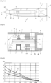
- FIG. 5 schematically shows another embodiment of a motor means.
- the motor means is constituted by an electric motor 27 which is equipped with a toothed wheel 28. The latter meshes with a tapped nut 29 which is engaged on a central axis 30 carrying a thread 31.
- the electric motor 27 is secured to the control module 12 by a flange 33. It is connected to the calculation means 16 by a wired connection 34. Its operation is controlled by the means of calculation 16 which will incorporate algorithms ensuring the rotation of the motor 27 in one direction or the other depending on the firing timing (therefore the location of the projectile 1 on its trajectory).
- the central axis 30 is integral with the casing 8 and is coaxial with the axis 26 of the projectile 1.
- the central axis 30 passes through a bottom wall 12c of the control module 12 through a hole 12d which has a diameter greater than that of the axis 30 and does not hinder the rotation of the central axis 30.
- Three columns 17, regularly distributed angularly around the axis 26 are integral with the casing 8 and slidably adjusted in holes in the bottom wall 12c of the control module 12. These columns 17 ensure the guidance of the translational movement of the control module 12 relative to the casing 8 while preventing the relative rotation of the module 12 relative to the casing 8.
- the nut 29 is also immobilized in translation relative to the control module 12 by means of two walls 35 secured to the control module 12.
- the walls 35 may have surfaces covered with an anti-friction coating to facilitate the rotation of the nut 29. Depending on the necessary travel, they may possibly be drilled so as not to hinder the passage of the column 17.
- the central axis 30 being immobile in rotation and in translation relative to the casing 8, the rotation of the motor 27 will cause the rotation of the nut 29 which, being integral in translation with the control module 12, will cause the axial displacement of the control module 12 along the central axis 30.
- control module 12 It is thus easy to control the longitudinal position of the control module 12 and, unlike the embodiment described above, it becomes possible to move the control module 12 axially in a manner uncorrelated with the firing of the projectile.
- control module 12 comprises a rear skirt 36 which slides on an external wall 8b of the casing 8.
- Such an arrangement makes it possible to improve the continuity of the air flow during operation of the ramjet and for all longitudinal positions of the control module 12.
- the ignition time at which the recoil of the control module 12 will be commanded after the shot, thus causing the ignition of the ramjet.
- Such an arrangement proves to be interesting from an operational point of view to improve the discretion of the shot by avoiding the ignition flashes of the semi-propellant block 7. It also makes it possible to optimize the trajectory profile of the projectile 1. This embodiment also makes it possible to avoid exceeding Mach 5 during a shot at high initial speed.
- the calculation means 16 will thus be able to control, at the end of a first time interval (at the ignition time) after the exit of the weapon barrel (of the order of a few tenths of a second), the recoil of the control module 12 to open the air inlet 11 of a minimum section allowing the ramjet to be ignited.
- the calculation means 16 will cause the control module 12 to move back again to open the air inlet 11 a little more and thus optimize the operation of the ramjet by increasing the air flow for an altitude at which the air is less dense.
- the calculation means 16 can thus move, progressively or incrementally, at different times on the trajectory, the control module 12 from its front position (air inlet 11 closed) to its rear position (maximum opening of the air inlet 11).
- curve S 1 corresponds to an air inlet section of 3000 mm 2
- curve S 2 corresponds to an air inlet section of 4000 mm 2
- curve S 3 corresponds to an air inlet section of 5000 mm 2 .
- the times between each movement are of the order of 4 to 5 seconds.
- the increase in the section of the air inlet 11 can also be controlled continuously.
- control module 12 After firing, and at a first instant I 1 or ignition instant (here approximately 5 km from the weapon), the control module 12 is moved back to open the air inlet 11 and ignite the ramjet.
- the pilot module 12 is moved a little further back to open the air intake 11 more, which improves the operation of the ramjet at a higher altitude (here 10 km).
- the pilot module 12 is moved even further back to open the air intake 11 to its maximum opening, which improves the operation of the ramjet at an even higher altitude (here 15 km).
- the electric motor 27 returns the pilot module 12 to its forward position in which it closes the air inlet 11 which extinguishes the ramjet.
- the canard control surfaces 15 are deployed and the piloted phase G begins.
- control surfaces 15 may, during this movement, be embedded on the body 2 around the air inlet 11, which no longer presents any disadvantages, the guidance having become unnecessary.
- the control surfaces may alternately fold forward in the module according to the design of their kinematics.
- canard rudders 15 comprising a pivot axis positioning the rudder wing at a radial distance from the pilot module 12 which thus allows the pilot module 12 to move backwards, with the rudders deployed, with minimal mechanical disturbances or interference.
- This final acceleration of projectile 1 lasting about 2 seconds is not essential but it increases the kinetic energy of projectile 1 at the end of its trajectory and also increases the stealth of the attack.
- the flight of the projectile returns to supersonic speed and the speed on impact with the target is of the order of Mach 2.
Landscapes
- Engineering & Computer Science (AREA)
- Chemical & Material Sciences (AREA)
- Combustion & Propulsion (AREA)
- General Engineering & Computer Science (AREA)
- Mechanical Engineering (AREA)
- Physics & Mathematics (AREA)
- Fluid Mechanics (AREA)
- Toys (AREA)
- Aiming, Guidance, Guns With A Light Source, Armor, Camouflage, And Targets (AREA)
Claims (11)
- - Projektil, angetrieben durch Staustrahltriebwerk, das Projektil (1) umfassend einen äußeren Körper (2) und ein entfaltbares Leitwerk (3), das Projektil umfassend im Inneren des Körpers eine Kammer (6), in der ein Block (7) aus ablatierbarer, ringförmiger Semi-Treibladung sowie eine Hülle (8) untergebracht sind, die eine militärische Ladung umschließt, der äußere Körper (2) umfassend einen Lufteinlass (11), um zu ermöglichen, dass die Luft in die Kammer (6) eintreten kann, der Körper umfassend auch eine hintere Öffnung (13), an der eine Düse (14) positioniert ist, wobei das Projektil dadurch gekennzeichnet ist, dass es ein Steuermodul (12) umfasst, das axial angeordnet ist und sich durch den Lufteinlass (11) erstreckt, wobei das Steuermodul (12) durch eine Antriebseinrichtung (18, 27) während des Flugs des Projektils (1) und zu einem auf der Flugbahn definierten Zeitpunkt, der als Löschzeitpunkt bezeichnet wird, von einer hinteren Position, in der es den Lufteinlass (11) nicht verschließt, zu einer vorderen Position, in der es den Lufteinlass (11) verschließt, axial verschoben werden kann, wobei das Steuermodul (12) mindestens zwei Canard-Ruder (15) umschließt, die nach Verschließen des Lufteinlasses (11) außerhalb des Projektils (1) entfaltbar sind.
- - Angetriebenes Projektil nach Anspruch 1, dadurch gekennzeichnet, dass das Steuermodul (12) eine Recheneinrichtung (16) umschließt, die Steueralgorithmen enthält, wobei die Recheneinrichtung (16) die Bewegung des Steuermoduls (12) zum Löschzeitpunkt steuert.
- - Angetriebenes Projektil nach einem der Ansprüche 1 oder 2, dadurch gekennzeichnet, dass es ein Artillerieprojektil darstellt, das dazu bestimmt ist, von einer Kanone abgefeuert zu werden, wobei der äußere Körper des Projektils ein Rutschband (5) trägt.
- - Angetriebenes Projektil nach Anspruch 3, dadurch gekennzeichnet, dass sich das Steuermodul (12) vor Abfeuern in seiner vorderen Position befindet, wobei das Steuermodul (12) beim Abfeuern der Kanone durch Trägheit zurückläuft, um seine hintere Position einzunehmen, in der es an der Hülle (8) der militärischen Ladung anliegt.
- - Angetriebenes Projektil nach Anspruch 4, dadurch gekennzeichnet, dass es eine Verriegelungseinrichtung (21) umfasst, die die Immobilisierung des Steuermoduls (12) in der hinteren Position gewährleistet.
- - Angetriebenes Projektil nach Anspruch 5, dadurch gekennzeichnet, dass die Antriebseinrichtung (18) eine potentiell elastische Energiespeichereinrichtung umfasst, wobei diese Einrichtung durch den Rücklauf des Steuermoduls (12) von seinem vorderen Teil zu seinem hinteren Teil aktiviert wird, wobei die Verriegelungseinrichtung (21) zu dem auf der Flugbahn definierten Löschzeitpunkt freigegeben wird.
- - Angetriebenes Projektil nach Anspruch 3, dadurch gekennzeichnet, dass sich das Steuermodul (12) vor Abfeuern in seiner vorderen Position befindet, wobei das Steuermodul (12) nach Abfeuern und zu einem auf der Flugbahn definierten Zeitpunkt, dem sogenannten Zündzeitpunkt, durch die Antriebseinrichtung (27) verschoben werden kann, um seine hintere Position einzunehmen.
- - Angetriebenes Projektil nach Anspruch 7, dadurch gekennzeichnet, dass die Antriebseinrichtung (27) das Steuermodul (12) schrittweise oder inkrementell zu verschiedenen aufeinanderfolgenden, auf der Flugbahn definierten Zeitpunkten von seiner vorderen Position zu seiner hinteren Position bewegen kann.
- - Angetriebenes Projektil nach einem der Ansprüche 7 oder 8, dadurch gekennzeichnet, dass die Antriebseinrichtung (27) das Steuermodul (12) nach Abschluss der gesteuerten Phase in seine hintere Position bewegen kann, um den Lufteinlass (11) freizugeben und dadurch das Projektil (1) in einer Endphase (Af) seiner Flugbahn zu beschleunigen.
- - Angetriebenes Projektil nach einem der Ansprüche 7 bis 9, dadurch gekennzeichnet, dass das Steuermodul (12) eine Heckschürze (36) umfasst, die bei der Bewegung des Steuermoduls (12) an einer Außenwand (8b) des Gehäuses (8) gleiten kann, um die Kontinuität des Luftstroms während des Betriebs des Staustrahltriebwerks und für alle Längspositionen des Steuermoduls (12) zu verbessern.
- - Angetriebenes Projektil nach einem der Ansprüche 3 bis 10, dadurch gekennzeichnet, dass es einen hinteren Boden (4) umfasst, der die Düse (14) beim Abfeuern verschließt, wobei der Boden (4) das hintere Leitwerk (3) hält und beim Austritt aus der Kanone ausgeworfen wird.
Applications Claiming Priority (2)
| Application Number | Priority Date | Filing Date | Title |
|---|---|---|---|
| FR1800453A FR3080912B1 (fr) | 2018-05-02 | 2018-05-02 | Projectile propulse par statoreacteur |
| PCT/IB2019/053475 WO2019211716A1 (fr) | 2018-05-02 | 2019-04-29 | Projectile propulsé par statoréacteur |
Publications (2)
| Publication Number | Publication Date |
|---|---|
| EP3788249A1 EP3788249A1 (de) | 2021-03-10 |
| EP3788249B1 true EP3788249B1 (de) | 2024-12-11 |
Family
ID=63834059
Family Applications (1)
| Application Number | Title | Priority Date | Filing Date |
|---|---|---|---|
| EP19728126.4A Active EP3788249B1 (de) | 2018-05-02 | 2019-04-29 | Projektil mit staustrahltriebwerk |
Country Status (4)
| Country | Link |
|---|---|
| EP (1) | EP3788249B1 (de) |
| ES (1) | ES3010407T3 (de) |
| FR (1) | FR3080912B1 (de) |
| WO (1) | WO2019211716A1 (de) |
Families Citing this family (2)
| Publication number | Priority date | Publication date | Assignee | Title |
|---|---|---|---|---|
| US11486682B2 (en) | 2020-10-26 | 2022-11-01 | Raytheon Company | Integrated propulsion and warhead system for an artillery round |
| CN114508446B (zh) * | 2021-12-30 | 2023-06-27 | 北京动力机械研究所 | 一种冲压增程制导弹减阻控制的方法 |
Citations (2)
| Publication number | Priority date | Publication date | Assignee | Title |
|---|---|---|---|---|
| US6058846A (en) * | 1998-06-03 | 2000-05-09 | Lockhead Martin Corporation | Rocket and ramjet powered hypersonic stealth missile having alterable radar cross section |
| WO2012090202A2 (en) * | 2010-12-30 | 2012-07-05 | Israel Aerospace Industries Ltd. | Projectile |
Family Cites Families (32)
| Publication number | Priority date | Publication date | Assignee | Title |
|---|---|---|---|---|
| US2540594A (en) * | 1946-08-23 | 1951-02-06 | Lockheed Aircraft Corp | Ram jet engine having variable area inlets |
| US2684570A (en) * | 1949-06-16 | 1954-07-27 | Bofors Ab | Rocket-engine and reaction-motor missile |
| DE1025215B (de) * | 1955-11-07 | 1958-02-27 | Max Koppe Dr Rer Pol Dr Rer Na | Strahltriebwerk fuer unbemannte und bemannte Flugkoerper jeder Art |
| FR2479905A1 (fr) | 1980-04-03 | 1981-10-09 | France Etat | Bloc propulsif de projectile |
| US4428293A (en) * | 1980-12-19 | 1984-01-31 | United Technologies Corporation | Gun-launched variable thrust ramjet projectile |
| FR2522134B1 (fr) | 1982-02-23 | 1986-12-12 | France Etat | Projectile d'artillerie a longue portee |
| DE3327945A1 (de) * | 1983-08-03 | 1985-02-21 | Rheinmetall GmbH, 4000 Düsseldorf | Geschoss mit einem nutzlastteil und einem antriebsteil |
| FR2629584B1 (fr) | 1988-03-31 | 1993-06-04 | France Etat Armement | Dispositif de stabilisation pour un projectile a faible moment d'inertie longitudinal tire a partir d'un tube raye |
| US5853143A (en) | 1996-12-23 | 1998-12-29 | Boeing North American, Inc. | Airbreathing propulsion assisted flight vehicle |
| DE19740888C2 (de) * | 1997-09-17 | 1999-09-02 | Rheinmetall W & M Gmbh | Verfahren zum autonomen Lenken eines drallstabilisierten Artilleriegeschosses und autonom gelenktes Artilleriegeschoß zur Durchführung des Verfahrens |
| FR2768809B1 (fr) | 1997-09-24 | 1999-10-15 | Giat Ind Sa | Projectile d'artillerie de campagne de gros calibre a longue portee |
| SE518654C2 (sv) | 2000-07-03 | 2002-11-05 | Bofors Defence Ab | Sätt och anordning vid artilleriprojektiler |
| SE518516C2 (sv) | 2001-04-19 | 2002-10-22 | Bofors Defence Ab | Sätt och anordning för förbättring av ytterballistiken för en artillerigranat |
| DE10130383A1 (de) | 2001-06-23 | 2003-01-09 | Diehl Munitionssysteme Gmbh | Artillerie-Projektil mit austauschbarer Nutzlast |
| FR2846080B1 (fr) | 2002-10-17 | 2007-05-25 | Giat Ind Sa | Dispositif de deploiement et d'entrainement de gouvernes de projectile |
| FR2846079B1 (fr) | 2002-10-17 | 2006-08-18 | Giat Ind Sa | Dispositif de verrouillage/deverrouillage et d'entrainement de gouvernes de projectile |
| FR2847033B1 (fr) | 2002-11-08 | 2004-12-17 | Giat Ind Sa | Procede d'elaboration d'un ordre de commande pour un organe permettant le pilotage d'un projectile girant |
| FR2855258B1 (fr) | 2003-05-19 | 2006-06-30 | Giat Ind Sa | Procede de controle de la trajectoire d'un projectile girant |
| FR2864613B1 (fr) | 2003-12-31 | 2006-03-17 | Giat Ind Sa | Dispositif de deploiement et d'entrainement de gouvernes d'un projectile |
| FR2872928B1 (fr) | 2004-07-12 | 2006-09-15 | Giat Ind Sa | Procede de guidage et/ou pilotage d'un projectile et dispositif de guidage et/ou pilotage mettant en oeuvre un tel procede |
| FR2882429B1 (fr) | 2005-02-21 | 2007-03-30 | Giat Ind Sa | Ceinture d'etancheite pour projectile d'artillerie |
| US7475846B2 (en) | 2005-10-05 | 2009-01-13 | General Dynamics Ordnance And Tactical Systems, Inc. | Fin retention and deployment mechanism |
| FR2891618B1 (fr) | 2005-10-05 | 2010-06-11 | Giat Ind Sa | Dispositif d'entrainement de gouvernes de projectile. |
| FR2899351B1 (fr) | 2006-03-31 | 2008-05-02 | Giat Ind Sa | Procede de pilotage et/ou guidage d'un projectile et dispositif et/ou guidage mettant en oeuvre un tel procede. |
| FR2918168B1 (fr) | 2007-06-27 | 2009-08-28 | Nexter Munitions Sa | Procede de commande du declenchement d'un module d'attaque et dispositif mettant en oeuvre un tel procede. |
| FR2949848B1 (fr) | 2009-09-10 | 2012-09-28 | Nexter Munitions | Dispositif d'ouverture et verrouillage d'une ailette canard. |
| RU2513326C1 (ru) | 2013-02-15 | 2014-04-20 | Федеральное государственное бюджетное образовательное учреждение высшего профессионального образования "Тульский государственный университет" (ТулГУ) | Способ стрельбы управляемым артиллерийским снарядом |
| FR3002319B1 (fr) | 2013-02-18 | 2015-02-27 | Nexter Munitions | Projectile a gouvernes orientables et procede de commande des gouvernes d'un tel projectile |
| JP2015168314A (ja) * | 2014-03-06 | 2015-09-28 | 三菱電機株式会社 | 飛しょう体 |
| FR3041744B1 (fr) * | 2015-09-29 | 2018-08-17 | Nexter Munitions | Projectile d'artillerie ayant une phase pilotee. |
| FR3054030B1 (fr) | 2016-07-18 | 2018-08-24 | Nexter Munitions | Projectile comprenant un dispositif de deploiement d'une voilure ou ailette |
| US9823053B1 (en) * | 2016-08-29 | 2017-11-21 | The Boeing Company | Solid-fuel ramjet ammunition |
-
2018
- 2018-05-02 FR FR1800453A patent/FR3080912B1/fr active Active
-
2019
- 2019-04-29 EP EP19728126.4A patent/EP3788249B1/de active Active
- 2019-04-29 ES ES19728126T patent/ES3010407T3/es active Active
- 2019-04-29 WO PCT/IB2019/053475 patent/WO2019211716A1/fr not_active Ceased
Patent Citations (2)
| Publication number | Priority date | Publication date | Assignee | Title |
|---|---|---|---|---|
| US6058846A (en) * | 1998-06-03 | 2000-05-09 | Lockhead Martin Corporation | Rocket and ramjet powered hypersonic stealth missile having alterable radar cross section |
| WO2012090202A2 (en) * | 2010-12-30 | 2012-07-05 | Israel Aerospace Industries Ltd. | Projectile |
Also Published As
| Publication number | Publication date |
|---|---|
| EP3788249A1 (de) | 2021-03-10 |
| FR3080912A1 (fr) | 2019-11-08 |
| WO2019211716A1 (fr) | 2019-11-07 |
| FR3080912B1 (fr) | 2020-04-03 |
| ES3010407T3 (en) | 2025-04-02 |
Similar Documents
| Publication | Publication Date | Title |
|---|---|---|
| EP3150957B1 (de) | Artillerieprojektil mit einer gesteuerten phase | |
| US8173946B1 (en) | Method of intercepting incoming projectile | |
| US8193476B2 (en) | Solid-fuel pellet thrust and control actuation system to maneuver a flight vehicle | |
| FR2656382A1 (fr) | Moteur a propulsion combinee a haute adaptabilite pour aeronef ou avion spatial. | |
| EP3788249B1 (de) | Projektil mit staustrahltriebwerk | |
| EP0439392B1 (de) | Geschoss und sein Verwendungsverfahren | |
| EP2546597B1 (de) | Täuschsystem zur Montage an einem Luftfahrzeug | |
| EP0918205B1 (de) | Projektil mit radialer Wirkrichtung | |
| RU2251068C1 (ru) | Способ увеличения дальности полета артиллерийского снаряда и устройство для его реализации | |
| EP0178959B1 (de) | Weittragendes Artilleriegeschoss | |
| FR2865537A1 (fr) | Fusee pour munitions | |
| EP3368420B1 (de) | Kompakteres direktschubflugsteuerungs- und lagesteuerungssystem und flugzeug mit solch einem system | |
| EP0913662B1 (de) | Hohlladungsprojektil und dazugehöriges Waffensystem | |
| US6478250B1 (en) | Propulsive torque motor | |
| EP0338879B1 (de) | Stabilisierungsvorrichtung für Geschosse von gezogenen Läufen | |
| US20160123711A1 (en) | Drag reduction system | |
| EP2913628B1 (de) | Geschosszünder eines Artillerieprojektils, der eine in Flugrichtung wirkende Bremsvorrichtung umfasst | |
| EP2623918B1 (de) | Pneumatische abschussvorrichtung | |
| FR2534681A1 (fr) | Perfectionnements apportes aux systemes d'armes lanceurs de projectiles, notamment aux charges propulsives et a la balistique interieure | |
| FR2736147A1 (fr) | Methode d'acquisition d'une cible par un projectile guide et projectile operant selon cette methode | |
| WO2004044517A2 (fr) | Procede de correction de la trajectoire d'un projectile gyrostabilise et projectile mettant en oeuvre en tel procede | |
| FR2833341A1 (fr) | Systeme d'arme d'attaque de cibles sous-marines | |
| FR2655723A1 (fr) | Dispositif d'obturation d'une tuyere pour un generateur de gaz equipant un engin volant. | |
| EP1266825A1 (de) | Verfahren zum Trennen eines selbstangetriebenen Flugkörper von seinem Träger | |
| GB2514791A (en) | Drag reduction system |
Legal Events
| Date | Code | Title | Description |
|---|---|---|---|
| STAA | Information on the status of an ep patent application or granted ep patent |
Free format text: STATUS: UNKNOWN |
|
| STAA | Information on the status of an ep patent application or granted ep patent |
Free format text: STATUS: THE INTERNATIONAL PUBLICATION HAS BEEN MADE |
|
| PUAI | Public reference made under article 153(3) epc to a published international application that has entered the european phase |
Free format text: ORIGINAL CODE: 0009012 |
|
| STAA | Information on the status of an ep patent application or granted ep patent |
Free format text: STATUS: REQUEST FOR EXAMINATION WAS MADE |
|
| 17P | Request for examination filed |
Effective date: 20201125 |
|
| AK | Designated contracting states |
Kind code of ref document: A1 Designated state(s): AL AT BE BG CH CY CZ DE DK EE ES FI FR GB GR HR HU IE IS IT LI LT LU LV MC MK MT NL NO PL PT RO RS SE SI SK SM TR |
|
| AX | Request for extension of the european patent |
Extension state: BA ME |
|
| DAV | Request for validation of the european patent (deleted) | ||
| DAX | Request for extension of the european patent (deleted) | ||
| STAA | Information on the status of an ep patent application or granted ep patent |
Free format text: STATUS: EXAMINATION IS IN PROGRESS |
|
| 17Q | First examination report despatched |
Effective date: 20230615 |
|
| P01 | Opt-out of the competence of the unified patent court (upc) registered |
Effective date: 20231212 |
|
| RAP3 | Party data changed (applicant data changed or rights of an application transferred) |
Owner name: KNDS AMMO FRANCE |
|
| GRAP | Despatch of communication of intention to grant a patent |
Free format text: ORIGINAL CODE: EPIDOSNIGR1 |
|
| STAA | Information on the status of an ep patent application or granted ep patent |
Free format text: STATUS: GRANT OF PATENT IS INTENDED |
|
| INTG | Intention to grant announced |
Effective date: 20240704 |
|
| GRAS | Grant fee paid |
Free format text: ORIGINAL CODE: EPIDOSNIGR3 |
|
| GRAA | (expected) grant |
Free format text: ORIGINAL CODE: 0009210 |
|
| STAA | Information on the status of an ep patent application or granted ep patent |
Free format text: STATUS: THE PATENT HAS BEEN GRANTED |
|
| AK | Designated contracting states |
Kind code of ref document: B1 Designated state(s): AL AT BE BG CH CY CZ DE DK EE ES FI FR GB GR HR HU IE IS IT LI LT LU LV MC MK MT NL NO PL PT RO RS SE SI SK SM TR |
|
| REG | Reference to a national code |
Ref country code: GB Ref legal event code: FG4D Free format text: NOT ENGLISH |
|
| REG | Reference to a national code |
Ref country code: CH Ref legal event code: EP |
|
| REG | Reference to a national code |
Ref country code: IE Ref legal event code: FG4D Free format text: LANGUAGE OF EP DOCUMENT: FRENCH |
|
| REG | Reference to a national code |
Ref country code: DE Ref legal event code: R096 Ref document number: 602019063354 Country of ref document: DE |
|
| REG | Reference to a national code |
Ref country code: ES Ref legal event code: FG2A Ref document number: 3010407 Country of ref document: ES Kind code of ref document: T3 Effective date: 20250402 |
|
| REG | Reference to a national code |
Ref country code: LT Ref legal event code: MG9D |
|
| PG25 | Lapsed in a contracting state [announced via postgrant information from national office to epo] |
Ref country code: HR Free format text: LAPSE BECAUSE OF FAILURE TO SUBMIT A TRANSLATION OF THE DESCRIPTION OR TO PAY THE FEE WITHIN THE PRESCRIBED TIME-LIMIT Effective date: 20241211 |
|
| PG25 | Lapsed in a contracting state [announced via postgrant information from national office to epo] |
Ref country code: FI Free format text: LAPSE BECAUSE OF FAILURE TO SUBMIT A TRANSLATION OF THE DESCRIPTION OR TO PAY THE FEE WITHIN THE PRESCRIBED TIME-LIMIT Effective date: 20241211 |
|
| PG25 | Lapsed in a contracting state [announced via postgrant information from national office to epo] |
Ref country code: BG Free format text: LAPSE BECAUSE OF FAILURE TO SUBMIT A TRANSLATION OF THE DESCRIPTION OR TO PAY THE FEE WITHIN THE PRESCRIBED TIME-LIMIT Effective date: 20241211 |
|
| REG | Reference to a national code |
Ref country code: NL Ref legal event code: MP Effective date: 20241211 |
|
| PG25 | Lapsed in a contracting state [announced via postgrant information from national office to epo] |
Ref country code: GR Free format text: LAPSE BECAUSE OF FAILURE TO SUBMIT A TRANSLATION OF THE DESCRIPTION OR TO PAY THE FEE WITHIN THE PRESCRIBED TIME-LIMIT Effective date: 20250312 Ref country code: LV Free format text: LAPSE BECAUSE OF FAILURE TO SUBMIT A TRANSLATION OF THE DESCRIPTION OR TO PAY THE FEE WITHIN THE PRESCRIBED TIME-LIMIT Effective date: 20241211 |
|
| PG25 | Lapsed in a contracting state [announced via postgrant information from national office to epo] |
Ref country code: RS Free format text: LAPSE BECAUSE OF FAILURE TO SUBMIT A TRANSLATION OF THE DESCRIPTION OR TO PAY THE FEE WITHIN THE PRESCRIBED TIME-LIMIT Effective date: 20250311 |
|
| PG25 | Lapsed in a contracting state [announced via postgrant information from national office to epo] |
Ref country code: NL Free format text: LAPSE BECAUSE OF FAILURE TO SUBMIT A TRANSLATION OF THE DESCRIPTION OR TO PAY THE FEE WITHIN THE PRESCRIBED TIME-LIMIT Effective date: 20241211 |
|
| REG | Reference to a national code |
Ref country code: AT Ref legal event code: MK05 Ref document number: 1750542 Country of ref document: AT Kind code of ref document: T Effective date: 20241211 |
|
| PG25 | Lapsed in a contracting state [announced via postgrant information from national office to epo] |
Ref country code: SM Free format text: LAPSE BECAUSE OF FAILURE TO SUBMIT A TRANSLATION OF THE DESCRIPTION OR TO PAY THE FEE WITHIN THE PRESCRIBED TIME-LIMIT Effective date: 20241211 |
|
| PG25 | Lapsed in a contracting state [announced via postgrant information from national office to epo] |
Ref country code: PL Free format text: LAPSE BECAUSE OF FAILURE TO SUBMIT A TRANSLATION OF THE DESCRIPTION OR TO PAY THE FEE WITHIN THE PRESCRIBED TIME-LIMIT Effective date: 20241211 |
|
| PGFP | Annual fee paid to national office [announced via postgrant information from national office to epo] |
Ref country code: DE Payment date: 20250319 Year of fee payment: 7 |
|
| PGFP | Annual fee paid to national office [announced via postgrant information from national office to epo] |
Ref country code: ES Payment date: 20250502 Year of fee payment: 7 |
|
| PG25 | Lapsed in a contracting state [announced via postgrant information from national office to epo] |
Ref country code: IS Free format text: LAPSE BECAUSE OF FAILURE TO SUBMIT A TRANSLATION OF THE DESCRIPTION OR TO PAY THE FEE WITHIN THE PRESCRIBED TIME-LIMIT Effective date: 20250411 |
|
| PG25 | Lapsed in a contracting state [announced via postgrant information from national office to epo] |
Ref country code: PT Free format text: LAPSE BECAUSE OF FAILURE TO SUBMIT A TRANSLATION OF THE DESCRIPTION OR TO PAY THE FEE WITHIN THE PRESCRIBED TIME-LIMIT Effective date: 20250411 |
|
| PG25 | Lapsed in a contracting state [announced via postgrant information from national office to epo] |
Ref country code: EE Free format text: LAPSE BECAUSE OF FAILURE TO SUBMIT A TRANSLATION OF THE DESCRIPTION OR TO PAY THE FEE WITHIN THE PRESCRIBED TIME-LIMIT Effective date: 20241211 |
|
| PG25 | Lapsed in a contracting state [announced via postgrant information from national office to epo] |
Ref country code: RO Free format text: LAPSE BECAUSE OF FAILURE TO SUBMIT A TRANSLATION OF THE DESCRIPTION OR TO PAY THE FEE WITHIN THE PRESCRIBED TIME-LIMIT Effective date: 20241211 Ref country code: AT Free format text: LAPSE BECAUSE OF FAILURE TO SUBMIT A TRANSLATION OF THE DESCRIPTION OR TO PAY THE FEE WITHIN THE PRESCRIBED TIME-LIMIT Effective date: 20241211 |
|
| PG25 | Lapsed in a contracting state [announced via postgrant information from national office to epo] |
Ref country code: SK Free format text: LAPSE BECAUSE OF FAILURE TO SUBMIT A TRANSLATION OF THE DESCRIPTION OR TO PAY THE FEE WITHIN THE PRESCRIBED TIME-LIMIT Effective date: 20241211 |
|
| PG25 | Lapsed in a contracting state [announced via postgrant information from national office to epo] |
Ref country code: CZ Free format text: LAPSE BECAUSE OF FAILURE TO SUBMIT A TRANSLATION OF THE DESCRIPTION OR TO PAY THE FEE WITHIN THE PRESCRIBED TIME-LIMIT Effective date: 20241211 |
|
| PG25 | Lapsed in a contracting state [announced via postgrant information from national office to epo] |
Ref country code: IT Free format text: LAPSE BECAUSE OF FAILURE TO SUBMIT A TRANSLATION OF THE DESCRIPTION OR TO PAY THE FEE WITHIN THE PRESCRIBED TIME-LIMIT Effective date: 20241211 |
|
| PG25 | Lapsed in a contracting state [announced via postgrant information from national office to epo] |
Ref country code: SE Free format text: LAPSE BECAUSE OF FAILURE TO SUBMIT A TRANSLATION OF THE DESCRIPTION OR TO PAY THE FEE WITHIN THE PRESCRIBED TIME-LIMIT Effective date: 20241211 |
|
| REG | Reference to a national code |
Ref country code: DE Ref legal event code: R097 Ref document number: 602019063354 Country of ref document: DE |
|
| PG25 | Lapsed in a contracting state [announced via postgrant information from national office to epo] |
Ref country code: DK Free format text: LAPSE BECAUSE OF FAILURE TO SUBMIT A TRANSLATION OF THE DESCRIPTION OR TO PAY THE FEE WITHIN THE PRESCRIBED TIME-LIMIT Effective date: 20241211 |
|
| PLBE | No opposition filed within time limit |
Free format text: ORIGINAL CODE: 0009261 |
|
| STAA | Information on the status of an ep patent application or granted ep patent |
Free format text: STATUS: NO OPPOSITION FILED WITHIN TIME LIMIT |
|
| REG | Reference to a national code |
Ref country code: CH Ref legal event code: L10 Free format text: ST27 STATUS EVENT CODE: U-0-0-L10-L00 (AS PROVIDED BY THE NATIONAL OFFICE) Effective date: 20251022 |
|
| 26N | No opposition filed |
Effective date: 20250912 |
|
| REG | Reference to a national code |
Ref country code: CH Ref legal event code: H13 Free format text: ST27 STATUS EVENT CODE: U-0-0-H10-H13 (AS PROVIDED BY THE NATIONAL OFFICE) Effective date: 20251125 |
|
| PG25 | Lapsed in a contracting state [announced via postgrant information from national office to epo] |
Ref country code: LU Free format text: LAPSE BECAUSE OF NON-PAYMENT OF DUE FEES Effective date: 20250429 |
|
| PG25 | Lapsed in a contracting state [announced via postgrant information from national office to epo] |
Ref country code: MC Free format text: LAPSE BECAUSE OF FAILURE TO SUBMIT A TRANSLATION OF THE DESCRIPTION OR TO PAY THE FEE WITHIN THE PRESCRIBED TIME-LIMIT Effective date: 20241211 |
|
| GBPC | Gb: european patent ceased through non-payment of renewal fee |
Effective date: 20250429 |
|
| REG | Reference to a national code |
Ref country code: BE Ref legal event code: MM Effective date: 20250430 |
|
| PG25 | Lapsed in a contracting state [announced via postgrant information from national office to epo] |
Ref country code: GB Free format text: LAPSE BECAUSE OF NON-PAYMENT OF DUE FEES Effective date: 20250429 |
|
| PG25 | Lapsed in a contracting state [announced via postgrant information from national office to epo] |
Ref country code: BE Free format text: LAPSE BECAUSE OF NON-PAYMENT OF DUE FEES Effective date: 20250430 |
|
| PG25 | Lapsed in a contracting state [announced via postgrant information from national office to epo] |
Ref country code: CH Free format text: LAPSE BECAUSE OF NON-PAYMENT OF DUE FEES Effective date: 20250430 |
|
| PG25 | Lapsed in a contracting state [announced via postgrant information from national office to epo] |
Ref country code: IE Free format text: LAPSE BECAUSE OF NON-PAYMENT OF DUE FEES Effective date: 20250429 |
|
| PGFP | Annual fee paid to national office [announced via postgrant information from national office to epo] |
Ref country code: NO Payment date: 20260320 Year of fee payment: 8 |
|
| PGFP | Annual fee paid to national office [announced via postgrant information from national office to epo] |
Ref country code: FR Payment date: 20260320 Year of fee payment: 8 |