EP0338400A2 - Capteur capacitif pour la détermination du niveau d'un liquide dans un réservoir - Google Patents
Capteur capacitif pour la détermination du niveau d'un liquide dans un réservoir Download PDFInfo
- Publication number
- EP0338400A2 EP0338400A2 EP89106489A EP89106489A EP0338400A2 EP 0338400 A2 EP0338400 A2 EP 0338400A2 EP 89106489 A EP89106489 A EP 89106489A EP 89106489 A EP89106489 A EP 89106489A EP 0338400 A2 EP0338400 A2 EP 0338400A2
- Authority
- EP
- European Patent Office
- Prior art keywords
- electrodes
- level
- impedance
- sensor according
- liquid
- Prior art date
- Legal status (The legal status is an assumption and is not a legal conclusion. Google has not performed a legal analysis and makes no representation as to the accuracy of the status listed.)
- Granted
Links
Images

Classifications
-
- B—PERFORMING OPERATIONS; TRANSPORTING
- B60—VEHICLES IN GENERAL
- B60T—VEHICLE BRAKE CONTROL SYSTEMS OR PARTS THEREOF; BRAKE CONTROL SYSTEMS OR PARTS THEREOF, IN GENERAL; ARRANGEMENT OF BRAKING ELEMENTS ON VEHICLES IN GENERAL; PORTABLE DEVICES FOR PREVENTING UNWANTED MOVEMENT OF VEHICLES; VEHICLE MODIFICATIONS TO FACILITATE COOLING OF BRAKES
- B60T17/00—Component parts, details, or accessories of power brake systems not covered by groups B60T8/00, B60T13/00 or B60T15/00, or presenting other characteristic features
- B60T17/18—Safety devices; Monitoring
- B60T17/22—Devices for monitoring or checking brake systems; Signal devices
- B60T17/225—Devices for monitoring or checking brake systems; Signal devices brake fluid level indicators
-
- G—PHYSICS
- G01—MEASURING; TESTING
- G01F—MEASURING VOLUME, VOLUME FLOW, MASS FLOW OR LIQUID LEVEL; METERING BY VOLUME
- G01F23/00—Indicating or measuring liquid level or level of fluent solid material, e.g. indicating in terms of volume or indicating by means of an alarm
- G01F23/22—Indicating or measuring liquid level or level of fluent solid material, e.g. indicating in terms of volume or indicating by means of an alarm by measuring physical variables, other than linear dimensions, pressure or weight, dependent on the level to be measured, e.g. by difference of heat transfer of steam or water
- G01F23/24—Indicating or measuring liquid level or level of fluent solid material, e.g. indicating in terms of volume or indicating by means of an alarm by measuring physical variables, other than linear dimensions, pressure or weight, dependent on the level to be measured, e.g. by difference of heat transfer of steam or water by measuring variations of resistance of resistors due to contact with conductor fluid
-
- G—PHYSICS
- G01—MEASURING; TESTING
- G01F—MEASURING VOLUME, VOLUME FLOW, MASS FLOW OR LIQUID LEVEL; METERING BY VOLUME
- G01F23/00—Indicating or measuring liquid level or level of fluent solid material, e.g. indicating in terms of volume or indicating by means of an alarm
- G01F23/22—Indicating or measuring liquid level or level of fluent solid material, e.g. indicating in terms of volume or indicating by means of an alarm by measuring physical variables, other than linear dimensions, pressure or weight, dependent on the level to be measured, e.g. by difference of heat transfer of steam or water
- G01F23/26—Indicating or measuring liquid level or level of fluent solid material, e.g. indicating in terms of volume or indicating by means of an alarm by measuring physical variables, other than linear dimensions, pressure or weight, dependent on the level to be measured, e.g. by difference of heat transfer of steam or water by measuring variations of capacity or inductance of capacitors or inductors arising from the presence of liquid or fluent solid material in the electric or electromagnetic fields
- G01F23/263—Indicating or measuring liquid level or level of fluent solid material, e.g. indicating in terms of volume or indicating by means of an alarm by measuring physical variables, other than linear dimensions, pressure or weight, dependent on the level to be measured, e.g. by difference of heat transfer of steam or water by measuring variations of capacity or inductance of capacitors or inductors arising from the presence of liquid or fluent solid material in the electric or electromagnetic fields by measuring variations in capacitance of capacitors
- G01F23/266—Indicating or measuring liquid level or level of fluent solid material, e.g. indicating in terms of volume or indicating by means of an alarm by measuring physical variables, other than linear dimensions, pressure or weight, dependent on the level to be measured, e.g. by difference of heat transfer of steam or water by measuring variations of capacity or inductance of capacitors or inductors arising from the presence of liquid or fluent solid material in the electric or electromagnetic fields by measuring variations in capacitance of capacitors measuring circuits therefor
-
- G—PHYSICS
- G01—MEASURING; TESTING
- G01N—INVESTIGATING OR ANALYSING MATERIALS BY DETERMINING THEIR CHEMICAL OR PHYSICAL PROPERTIES
- G01N27/00—Investigating or analysing materials by the use of electric, electrochemical, or magnetic means
- G01N27/02—Investigating or analysing materials by the use of electric, electrochemical, or magnetic means by investigating impedance
- G01N27/22—Investigating or analysing materials by the use of electric, electrochemical, or magnetic means by investigating impedance by investigating capacitance
- G01N27/221—Investigating or analysing materials by the use of electric, electrochemical, or magnetic means by investigating impedance by investigating capacitance by investigating the dielectric properties
Definitions
- the invention relates to a sensor with the features specified in the preamble of claim 1.
- a sensor is known from DE-OS 23 19 008. It is a capacitive level switch for checking the brake fluid level in the hydraulic brake system of motor vehicles, which emits a warning signal when the level falls below a predetermined level.
- the level at which this warning signal is emitted can be varied by arranging the sensor in the brake fluid reservoir to be adjustable in height. With the known sensor, however, the current level of the brake fluid cannot be observed and displayed.
- Reservoir for the brake fluid in the hydraulic brake systems of motor vehicles usually have a ventilation opening.
- the brake fluid absorbs air moisture through this ventilation opening and gradually becomes enriched with water. Too much water in the brake fluid can lead to life-threatening failure of the brake system. It would therefore be useful to know the water content of the brake fluid.
- a sensor for continuously monitoring the water content of brake fluid is not yet known.
- DE-OS 34 13 135 it is known from DE-OS 34 13 135 to determine the water content of liquids, e.g. of lubricating oil to be determined by means of a special capacitive sensor in which a non-conductive membrane is arranged between two electrodes, into which the liquid to be examined can penetrate. For the determination of the water content, the dielectric behavior of the liquid, which changes with the water content, is observed.
- this known sensor is not used for filling level monitoring.
- the invention has for its object to provide the simplest possible, suitable for mass production, for the continuous monitoring of the level and the water content of brake fluid in motor vehicles.
- both the fill level (level) of the brake fluid and its water content can be determined, and this is done by measuring and evaluating the complex impedance of the sensor at at least two different frequencies realize that in the brake fluid immersing electrodes of the connected circuit present a complete impedance, which is represented as a series connection of an ohmic active resistor and one or two capacitive reactances.
- the ohmic resistance is given by the resistance of the brake fluid between the electrodes.
- the capacitive reactance is determined by the capacitance of the capacitor, which is formed by the electrode coated with an electrically insulating material, the brake fluid as the counter electrode and the electrically insulating cover layer as the dielectric. If - as is preferred - both electrodes carry such a cover layer made of electrically insulating material, the capacitive reactance is determined by the capacitance of the series connection of two such capacitors with the brake fluid as a common counter electrode.
- the capacitive reactance of the sensor is measured, best with the help of an alternating current, the frequency of which is chosen so low that at this frequency the capacitive reactance of the impedance of the sensor is large against the ohmic effective resistance. Since the dimensions and the arrangement of the electrodes as well as the dielectric which also determines the capacitive reactance (the non-conductive cover layer on the electrode or electrodes) are known and constant, the capacitive reactance only from the effective electrode area, that is the immersed electrode area, i.e. from the immersion depth of the electrodes. The measured capacitive reactance is therefore a direct measure of the level of the brake fluid in the reservoir.
- the ohmic effective resistance of the sensor is determined, and best with the help of an alternating current, the frequency f2 of which is chosen so high that the ohmic resistance measured at this frequency is large against the capacitive resistance.
- This ohmic resistance is the ohmic resistance of the brake fluid between the two electrodes and is determined by the dimensions and arrangement of the electrodes, the immersion depth of the electrodes in the brake fluid and the specific resistance of the brake fluid. The dimensions and arrangement of the two electrodes are known and constant, the immersion depth of the electrodes in the brake fluid is variable, but is known from the previous level measurement.
- the quotient of the measured effective resistance and the previously determined immersion depth of the electrodes is therefore a direct measure of the specific resistance of the brake fluid, for its part depends in a characteristic manner on the water content of the brake fluid.
- the evaluation circuit can therefore determine the water content from the determined specific resistance, preferably by means of a microcomputer, which compares the determined specific resistance with a characteristic curve which is predetermined and stored in it and which indicates the dependence of the specific resistance on the water content.
- the structure and type of the electrodes used there are no special requirements for the structure and type of the electrodes used, with the exception of the requirement that at least one of the electrodes should have a cover layer made of electrically insulating material, which insulates the electrically conductive core of the electrode from the liquid, this cover layer being as possible should be tight so that the liquid to be monitored does not penetrate it and change its dielectric property.
- An arrangement comprising a rod-shaped electrode and a tubular electrode surrounding it coaxially is particularly suitable, since such an arrangement is particularly compact and easy to handle, and fluctuations in the liquid level as a result of driving movements are dampened in such an electrode arrangement.
- the associated circuit can be a highly integrated, compact and inexpensive electronic circuit.
- a digital sine generator is preferably used, as described, for example, in DE-Z Elektronik, number 17, 1983, pages 52 and 52 or in the older, but not previously published DE-A-36 43 389 is described.
- a digitally operating measuring device which is disclosed in the older, but not prepublished EP-A-0 271 849, is particularly suitable for the impedance measurement.
- This measuring device has a microcomputer for evaluating the measured values, which can advantageously also be used to derive level signals and water content signals from the measured values and to display them.
- the construction of the sensor according to the invention is thus very compact and inexpensive to manufacture. It can be used without difficulty instead of a level switch that was previously used to monitor the level of brake fluid and not only provides a signal when the level falls below a specified level, but can also fill the level over a larger level range - depending on the maximum immersion depth of the electrodes - and also the current level Display the water content of the brake fluid.
- the possible applications of the sensor according to the invention are not limited to the monitoring of brake fluid, it can rather be used wherever it is a question of at least weakly conductive intermiscible liquids with regard to their mixing ratio or a liquid which changes in its specific resistance with regard to its condition and Monitor fill level.
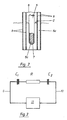
- FIG. 1 shows a reservoir 1 which is filled to a level 2 with a brake fluid.
- the reservoir 1 has on its top a filler neck 3, which is closed by a lid 4.
- the cover 4 consists of an electrically insulating plastic and has two electrodes 5 and 6 on its underside.
- the electrode 5 is a rod-shaped inner electrode and the electrode 6 is a tubular outer electrode coaxially surrounding the inner electrode 5.
- Both electrodes are made of titanium and have a cover layer 7 or 8 made of titanium dioxide, which can be formed by allowing the titanium to oxidize in air.
- the cover layers 7 and 8 are conductive and so dense that they do not contain any brake fluid let in. Only the non-oxidized core 5a or 6a of the electrodes is electrically conductive.
- the electrodes are both immersed in the brake fluid.
- the electrodes 5 and 6 are each connected to an electrical line 9 and 10, which are passed through the cover 4 and lead to an electronic circuit 11.
- the inner electrode 5 has a diameter of 4 mm
- the outer electrode 6 has an inner diameter of 10 mm
- both electrodes are 40 mm long and their cover layer 7 or 8 made of titanium is a few ⁇ m thick. This enables immersion depths between 10 mm and 25 mm and water content in brake fluid of less than 0.05% to be determined.
- FIG. 3 shows the equivalent circuit diagram of this arrangement. It consists of this circuit 11 and two capacitors C1 and C2 and an ohmic resistor R in series connection.
- the circuit 11 serves to determine the complex impedance
- the capacitance C1 is the capacitance of the capacitor, which is formed by the core 5a of the inner electrode as the first electrode, the brake fluid in the electrode arrangement up to level 2 as the counter electrode and the cover layer 7 as the dielectric.
- the capacitance C2 is the capacitance of the capacitor, which is formed by the core 6a of the outer electrode as the first electrode, by the brake fluid up to level 2 as the counter electrode and by the cover layer 8 as the dielectric.
- R is the ohmic resistance of the brake fluid in the outer electrode.
- the capacitance C1 + C2 depends solely on the effective electrode area, that is the surface of the electrodes 5 and 6 wetted by the brake fluid, that is to say only on the immersion depth of the electrodes 5 and 6 in the brake fluid.
- the ohmic resistance R depends on the immersion depth of the electrodes in the brake fluid and on their current specific resistance.
- C1 + C2 is determined by supplying the electrode arrangement with an alternating current, the frequency of which is so low that the capacitive reactance is large against the ohmic effective resistance R.
- the reactance is a direct measure of the immersion depth of the electrodes in the brake fluid and thus for the level 2 to be determined.
- the active resistance R is determined by feeding the electrode arrangement with an alternating current, the frequency f 2 of which is so large that the active resistance R is large is against the capacitive reactance.
- the effective resistance R is smaller, the greater the immersion depth of the electrodes 5 and 6.
- the effective resistance R is inversely proportional to the immersion depth.
- the specific resistance of the brake fluid can therefore be determined from the measured resistance and the immersion depth previously determined at the frequency f 1.
- the specific resistance of the brake fluid depends on its water content; the dependency is known or can be determined empirically for a given brake fluid. By comparing the measured specific resistance with the known or empirically determined characteristic curve, which indicates the dependence of the specific resistance on the water content, the water content can thus be determined and displayed. The easiest way to do this is to use a microcomputer.
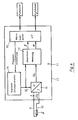
- FIG. 4 shows the block diagram of a circuit 11 suitable for this purpose.
- the electrode arrangement is shown schematically as an impedance Z , which is connected by the connecting lines 9 and 10 to the circuit 11 arranged on a circuit board 12.
- the circuit 11 consists essentially of an impedance measuring circuit 13, a digital sine generator 14, a current / voltage converter 15 and an evaluation circuit in the form of a microcomputer 16.
- the digital sine generator 14 supplies AC voltages U I with the frequencies f 1 and f 2, in which the frequency setting is effected by the microcomputer 16.
- the output of the sine wave generator 14 is connected on the one hand to the current / voltage converter 15 and on the other hand to the impedance measuring circuit 13.
- the current / voltage converter 15 feeds a current I corresponding to the voltage U I into the electrode arrangement with the impedance Z to be determined. Accordingly, the AC voltage U s falling across the electrode arrangement, which is shifted in phase by an angle ⁇ in relation to the voltage U I , is communicated to the input of the impedance measuring circuit 13, which determines the active component of the impedance Z from the ratio U s / U I also determines the phase shift ⁇ . Examples of how such an impedance measurement can be carried out can be found in the europ. Patent application 87 118 435.4. From the active component of the impedance and the phase shift ⁇ , the microcomputer 16 calculates the reactive component of the impedance in a manner known per se and evaluates the active component and the reactive component - as stated above - to output the fill level and water content.
Landscapes
- Physics & Mathematics (AREA)
- Engineering & Computer Science (AREA)
- Power Engineering (AREA)
- General Physics & Mathematics (AREA)
- Thermal Sciences (AREA)
- Fluid Mechanics (AREA)
- Chemical & Material Sciences (AREA)
- Electromagnetism (AREA)
- Chemical Kinetics & Catalysis (AREA)
- Mechanical Engineering (AREA)
- Transportation (AREA)
- Electrochemistry (AREA)
- Health & Medical Sciences (AREA)
- Life Sciences & Earth Sciences (AREA)
- Analytical Chemistry (AREA)
- Biochemistry (AREA)
- General Health & Medical Sciences (AREA)
- Immunology (AREA)
- Pathology (AREA)
- Investigating Or Analyzing Materials By The Use Of Electric Means (AREA)
- Measurement Of Levels Of Liquids Or Fluent Solid Materials (AREA)
Applications Claiming Priority (2)
| Application Number | Priority Date | Filing Date | Title |
|---|---|---|---|
| DE3812687A DE3812687A1 (de) | 1988-04-16 | 1988-04-16 | Kapazitiver sensor zum bestimmen des niveaus einer fluessigkeit in einem behaelter |
| DE3812687 | 1988-04-16 |
Publications (3)
| Publication Number | Publication Date |
|---|---|
| EP0338400A2 true EP0338400A2 (fr) | 1989-10-25 |
| EP0338400A3 EP0338400A3 (fr) | 1991-02-06 |
| EP0338400B1 EP0338400B1 (fr) | 1994-08-10 |
Family
ID=6352117
Family Applications (1)
| Application Number | Title | Priority Date | Filing Date |
|---|---|---|---|
| EP89106489A Expired - Lifetime EP0338400B1 (fr) | 1988-04-16 | 1989-04-12 | Capteur capacitif pour la détermination du niveau d'un liquide dans un réservoir |
Country Status (2)
| Country | Link |
|---|---|
| EP (1) | EP0338400B1 (fr) |
| DE (2) | DE3812687A1 (fr) |
Cited By (23)
| Publication number | Priority date | Publication date | Assignee | Title |
|---|---|---|---|---|
| WO1996024030A1 (fr) * | 1995-02-02 | 1996-08-08 | Abbott Laboratories | Equipement et procede de verification de volumes |
| WO1998012513A1 (fr) * | 1996-09-17 | 1998-03-26 | Pharmacia & Upjohn Ab | Dispositif servant a detecter le moment du contact d'une sonde d'analyse avec une surface de liquide |
| EP0856724A1 (fr) * | 1997-01-31 | 1998-08-05 | Canon Kabushiki Kaisha | Procédé et dispositif de détermination de la quantité de produit présent dans un réservoir, réservoir de produit et dispositif de traitement de signaux électriques destinés à un tel dispositif de détermination |
| FR2765334A1 (fr) * | 1997-06-27 | 1998-12-31 | Canon Kk | Procede et dispositif de controle de l'etat operationnel d'un reservoir, par exemple un reservoir d'encre |
| US6408693B1 (en) | 2000-10-04 | 2002-06-25 | Arthur G. Drinkwater | Fluid level indicating device for any container |
| EP1255107A2 (fr) * | 2001-05-04 | 2002-11-06 | Delphi Technologies, Inc. | Capteur de mesure du niveau et de l'état d'huile |
| WO2003046490A1 (fr) * | 2001-11-27 | 2003-06-05 | Endress + Hauser Gmbh+Co. Kg | Procede de mesure capacitive d'un niveau |
| WO2003050479A1 (fr) * | 2001-12-12 | 2003-06-19 | Endress + Hauser Gmbh + Co.Kg | Système électronique d'appareil de terrain comportant une unité de détection pour la technique de mesures industrielles |
| WO2003050480A1 (fr) * | 2001-12-12 | 2003-06-19 | Endress + Hauser Gmbh + Co. Kg | Equipement electronique d'appareil de champ comportant une unite capteur pour les mesures capacitives de niveau d'un conteneur |
| EP1400787A1 (fr) * | 2002-09-17 | 2004-03-24 | Nanmat Technology Co., Ltd. | Procédé de détection de la variation d'une quantité d'un produit chimique liquide de haute pureté et dispositifs pour réaliser le procédé |
| WO2004102133A2 (fr) * | 2003-05-16 | 2004-11-25 | Endress+Hauser Gmbh+Co. Kg | Mesure de niveau capacitive |
| DE202007014056U1 (de) | 2007-10-09 | 2008-12-18 | A.B.S. Silo- und Förderanlagen GmbH | Füllstandsmessvorrichtung für flexible Silos |
| DE202007014057U1 (de) | 2007-10-09 | 2008-12-18 | Delox Elektronik Gmbh | Füllstandsmessvorrichtung für festwandige Behälter |
| US7555394B2 (en) | 2003-09-17 | 2009-06-30 | Analog Devices, Inc. | Measuring circuit and a method for determining a characteristic of the impedance of a complex impedance element for facilitating characterization of the impedance thereof |
| EP2238440A2 (fr) * | 2008-01-09 | 2010-10-13 | DirAction, LLC | Séparation de phases automatisée et capteur de qualité de carburant |
| CN102052951A (zh) * | 2010-11-12 | 2011-05-11 | 天津大学 | 一种基于双模态传感器的多相界面液位的测量装置与方法 |
| FR2958605A1 (fr) * | 2010-04-09 | 2011-10-14 | Peugeot Citroen Automobiles Sa | Dispositif et procede de commande d'un systeme de freinage |
| WO2012093242A1 (fr) * | 2011-01-04 | 2012-07-12 | Avelec Limited | Appareil de capteur de niveau de fluide |
| EP2619529A4 (fr) * | 2010-09-24 | 2017-03-22 | The Marketing Store Worldwide, LP | Dispositif de détection de liquide sans contact |
| US10082546B2 (en) | 2006-12-11 | 2018-09-25 | Quasar Federal Systems | Compact underwater electromagnetic measurement system using magnetic sensors and electrical sensors having capacitive electrodes |
| EP3816591A1 (fr) * | 2019-10-28 | 2021-05-05 | Robert Bosch GmbH | Dispositif récipient, véhicule |
| DE102022209515A1 (de) | 2022-09-12 | 2024-03-14 | Knipping Kunststofftechnik Gessmann Gmbh | Füllstandmesssensor |
| DE102023208822A1 (de) | 2022-09-12 | 2024-05-23 | Knipping Kunststofftechnik Gessmann Gmbh | Füllstandmesssensor |
Families Citing this family (18)
| Publication number | Priority date | Publication date | Assignee | Title |
|---|---|---|---|---|
| DE4023336A1 (de) * | 1990-07-23 | 1992-02-06 | Hessberg Sigfried | Geraet zur ueberwachung von aus einem katheter austretender koerperfluessigkeit |
| DE4105857C2 (de) * | 1991-02-25 | 1994-07-07 | Claas Ohg | Vorrichtung zur Messung eines Massestromes |
| DE19528384C2 (de) * | 1995-08-02 | 1999-09-30 | Ulrich Pok | Kapazitive Meßeinrichtung zur kontinuierlichen Standregelung für Medien unterschiedlicher Dielektrizitätskonstanten |
| DE29613141U1 (de) * | 1996-07-29 | 1996-09-19 | Gattringer Michael | Füllstandsgeber |
| WO1998033044A1 (fr) | 1997-01-28 | 1998-07-30 | Abb Research Ltd. | Detecteur de niveau capacitif a geometrie d'electrodes optimisee |
| DE19713267A1 (de) * | 1997-01-28 | 1998-07-30 | Abb Research Ltd | Verfahren zur Bestimmung der Dielektrizitätskonstante und/oder der Leitfähigkeit mindestens eines Mediums sowie Vorrichtung zur Durchführung des Verfahrens |
| DE19755418A1 (de) * | 1997-12-12 | 1999-06-24 | Fraunhofer Ges Forschung | Sensorelement und Vorrichtung zur Messung komplexer Impedanzen sowie Verwendung der Vorrichtung |
| DE19755417C2 (de) * | 1997-12-12 | 1999-11-04 | Fraunhofer Ges Forschung | Auswerteschaltung zur Ermittlung komplexer Impedanzen, Vorrichtung zur Messung komplexer Impedanzen und Verwendung der Vorrichtung |
| DE19757190A1 (de) * | 1997-12-22 | 1999-06-24 | Abb Research Ltd | Kapazitiver Füllstandssensor mit integrierter Schmutzfilmdetektion |
| DE19851213C1 (de) * | 1998-11-06 | 2000-06-08 | Daimler Chrysler Ag | Kapazitive Sensoranordnung für ein als Dielektrikum wirkendes flüssiges oder gasförmiges Medium |
| US7134330B2 (en) | 2003-05-16 | 2006-11-14 | Endress + Hauser Gmbh + Co. Kg | Capacitive fill level meter |
| DE102005027344A1 (de) | 2005-06-13 | 2007-01-04 | Ifm Electronic Gmbh | Kapazitives Füllstandsmess- bzw. -erkennungsgerät |
| DE102008006931A1 (de) | 2008-01-31 | 2009-08-13 | Daimler Ag | Sensor zur Erfassung eines Füllstands einer Flüssigkeit in einem Behälter und Brennstoffzellensystem mit einem derartigen Sensor |
| DE202011101482U1 (de) * | 2011-06-06 | 2012-09-07 | Robert Seuffer Gmbh & Co. Kg | Vorrichtung zur Erfassung von Materialeigenschaften |
| DE202012000569U1 (de) * | 2012-01-20 | 2013-04-23 | Seuffer Gmbh & Co.Kg | Sensorvorrichtung zur Erfassung von Flüssigkeitseigenschaften |
| DE102016009879A1 (de) * | 2016-08-10 | 2018-02-15 | Tedrive Steering Systems Gmbh | Verfahren und Vorrichtung zur Bestimmung der Leckrate einer hydraulischen Komponente eines Fahrzeugs und dessen Restreichweite |
| DE102019210123A1 (de) * | 2019-07-09 | 2021-01-14 | Zf Friedrichshafen Ag | System und Verfahren zum Erfassen eines Ölzustands |
| DE102021115222A1 (de) * | 2021-06-11 | 2022-12-15 | Kyocera Avx Components (Werne) Gmbh | Sensorvorrichtung und Verfahren zur Erfassung von Eigenschaften einer Flüssigkeit |
Citations (7)
| Publication number | Priority date | Publication date | Assignee | Title |
|---|---|---|---|---|
| NL6714416A (fr) * | 1966-10-26 | 1968-04-29 | ||
| DE2319008A1 (de) * | 1973-04-14 | 1974-10-31 | Friedrich Mahne | Anordnung zur kontrolle des bremsfluessigkeitsstandes bei kraftfahrzeugbremsanlagen |
| NL7603909A (en) * | 1976-04-13 | 1977-10-17 | Mattheus Gijsbertus Jozef Arts | Fluid level measuring catheter - has oblong body with measuring devices at end connected to gauges |
| DE3322657A1 (de) * | 1983-06-23 | 1985-01-10 | VEGA Grieshaber GmbH & Co, 7620 Wolfach | Vorrichtung zur ueberwachung einer laenglichen, fuer die kapazitive fuellstandsmessung in einem behaelter vorgesehenen sonde auf abriss |
| WO1985004718A1 (fr) * | 1984-04-06 | 1985-10-24 | Fraunhofer-Gesellschaft Zur Förderung Der Angewand | Detecteur pour l'analyse de liquides |
| EP0271849A2 (fr) * | 1986-12-19 | 1988-06-22 | DODUCO KG. Dr. Eugen Dürrwächter | Dispositif pour la mesure d'impédance pour la mesure du chargement d'impédance d'un détecteur capacitif en le trampant dans un fluide |
| EP0288215A2 (fr) * | 1987-04-24 | 1988-10-26 | Simmonds Precision Products Inc. | Détermination de capacité et de résistance électriques |
Family Cites Families (3)
| Publication number | Priority date | Publication date | Assignee | Title |
|---|---|---|---|---|
| CH521574A (de) * | 1970-12-08 | 1972-04-15 | Endress Hauser Gmbh Co | Füllstandsmessvorrichtung |
| DE2521687C3 (de) * | 1975-05-15 | 1980-04-30 | Endress U. Hauser Gmbh U. Co, 7867 Maulburg | Meßwertwandler zur kapazitiven Füllstandsmessung |
| CH632089A5 (en) * | 1978-06-15 | 1982-09-15 | Alusuisse | Filling level measuring probe for an electrically conductive medium |
-
1988
- 1988-04-16 DE DE3812687A patent/DE3812687A1/de not_active Withdrawn
-
1989
- 1989-04-12 DE DE58908161T patent/DE58908161D1/de not_active Expired - Fee Related
- 1989-04-12 EP EP89106489A patent/EP0338400B1/fr not_active Expired - Lifetime
Patent Citations (7)
| Publication number | Priority date | Publication date | Assignee | Title |
|---|---|---|---|---|
| NL6714416A (fr) * | 1966-10-26 | 1968-04-29 | ||
| DE2319008A1 (de) * | 1973-04-14 | 1974-10-31 | Friedrich Mahne | Anordnung zur kontrolle des bremsfluessigkeitsstandes bei kraftfahrzeugbremsanlagen |
| NL7603909A (en) * | 1976-04-13 | 1977-10-17 | Mattheus Gijsbertus Jozef Arts | Fluid level measuring catheter - has oblong body with measuring devices at end connected to gauges |
| DE3322657A1 (de) * | 1983-06-23 | 1985-01-10 | VEGA Grieshaber GmbH & Co, 7620 Wolfach | Vorrichtung zur ueberwachung einer laenglichen, fuer die kapazitive fuellstandsmessung in einem behaelter vorgesehenen sonde auf abriss |
| WO1985004718A1 (fr) * | 1984-04-06 | 1985-10-24 | Fraunhofer-Gesellschaft Zur Förderung Der Angewand | Detecteur pour l'analyse de liquides |
| EP0271849A2 (fr) * | 1986-12-19 | 1988-06-22 | DODUCO KG. Dr. Eugen Dürrwächter | Dispositif pour la mesure d'impédance pour la mesure du chargement d'impédance d'un détecteur capacitif en le trampant dans un fluide |
| EP0288215A2 (fr) * | 1987-04-24 | 1988-10-26 | Simmonds Precision Products Inc. | Détermination de capacité et de résistance électriques |
Non-Patent Citations (2)
| Title |
|---|
| JOURNAL OF PHYSICS E. SCIENTIFIC INSTRUMENTS. vol. 16, no. 9, September 1983, ISHING, BRISTOL GB Seiten 827 - 828; P.I. ROSS: "A WATER-LEVEL SENSOR USING A CAPACITANCE TO FREQUENCY CONVERTER" * |
| MEASUREMENT AND CONTROL. vol. 21, no. 1, Februar 1988, LONDON GB Seiten 15 - 19; N. WATMOUGH: "CAPACITANCE FOR LEVEL MEASUREMENT" * |
Cited By (34)
| Publication number | Priority date | Publication date | Assignee | Title |
|---|---|---|---|---|
| WO1996024030A1 (fr) * | 1995-02-02 | 1996-08-08 | Abbott Laboratories | Equipement et procede de verification de volumes |
| WO1998012513A1 (fr) * | 1996-09-17 | 1998-03-26 | Pharmacia & Upjohn Ab | Dispositif servant a detecter le moment du contact d'une sonde d'analyse avec une surface de liquide |
| US6328934B1 (en) | 1996-09-17 | 2001-12-11 | Pharmacia Ab | Device for detection of when a test probe gets into contact with a liquid surface |
| EP0856724A1 (fr) * | 1997-01-31 | 1998-08-05 | Canon Kabushiki Kaisha | Procédé et dispositif de détermination de la quantité de produit présent dans un réservoir, réservoir de produit et dispositif de traitement de signaux électriques destinés à un tel dispositif de détermination |
| FR2759165A1 (fr) * | 1997-01-31 | 1998-08-07 | Canon Kk | Procede et dispositif de determination de la quantite de produit present dans un reservoir, reservoir de produit et dispositif de traitement de signaux electriques destines a un tel dispositif de determination |
| US6345532B1 (en) | 1997-01-31 | 2002-02-12 | Canon Kabushiki Kaisha | Method and device for determining the quantity of product present in a reservoir, a product reservoir and a device for processing electrical signals intended for such a determination device |
| FR2765334A1 (fr) * | 1997-06-27 | 1998-12-31 | Canon Kk | Procede et dispositif de controle de l'etat operationnel d'un reservoir, par exemple un reservoir d'encre |
| US6164744A (en) * | 1997-06-27 | 2000-12-26 | Canon Kabushiki Kaisha | Method and device for monitoring the operational state of a reservoir, for example an ink reservoir |
| US6408693B1 (en) | 2000-10-04 | 2002-06-25 | Arthur G. Drinkwater | Fluid level indicating device for any container |
| EP1255107A2 (fr) * | 2001-05-04 | 2002-11-06 | Delphi Technologies, Inc. | Capteur de mesure du niveau et de l'état d'huile |
| WO2003046490A1 (fr) * | 2001-11-27 | 2003-06-05 | Endress + Hauser Gmbh+Co. Kg | Procede de mesure capacitive d'un niveau |
| CN1293365C (zh) * | 2001-12-12 | 2007-01-03 | 恩德莱斯和豪瑟尔两合公司 | 具有用于容器中容性料位测量的传感器单元的电子现场设备 |
| WO2003050480A1 (fr) * | 2001-12-12 | 2003-06-19 | Endress + Hauser Gmbh + Co. Kg | Equipement electronique d'appareil de champ comportant une unite capteur pour les mesures capacitives de niveau d'un conteneur |
| WO2003050479A1 (fr) * | 2001-12-12 | 2003-06-19 | Endress + Hauser Gmbh + Co.Kg | Système électronique d'appareil de terrain comportant une unité de détection pour la technique de mesures industrielles |
| US7415366B2 (en) | 2001-12-12 | 2008-08-19 | Endress + Hauser Gmbh + Co. Kg | Electronic field device with a sensor unit for capacitive level measurement in a container |
| EP1400787A1 (fr) * | 2002-09-17 | 2004-03-24 | Nanmat Technology Co., Ltd. | Procédé de détection de la variation d'une quantité d'un produit chimique liquide de haute pureté et dispositifs pour réaliser le procédé |
| WO2004102133A2 (fr) * | 2003-05-16 | 2004-11-25 | Endress+Hauser Gmbh+Co. Kg | Mesure de niveau capacitive |
| WO2004102133A3 (fr) * | 2003-05-16 | 2005-02-10 | Endress & Hauser Gmbh & Co Kg | Mesure de niveau capacitive |
| CN100432636C (zh) * | 2003-05-16 | 2008-11-12 | 恩德莱斯和豪瑟尔两合公司 | 电容式料位测量 |
| CN100541207C (zh) * | 2003-09-17 | 2009-09-16 | 阿纳洛格装置公司 | 确定复合阻抗元件的阻抗的特性以便于其阻抗的表征的测量电路和方法 |
| US7555394B2 (en) | 2003-09-17 | 2009-06-30 | Analog Devices, Inc. | Measuring circuit and a method for determining a characteristic of the impedance of a complex impedance element for facilitating characterization of the impedance thereof |
| US10082546B2 (en) | 2006-12-11 | 2018-09-25 | Quasar Federal Systems | Compact underwater electromagnetic measurement system using magnetic sensors and electrical sensors having capacitive electrodes |
| DE202007014056U1 (de) | 2007-10-09 | 2008-12-18 | A.B.S. Silo- und Förderanlagen GmbH | Füllstandsmessvorrichtung für flexible Silos |
| DE202007014057U1 (de) | 2007-10-09 | 2008-12-18 | Delox Elektronik Gmbh | Füllstandsmessvorrichtung für festwandige Behälter |
| EP2238440A4 (fr) * | 2008-01-09 | 2013-11-20 | Diraction Llc | Séparation de phases automatisée et capteur de qualité de carburant |
| EP2238440A2 (fr) * | 2008-01-09 | 2010-10-13 | DirAction, LLC | Séparation de phases automatisée et capteur de qualité de carburant |
| FR2958605A1 (fr) * | 2010-04-09 | 2011-10-14 | Peugeot Citroen Automobiles Sa | Dispositif et procede de commande d'un systeme de freinage |
| EP2619529A4 (fr) * | 2010-09-24 | 2017-03-22 | The Marketing Store Worldwide, LP | Dispositif de détection de liquide sans contact |
| CN102052951B (zh) * | 2010-11-12 | 2012-07-04 | 天津大学 | 一种基于双模态传感器的多相界面液位的测量装置与方法 |
| CN102052951A (zh) * | 2010-11-12 | 2011-05-11 | 天津大学 | 一种基于双模态传感器的多相界面液位的测量装置与方法 |
| WO2012093242A1 (fr) * | 2011-01-04 | 2012-07-12 | Avelec Limited | Appareil de capteur de niveau de fluide |
| EP3816591A1 (fr) * | 2019-10-28 | 2021-05-05 | Robert Bosch GmbH | Dispositif récipient, véhicule |
| DE102022209515A1 (de) | 2022-09-12 | 2024-03-14 | Knipping Kunststofftechnik Gessmann Gmbh | Füllstandmesssensor |
| DE102023208822A1 (de) | 2022-09-12 | 2024-05-23 | Knipping Kunststofftechnik Gessmann Gmbh | Füllstandmesssensor |
Also Published As
| Publication number | Publication date |
|---|---|
| DE58908161D1 (de) | 1994-09-15 |
| DE3812687A1 (de) | 1989-10-26 |
| EP0338400A3 (fr) | 1991-02-06 |
| EP0338400B1 (fr) | 1994-08-10 |
Similar Documents
| Publication | Publication Date | Title |
|---|---|---|
| EP0338400B1 (fr) | Capteur capacitif pour la détermination du niveau d'un liquide dans un réservoir | |
| EP1348108A1 (fr) | Procede et dispositif de mesure de niveaux | |
| DE2515065C2 (de) | Standhöhen-Meßgerät für Flüssigkeits-Behälter | |
| DE2645716C2 (de) | Einrichtung zum kontinuierlichen Messen des Flüssigkeitsstandes in einem Behälter | |
| EP1204848B1 (fr) | Procede de mesure du niveau de remplissage et detecteur du niveau de remplissage | |
| DE3714306A1 (de) | Kapazitiver pegelanzeiger | |
| DE19645970C2 (de) | Kapazitiver Füllstandsensor zum Erfassen des Füllstandes eines innerhalb eines Behälters befindlichen Fluids | |
| DE19949985A1 (de) | Kapazitiver Sensor zur Detektion des Füllstandes eines Mediums in einem Behälter | |
| WO1996035929A1 (fr) | Detecteur capacitif de niveau | |
| DE3114678C2 (de) | Füllstandsanzeiger für stromleitende Flüssigkeiten und Schüttgut | |
| DE102010030362A1 (de) | Vorrichtung und Verfahren zur kapazitiven Bestimmung eines Füllstandes einer Flüssigkeit in einem Behälter | |
| DE19816455A1 (de) | Füllstandssensor | |
| DE3524250A1 (de) | Anordnung zur kontrolle des fuellstandes eines tintenbehaelters | |
| DE4025400C1 (fr) | ||
| DE10063557B4 (de) | Verfahren und Vorrichtung zum Messen von Pegelständen | |
| DE2819731C2 (de) | Anordnung zur kapazitiven Füllstandsmessung in einem Behälter | |
| EP0679863B2 (fr) | Dispositif de mesure de la position d'un conducteur d'un câble dans la gaine de câble | |
| DE102018101206A1 (de) | Sondeneinheit | |
| EP1521066A1 (fr) | Système de mesure capacitive de niveau | |
| DE10309769B4 (de) | Anordnung zur Bestimmung von Zustandsgrößen für Flüssigkeiten in einem geschlossenen nichtmetallischen Behälter | |
| EP0927877B1 (fr) | Dispositif de mesure pour une jauge carburant | |
| DE1498404A1 (de) | Kapazitive Messsonde zur Bestimmung der Niveauhoehe von Fluessigkeiten und Festguetern mit begrenzter Ausdehnung des elektrischen Feldes | |
| EP1521065A1 (fr) | Procédé de mesure de niveau de remplissage d'un récipient et un dispositif de mesure correspondant | |
| DE3422394C2 (fr) | ||
| EP0724140B1 (fr) | Procédé et dispositif pour l'évaluation des signaux d'un capteur de niveau capacitif |
Legal Events
| Date | Code | Title | Description |
|---|---|---|---|
| PUAI | Public reference made under article 153(3) epc to a published international application that has entered the european phase |
Free format text: ORIGINAL CODE: 0009012 |
|
| AK | Designated contracting states |
Kind code of ref document: A2 Designated state(s): DE ES FR GB IT SE |
|
| PUAL | Search report despatched |
Free format text: ORIGINAL CODE: 0009013 |
|
| AK | Designated contracting states |
Kind code of ref document: A3 Designated state(s): DE ES FR GB IT SE |
|
| 17P | Request for examination filed |
Effective date: 19901227 |
|
| 17Q | First examination report despatched |
Effective date: 19920320 |
|
| GRAA | (expected) grant |
Free format text: ORIGINAL CODE: 0009210 |
|
| AK | Designated contracting states |
Kind code of ref document: B1 Designated state(s): DE ES FR GB IT SE |
|
| PG25 | Lapsed in a contracting state [announced via postgrant information from national office to epo] |
Ref country code: IT Free format text: LAPSE BECAUSE OF FAILURE TO SUBMIT A TRANSLATION OF THE DESCRIPTION OR TO PAY THE FEE WITHIN THE PRE;WARNING: LAPSES OF ITALIAN PATENTS WITH EFFECTIVE DATE BEFORE 2007 MAY HAVE OCCURRED AT ANY TIME BEFORE 2007. THE CORRECT EFFECTIVE DATE MAY BE DIFFERENT FROM THE ONE RECORDED.SCRIBED TIME-LIMIT Effective date: 19940810 Ref country code: ES Free format text: THE PATENT HAS BEEN ANNULLED BY A DECISION OF A NATIONAL AUTHORITY Effective date: 19940810 Ref country code: GB Effective date: 19940810 Ref country code: FR Effective date: 19940810 |
|
| REF | Corresponds to: |
Ref document number: 58908161 Country of ref document: DE Date of ref document: 19940915 |
|
| PG25 | Lapsed in a contracting state [announced via postgrant information from national office to epo] |
Ref country code: SE Effective date: 19941110 |
|
| EN | Fr: translation not filed | ||
| GBV | Gb: ep patent (uk) treated as always having been void in accordance with gb section 77(7)/1977 [no translation filed] |
Effective date: 19940810 |
|
| PLBI | Opposition filed |
Free format text: ORIGINAL CODE: 0009260 |
|
| 26 | Opposition filed |
Opponent name: VDO ADOLF SCHINDLING AG Effective date: 19950505 |
|
| PLBF | Reply of patent proprietor to notice(s) of opposition |
Free format text: ORIGINAL CODE: EPIDOS OBSO |
|
| PLBF | Reply of patent proprietor to notice(s) of opposition |
Free format text: ORIGINAL CODE: EPIDOS OBSO |
|
| PLBF | Reply of patent proprietor to notice(s) of opposition |
Free format text: ORIGINAL CODE: EPIDOS OBSO |
|
| RAP2 | Party data changed (patent owner data changed or rights of a patent transferred) |
Owner name: DODUCO GMBH + CO DR. EUGEN DUERRWAECHTER I.K. |
|
| GRAH | Despatch of communication of intention to grant a patent |
Free format text: ORIGINAL CODE: EPIDOS IGRA |
|
| PLBO | Opposition rejected |
Free format text: ORIGINAL CODE: EPIDOS REJO |
|
| RAP2 | Party data changed (patent owner data changed or rights of a patent transferred) |
Owner name: DODUCO GMBH |
|
| PLBN | Opposition rejected |
Free format text: ORIGINAL CODE: 0009273 |
|
| STAA | Information on the status of an ep patent application or granted ep patent |
Free format text: STATUS: OPPOSITION REJECTED |
|
| 27O | Opposition rejected |
Effective date: 19980122 |
|
| PGFP | Annual fee paid to national office [announced via postgrant information from national office to epo] |
Ref country code: DE Payment date: 19990422 Year of fee payment: 11 |
|
| PG25 | Lapsed in a contracting state [announced via postgrant information from national office to epo] |
Ref country code: DE Free format text: LAPSE BECAUSE OF NON-PAYMENT OF DUE FEES Effective date: 20010201 |