EP0336959B1 - Vorrichtung und verfahren zum behandeln einer materialbahn - Google Patents
Vorrichtung und verfahren zum behandeln einer materialbahn Download PDFInfo
- Publication number
- EP0336959B1 EP0336959B1 EP88909925A EP88909925A EP0336959B1 EP 0336959 B1 EP0336959 B1 EP 0336959B1 EP 88909925 A EP88909925 A EP 88909925A EP 88909925 A EP88909925 A EP 88909925A EP 0336959 B1 EP0336959 B1 EP 0336959B1
- Authority
- EP
- European Patent Office
- Prior art keywords
- web
- mark
- predetermined time
- sensing
- moving
- Prior art date
- Legal status (The legal status is an assumption and is not a legal conclusion. Google has not performed a legal analysis and makes no representation as to the accuracy of the status listed.)
- Expired - Lifetime
Links
- 239000000463 material Substances 0.000 title claims abstract description 23
- 238000000034 method Methods 0.000 title claims description 17
- 238000007639 printing Methods 0.000 claims abstract description 20
- 230000007547 defect Effects 0.000 claims abstract description 17
- 239000007921 spray Substances 0.000 claims abstract description 15
- 230000002950 deficient Effects 0.000 claims abstract description 10
- 230000004044 response Effects 0.000 claims abstract description 8
- 230000000694 effects Effects 0.000 claims description 12
- 238000005507 spraying Methods 0.000 claims 1
- 230000008569 process Effects 0.000 description 8
- 239000011248 coating agent Substances 0.000 description 3
- 238000000576 coating method Methods 0.000 description 3
- 238000010586 diagram Methods 0.000 description 3
- 238000003384 imaging method Methods 0.000 description 2
- 230000014759 maintenance of location Effects 0.000 description 2
- 238000004519 manufacturing process Methods 0.000 description 2
- 230000008901 benefit Effects 0.000 description 1
- 238000004140 cleaning Methods 0.000 description 1
- 230000001419 dependent effect Effects 0.000 description 1
- 230000006870 function Effects 0.000 description 1
- 230000007246 mechanism Effects 0.000 description 1
- 238000011112 process operation Methods 0.000 description 1
- 239000002699 waste material Substances 0.000 description 1
Images
Classifications
-
- B—PERFORMING OPERATIONS; TRANSPORTING
- B65—CONVEYING; PACKING; STORING; HANDLING THIN OR FILAMENTARY MATERIAL
- B65H—HANDLING THIN OR FILAMENTARY MATERIAL, e.g. SHEETS, WEBS, CABLES
- B65H26/00—Warning or safety devices, e.g. automatic fault detectors, stop-motions, for web-advancing mechanisms
- B65H26/02—Warning or safety devices, e.g. automatic fault detectors, stop-motions, for web-advancing mechanisms responsive to presence of irregularities in running webs
-
- B—PERFORMING OPERATIONS; TRANSPORTING
- B65—CONVEYING; PACKING; STORING; HANDLING THIN OR FILAMENTARY MATERIAL
- B65H—HANDLING THIN OR FILAMENTARY MATERIAL, e.g. SHEETS, WEBS, CABLES
- B65H2404/00—Parts for transporting or guiding the handled material
- B65H2404/10—Rollers
- B65H2404/11—Details of cross-section or profile
- B65H2404/115—Details of cross-section or profile other
- B65H2404/1152—Markings, patterns
Definitions
- This invention relates to methods of the kind for processing a web of record medium material, including the step of moving said web in a first direction to effect a printing operation thereon.
- the invention also relates to systems of the kind for processing a web of record medium material, including means for moving said web in a first direction to effect a printing operation thereon.
- a roll of paper web is placed in position on a cradle at one end of the process line and the paper is unwound from the roll for use in one or more operations, such as printing, coating, imaging or other like operations on the paper.
- the paper is then rewound at the other end of the process line in either a face in or a face out manner depending upon the process and procedure employed or required in the operation.
- the rewound web is unwound at a collating location where further operations such as slitting, unit forming etc., take place, with the web material moving in the opposite direction to the press operation movement.
- defects may occur, such as a hole in the paper, a tear in the paper, a number of holes at a certain location in the paper, defective print quality, or an uneven web splice in the paper.
- the beginning and end of the double thickness web portion are sensed by a first detector device and a second detector device respectively, the outputs of the detector devices being fed via a filter to a delay device which provides a delay dependent on the paper web speed as sensed by a transducer which generates a pulse train which is applied to the delay device.
- the output of the delay device controls the operation of an inking mechanism which applies an ink mark to the double thickness web portion to indicate its unsuitability for further processing.
- a method for processing a web of record medium material including the step of moving said web in a first direction to effect a printing operation thereon, characterized by the steps of: stopping said web upon observing a defect therein, restarting movement of said web in said first direction, operating a marking device after a first predetermined time interval from said restarting to provide a mark on said web at a location corresponding to good printed web quality, said marking device being operated for a second predetermined time interval to provide said mark, operating counting means after said first predetermined time interval to count the number of print impressions effected on said web, continuing with said printing operation, moving said web in a second direction, opposite to said first direction, to effect a collating operation thereon, sensing the moving web, stopping said web in response to sensing said mark to allow for a correction operation with respect to defective printed web quality, and restarting movement of said web in said second direction to continue said collating operation.
- a system for processing a web of record medium material including means for moving said web in a first direction to effect a printing operation thereon, characterized by: means for stopping said web upon observing a defect, means for restarting movement of said web, timing means operable in response to the restarting of the movement of said web to initiate a first predetermined time interval at the termination of which marking means is operated for a second predetermined time interval to provide a mark on said web at a location corresponding to good printed web quality counting means operative after said first predetermined time interval to count the member of print impressions on said web, means for moving said web in a second direction, opposite to said first direction, to effect a collating operation thereon, sensing means for sensing said moving web, control means adapted, in response to said sensing means sensing said mark, to stop movement of said web to allow for a correction operation with respect to defective printed web quality, and restart means adapted to restart movement of said web in said second direction.
- An additional advantage of the invention is that the automatic marking of good regions of web material following defective regions avoids the possibility of the waste of web material which could arise if such marking were effected by manual means, since an operator could allow excess good material to pass before applying a manual markeT such as a strip of paper extending from the wound roll. Furthermore such manual operation could involve physical danger to the operator.
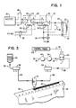
- Fig. 1 is a schematic wiring diagram of the circuitry for connecting certain devices used in a web press application or operation wherein a roll of paper or like record media is placed in position at one end of a process line.
- the paper is unwound from the roll for the accomplishment of certain operations which may include printing on the paper, coating on one or both sides of the paper, or imaging or like recording of information or data on the paper.
- certain operations may include printing on the paper, coating on one or both sides of the paper, or imaging or like recording of information or data on the paper.
- a defect in the paper or in the printing, coating or recording is discovered, it is necessary that the process line be stopped, and the defect be corrected so as to provide a quality product for the customer.
- it may be discretionary with the operator in the case of minor defects as to whether the process line is stopped. In such case the problem may be corrected at a later time or during a later operation.
- the circuitry for the press operation includes a pair of time delay relays, as 20 and 22.
- the time delay relay 20 is connected by wiring 24 to a programmable electronic counter 26 having memory retention, and the time delay relay 22 is connected by wiring 28 to a solenoid coil 30 of an air brush spray head 32.
- the time delay relays 20 and 22 are manually set to time out after respective predetermined and appropriate times.
- Wiring 34 provides a 110 volt AC supply to the coil 36 of the relay 22 and wiring 38 provides a 110 volt AC supply to the coil 40 of the relay 20.
- the time delay relay 20 includes a pair of normally open contacts 42 and 44 and the time delay relay 22 includes a set of normally open contacts 46.
- a cam actuated, single pole, microswitch 48 is provided in the wiring 24 connecting the electronic counter 26 and the time delay relay 20.
- the switch 48 operates as an input device which is used to measure impression count for the counter 26.
- a push button type switch 50 is connected to the wiring connecting one contact of the coil 36 of the time delay relay 22 and one contact of the set 46 of normally open contacts of the relay 22 to provide a test switch for the air brush spray head 32.
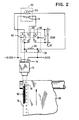
- the circuitry for the collator operation is shown in Fig. 2 and includes an illuminated push button 52 having an indicator lamp 54 and a set of normally closed contacts 56.
- the circuitry also includes a three pole double throw relay 58 having a coil 60 and a pair of normally open contacts 62 and 64 and a set of normally closed contacts 66.
- a single pole toggle switch 68 is provided in wiring 70 of a collator stop circuit and is used as a bypass switch.
- a beam type scanner 72 is connected to wiring 74 that includes a 15 volt DC supply and a connection to one side of the coil 60 of the relay 58 at pin A.
- the plus side of the 15 volt DC supply is connected to the other side of the coil 60 at pin B and the minus side of the 15 volt DC supply is connected to one terminal of the normally closed contacts 56 in the push button operator 52.
- the scanner 72 is positioned to project a beam at a spot location 76 on the marginal portion 78 of a web of paper 80.
- the spot location is focused on and aligned with a line 82 of ink spray that is applied by spray head 32 at the press operation.
- the time delay relays 20 and 22 are on-delay type and are set to time out in an arrangement based on the fastest operating collator in a particular facility.
- a preferred nominal setting for the time delay relay 20 is 30 to 50 seconds, and a nominal setting for the time delay relay 22 is 1 to 2 seconds.
- a start-to-run switch or button is actuated and 110 volts is applied through wiring 38 to the coil 40 of time delay relay 20.
- the relay 20 starts timing out for the period of 30 to 50 seconds to allow for cleaning the printing plate (plate clean-up) so as to ensure satisfactory print quality on the web 80 of paper.
- the 30 to 50 seconds is a predetermined time duration to allow for such plate clean-up and to allow for a predetermined number of satisfactory print impressions, based upon the fastest operating collator, as mentioned above.
- the contacts 42 and the contacts 44 both close.
- the closing of contacts 42 enables operation of the counter 26 through operation of the cam actuated switch 48.
- the switch 48 is actuated by suitable means (not shown) associated with each impression of the press operation. Therefore, the counter is operated in response to and counts the number of impressions.
- An impression is determined by the size of the printing plate and may be a preferred length of about 560 mm (22 inches) along the length of the web 80.
- the closing of contacts 44 of relay 20 starts the timing of the time delay relay 22.
- the operation of the time delay relay 22 starts at the instant of or simultaneously with the timing out of the time delay relay 20.
- the press is providing or passing good material.
- the relay 20 times out and contacts 46 of relay 22 close to operate the air brush spray head 32 for a period of 1 to 2 seconds to apply a mark 82 along the edge of the web 80.
- the relay 22 operates on the one shot principle in a cycle of operation. It is during the press operation that the counter 26 is counting impressions of the printing plate corresponding to repeated lengths of material. Therefore, the counter 26 is used to meter the number of impressions made in the press operation and which count information is important to the collator operation. It is, of course, understood that suitable start and stop means is provided for starting and stopping the web of paper in the process lines.
- the press operator when the press operator observes a defect in the material or the print quality of the web of paper 80 as it is being unwound from the roll, or a defect in a process operation that requires attention and needs to be corrected, the operator stops the press, determines the extent of the defect, and corrects the problem if feasible to do so at that time. The operator then restarts the press and after a predetermined amount of time has elapsed, as determined by the timing out of the respective time delay relays 20 and 22 (Fig. 1), an ink spray mark, as 82 (Figs. 2 and 3), is applied to the marginal portion 78 of the web 80.
- the ink spray mark 82 is provided to indicate the location of the defect in the web 80 and to specifically indicate the point in the web 80 at which good material is present. In effect, the mark 82 is applied after the end of the defect and at the start of good material in the web 80.
- the timing out of the time delay relay 22 sets the predetermined time that the ink spray mark 82 is applied to the moving web 80.
- the 1 to 2 second timing out of the relay 22 provides a momentary or one shot operation for marking the web 80.
- the scanner 72 detects the ink spray mark 82 along the marginal edge 78 of the web of paper 80 (Fig. 2).
- the pair of normally open contacts 62 and 64 of the three pole relay 58 are closed and the set of normally closed contacts 66 of the relay 58 are opened to effect stopping the collating machine.
- the closing of contacts 62 allows the indicator lamp 54 to be illuminated.
- the collator operator restarts the machine to continue the operation. More specifically, when the scanner 72 sees the mark 82 on the web 80, the coil 60 of the three pole relay 58 is energized, the set of contacts 62 operate to illuminate the lamp 54, and the set of contacts 64 hold the relay closed.
- the set of contacts 66 open to stop the collating machine.
- the set of contacts 56 open to release the relay 58 and the lamp 54 goes out, and the stop circuit set of contacts 66 close to allow restarting the collating machine at the next cycle of operation.
- the various devices used in the practice of the present invention include the programmable electronic counter 26 with memory retention, Durant Model No. 5882, and supplied by Eaton Corporation, Cleveland, Ohio.
- the counter is a single preset type with five digit control and is capable of counting up or down. In a preferred arrangement, the counter 26 is used to count down.
- the counter 26 is used as a predetermined batch counter to establish the roll size of paper that is going to the collator. The counter starts counting after the time that good material is going to the collator.
- the counter functions used are count down, reset to preset, single pull double throw relay outputs, relay time out operation, and automatic recycle to preset.
- the time delay relay 20 is a delay-on-make timing relay having a 0.06 to 160 second adjustable range, double pole, double throw outputs and supplied as AR2 series by Syrelec, Dallas, Texas.
- the time delay relay 22 is a single shot with single pole, double throw output and supplied as BR series by Syrelec.
- the air brush spray head 32 is No. A-AUDR-000 and supplied by Paasche Air Brush Co., Harwood Heights, Illinois.
- a one gallon plastic container for the marking ink is supplied by Paasche and the marking ink is No. 16101-K16 black ink supplied by Sanford Corporation, Bellwood, Illinois.
- Fig. 3 is a diagrammatic representation of the parts used in applying the line 82 of ink spray on the marginal portion 78 of the paper web 80.
- the one gallon plastic container 84 of ink is connected with a line 86 to an ink manifold 88, in turn connected by means of a line 90 to the spray head 32.
- An air supply line 92 is connected to a filter 94, to a regulator 96 and air is supplied through a line 98 to an air control valve 100. Air is then supplied through a line 102 to an air manifold 104 and then through a line 106 to the spray head 32.
- the several devices including the relays 20 and 22 and the counter 26 are contained in a control panel 108.
- the wiring 28 is connected as shown in Fig. 1.
- the scanner 72 is a light/dark type sensor having a convergent modulating photo cell and is available as No. SM312CV from Banner Engineering Corporation, Minneapolis, Minnesota.
- the push button 52 is a push to test/reset device, TW series as supplied by Banner.
- the relay 58 is a three pole double throw relay, No. RR3PUDC12 supplied by Banner, and an appropriate power supply is No. PS120-15 by Banner.
Landscapes
- Inking, Control Or Cleaning Of Printing Machines (AREA)
- Controlling Rewinding, Feeding, Winding, Or Abnormalities Of Webs (AREA)
- Advancing Webs (AREA)
Claims (8)
Applications Claiming Priority (2)
| Application Number | Priority Date | Filing Date | Title |
|---|---|---|---|
| US07/106,099 US4828156A (en) | 1987-10-08 | 1987-10-08 | Web monitoring system |
| US106099 | 1993-08-12 |
Publications (2)
| Publication Number | Publication Date |
|---|---|
| EP0336959A1 EP0336959A1 (de) | 1989-10-18 |
| EP0336959B1 true EP0336959B1 (de) | 1992-06-10 |
Family
ID=22309498
Family Applications (1)
| Application Number | Title | Priority Date | Filing Date |
|---|---|---|---|
| EP88909925A Expired - Lifetime EP0336959B1 (de) | 1987-10-08 | 1988-09-23 | Vorrichtung und verfahren zum behandeln einer materialbahn |
Country Status (8)
| Country | Link |
|---|---|
| US (1) | US4828156A (de) |
| EP (1) | EP0336959B1 (de) |
| JP (1) | JPH02501476A (de) |
| CA (1) | CA1301291C (de) |
| DE (1) | DE3871946T2 (de) |
| HK (1) | HK993A (de) |
| NZ (1) | NZ226265A (de) |
| WO (1) | WO1989003358A1 (de) |
Families Citing this family (14)
| Publication number | Priority date | Publication date | Assignee | Title |
|---|---|---|---|---|
| US4904875A (en) * | 1989-01-30 | 1990-02-27 | James River Corporation | Facial tissue splice detector system |
| US5365596A (en) * | 1992-12-17 | 1994-11-15 | Philip Morris Incorporated | Methods and apparatus for automatic image inspection of continuously moving objects |
| US5305392A (en) * | 1993-01-11 | 1994-04-19 | Philip Morris Incorporated | High speed, high resolution web inspection system |
| US6452679B1 (en) | 1999-12-29 | 2002-09-17 | Kimberly-Clark Worldwide, Inc. | Method and apparatus for controlling the manufacturing quality of a moving web |
| WO2005065367A2 (en) * | 2003-12-31 | 2005-07-21 | 3M Innovative Properties Company | Maximation of yield for web-based articles |
| DE102004012727A1 (de) * | 2004-03-16 | 2005-10-06 | Voith Paper Patent Gmbh | J-Linie |
| US7623699B2 (en) * | 2004-04-19 | 2009-11-24 | 3M Innovative Properties Company | Apparatus and method for the automated marking of defects on webs of material |
| EP1867979B1 (de) * | 2006-06-13 | 2009-03-11 | ABB Oy | Verfahren und Vorrichtung zur Erkennung von sich wiederholenden Mustern |
| US7859221B2 (en) | 2006-12-26 | 2010-12-28 | Honeywell International Inc. | Wireless scanner system, head and method |
| US20090028417A1 (en) * | 2007-07-26 | 2009-01-29 | 3M Innovative Properties Company | Fiducial marking for multi-unit process spatial synchronization |
| US8175739B2 (en) * | 2007-07-26 | 2012-05-08 | 3M Innovative Properties Company | Multi-unit process spatial synchronization |
| US7542821B2 (en) * | 2007-07-26 | 2009-06-02 | 3M Innovative Properties Company | Multi-unit process spatial synchronization of image inspection systems |
| US7797133B2 (en) * | 2008-09-10 | 2010-09-14 | 3M Innovative Properties Company | Multi-roller registered repeat defect detection of a web process line |
| WO2020079568A1 (en) * | 2018-10-15 | 2020-04-23 | 3M Innovative Properties Company | Method and system for automatically controlling a slitter |
Family Cites Families (7)
| Publication number | Priority date | Publication date | Assignee | Title |
|---|---|---|---|---|
| US3124289A (en) * | 1964-03-10 | Detection system | ||
| GB1077561A (en) * | 1964-02-18 | 1967-08-02 | Omron Tateisi Electronics Co | System of detecting and marking defects in a moving web |
| DE1588776A1 (de) * | 1966-09-27 | 1971-01-21 | Sironics Electro Mechanical Lt | Elektrische Kontrolleinrichtung |
| US4484079A (en) * | 1981-10-28 | 1984-11-20 | Hurletronaltair, Inc. | Registration mark detector |
| DE3325125C1 (de) * | 1983-07-12 | 1985-02-14 | Erwin Sick Gmbh Optik-Elektronik, 7808 Waldkirch | Anordnung zur Markierung von Fehlstellen an schnell laufenden Materialbahnen |
| DE3342038C1 (de) * | 1983-11-22 | 1985-03-07 | Erhardt & Leimer GmbH, 8900 Augsburg | Vorrichtung zur Erfassung von Kennzeichnungen auf sich bewegenden Kennzeichnungstraegern |
| US4700627A (en) * | 1986-01-28 | 1987-10-20 | Case-Hoyt | Method and apparatus for marking defective portions of a printed web |
-
1987
- 1987-10-08 US US07/106,099 patent/US4828156A/en not_active Expired - Lifetime
-
1988
- 1988-09-20 NZ NZ226265A patent/NZ226265A/en unknown
- 1988-09-23 DE DE8888909925T patent/DE3871946T2/de not_active Expired - Fee Related
- 1988-09-23 JP JP63509110A patent/JPH02501476A/ja active Pending
- 1988-09-23 WO PCT/US1988/003297 patent/WO1989003358A1/en not_active Ceased
- 1988-09-23 EP EP88909925A patent/EP0336959B1/de not_active Expired - Lifetime
- 1988-10-05 CA CA000579218A patent/CA1301291C/en not_active Expired - Lifetime
-
1993
- 1993-01-07 HK HK9/93A patent/HK993A/en not_active IP Right Cessation
Also Published As
| Publication number | Publication date |
|---|---|
| CA1301291C (en) | 1992-05-19 |
| NZ226265A (en) | 1989-10-27 |
| US4828156A (en) | 1989-05-09 |
| WO1989003358A1 (en) | 1989-04-20 |
| JPH02501476A (ja) | 1990-05-24 |
| HK993A (en) | 1993-01-15 |
| DE3871946T2 (de) | 1993-02-04 |
| EP0336959A1 (de) | 1989-10-18 |
| DE3871946D1 (de) | 1992-07-16 |
Similar Documents
| Publication | Publication Date | Title |
|---|---|---|
| EP0336959B1 (de) | Vorrichtung und verfahren zum behandeln einer materialbahn | |
| CA1093660A (en) | Gate control for printed web scanner | |
| JP3442370B2 (ja) | 印刷機内で検出された印刷欠陥を処理する装置 | |
| US4467589A (en) | Method and apparatus for splicing packing material webs | |
| JPS59501708A (ja) | ラベル貼付装置 | |
| USRE28732E (en) | Method of and apparatus for printing and feeding labels in a continuous web, and for verifying and cutting individual labels therefrom for application to articles | |
| US3102470A (en) | Duplicating machine with automatic controls | |
| JP3553766B2 (ja) | 印刷機の印刷用紙供給搬送装置 | |
| JPH07172683A (ja) | ロール巻き記録媒体残量検出装置 | |
| US5487333A (en) | Stencil printing device equipped with a stencil master plate ejecting device | |
| JPH0994939A (ja) | 印刷物検査装置における不良リジェクト方法 | |
| JP2002282939A (ja) | 板材の欠陥標示装置及び板材の欠陥標示方法 | |
| JP2536832Y2 (ja) | 輪転印刷機の印刷物不良部指示装置 | |
| JP2837929B2 (ja) | 原紙の補修装置 | |
| JPH0839784A (ja) | インキつぼにインキディスペンサから印刷インキを供給する方法並びにこの方法を実施する装置 | |
| JPH07209207A (ja) | エンドレスシートの不良個所検査装置 | |
| JPH02169281A (ja) | 連続紙を用いる静電記録装置 | |
| JP2509130Y2 (ja) | 欠陥印刷折丁の排出装置 | |
| JPH0797129A (ja) | ロール紙の残量検出機構及び残量検出方法 | |
| US3398454A (en) | Automatic system for web length measurement | |
| JPH0450282Y2 (de) | ||
| JPH05120679A (ja) | 磁気カード特性評価装置 | |
| JPH04232745A (ja) | オーバープリント用リール供給ロータリプレス | |
| JPH07205090A (ja) | シートの不良個所削除用作業台 | |
| JPH07206239A (ja) | シートの耳端調整装置及び方法 |
Legal Events
| Date | Code | Title | Description |
|---|---|---|---|
| PUAI | Public reference made under article 153(3) epc to a published international application that has entered the european phase |
Free format text: ORIGINAL CODE: 0009012 |
|
| AK | Designated contracting states |
Kind code of ref document: A1 Designated state(s): CH DE FR GB LI |
|
| 17P | Request for examination filed |
Effective date: 19891017 |
|
| 17Q | First examination report despatched |
Effective date: 19910326 |
|
| GRAA | (expected) grant |
Free format text: ORIGINAL CODE: 0009210 |
|
| RAP1 | Party data changed (applicant data changed or rights of an application transferred) |
Owner name: NCR INTERNATIONAL INC. |
|
| AK | Designated contracting states |
Kind code of ref document: B1 Designated state(s): CH DE FR GB LI |
|
| REF | Corresponds to: |
Ref document number: 3871946 Country of ref document: DE Date of ref document: 19920716 |
|
| ET | Fr: translation filed | ||
| PLBE | No opposition filed within time limit |
Free format text: ORIGINAL CODE: 0009261 |
|
| STAA | Information on the status of an ep patent application or granted ep patent |
Free format text: STATUS: NO OPPOSITION FILED WITHIN TIME LIMIT |
|
| 26N | No opposition filed | ||
| REG | Reference to a national code |
Ref country code: GB Ref legal event code: IF02 |
|
| PGFP | Annual fee paid to national office [announced via postgrant information from national office to epo] |
Ref country code: CH Payment date: 20020809 Year of fee payment: 15 |
|
| PGFP | Annual fee paid to national office [announced via postgrant information from national office to epo] |
Ref country code: GB Payment date: 20030623 Year of fee payment: 16 |
|
| PGFP | Annual fee paid to national office [announced via postgrant information from national office to epo] |
Ref country code: FR Payment date: 20030708 Year of fee payment: 16 |
|
| REG | Reference to a national code |
Ref country code: GB Ref legal event code: 746 Effective date: 20030624 |
|
| PGFP | Annual fee paid to national office [announced via postgrant information from national office to epo] |
Ref country code: DE Payment date: 20030918 Year of fee payment: 16 |
|
| PG25 | Lapsed in a contracting state [announced via postgrant information from national office to epo] |
Ref country code: LI Free format text: LAPSE BECAUSE OF NON-PAYMENT OF DUE FEES Effective date: 20030930 Ref country code: CH Free format text: LAPSE BECAUSE OF NON-PAYMENT OF DUE FEES Effective date: 20030930 |
|
| REG | Reference to a national code |
Ref country code: FR Ref legal event code: D6 |
|
| REG | Reference to a national code |
Ref country code: CH Ref legal event code: PL |
|
| PG25 | Lapsed in a contracting state [announced via postgrant information from national office to epo] |
Ref country code: GB Free format text: LAPSE BECAUSE OF NON-PAYMENT OF DUE FEES Effective date: 20040923 |
|
| PG25 | Lapsed in a contracting state [announced via postgrant information from national office to epo] |
Ref country code: DE Free format text: LAPSE BECAUSE OF NON-PAYMENT OF DUE FEES Effective date: 20050401 |
|
| GBPC | Gb: european patent ceased through non-payment of renewal fee |
Effective date: 20040923 |
|
| PG25 | Lapsed in a contracting state [announced via postgrant information from national office to epo] |
Ref country code: FR Free format text: LAPSE BECAUSE OF NON-PAYMENT OF DUE FEES Effective date: 20050531 |
|
| REG | Reference to a national code |
Ref country code: FR Ref legal event code: ST |