EP0336916A2 - Behälter zur Ausgabe von zwei Produkten und Verfahren zu seiner Füllung - Google Patents
Behälter zur Ausgabe von zwei Produkten und Verfahren zu seiner Füllung Download PDFInfo
- Publication number
- EP0336916A2 EP0336916A2 EP89850108A EP89850108A EP0336916A2 EP 0336916 A2 EP0336916 A2 EP 0336916A2 EP 89850108 A EP89850108 A EP 89850108A EP 89850108 A EP89850108 A EP 89850108A EP 0336916 A2 EP0336916 A2 EP 0336916A2
- Authority
- EP
- European Patent Office
- Prior art keywords
- cup
- plunger
- piston
- plunger cup
- base
- Prior art date
- Legal status (The legal status is an assumption and is not a legal conclusion. Google has not performed a legal analysis and makes no representation as to the accuracy of the status listed.)
- Withdrawn
Links
Images


Classifications
-
- B—PERFORMING OPERATIONS; TRANSPORTING
- B65—CONVEYING; PACKING; STORING; HANDLING THIN OR FILAMENTARY MATERIAL
- B65D—CONTAINERS FOR STORAGE OR TRANSPORT OF ARTICLES OR MATERIALS, e.g. BAGS, BARRELS, BOTTLES, BOXES, CANS, CARTONS, CRATES, DRUMS, JARS, TANKS, HOPPERS, FORWARDING CONTAINERS; ACCESSORIES, CLOSURES, OR FITTINGS THEREFOR; PACKAGING ELEMENTS; PACKAGES
- B65D83/00—Containers or packages with special means for dispensing contents
- B65D83/76—Containers or packages with special means for dispensing contents for dispensing fluent contents by means of a piston
- B65D83/763—Containers or packages with special means for dispensing contents for dispensing fluent contents by means of a piston the piston being actuated by a reciprocating axial motion of a shaft which engages the piston, e.g. using a ratchet mechanism
-
- B—PERFORMING OPERATIONS; TRANSPORTING
- B65—CONVEYING; PACKING; STORING; HANDLING THIN OR FILAMENTARY MATERIAL
- B65D—CONTAINERS FOR STORAGE OR TRANSPORT OF ARTICLES OR MATERIALS, e.g. BAGS, BARRELS, BOTTLES, BOXES, CANS, CARTONS, CRATES, DRUMS, JARS, TANKS, HOPPERS, FORWARDING CONTAINERS; ACCESSORIES, CLOSURES, OR FITTINGS THEREFOR; PACKAGING ELEMENTS; PACKAGES
- B65D81/00—Containers, packaging elements, or packages, for contents presenting particular transport or storage problems, or adapted to be used for non-packaging purposes after removal of contents
- B65D81/32—Containers, packaging elements, or packages, for contents presenting particular transport or storage problems, or adapted to be used for non-packaging purposes after removal of contents for packaging two or more different materials which must be maintained separate prior to use in admixture
- B65D81/325—Containers having parallel or coaxial compartments, provided with a piston or a movable bottom for discharging contents
-
- B—PERFORMING OPERATIONS; TRANSPORTING
- B65—CONVEYING; PACKING; STORING; HANDLING THIN OR FILAMENTARY MATERIAL
- B65D—CONTAINERS FOR STORAGE OR TRANSPORT OF ARTICLES OR MATERIALS, e.g. BAGS, BARRELS, BOTTLES, BOXES, CANS, CARTONS, CRATES, DRUMS, JARS, TANKS, HOPPERS, FORWARDING CONTAINERS; ACCESSORIES, CLOSURES, OR FITTINGS THEREFOR; PACKAGING ELEMENTS; PACKAGES
- B65D25/00—Details of other kinds or types of rigid or semi-rigid containers
- B65D25/38—Devices for discharging contents
- B65D25/40—Nozzles or spouts
- B65D25/42—Integral or attached nozzles or spouts
-
- B—PERFORMING OPERATIONS; TRANSPORTING
- B65—CONVEYING; PACKING; STORING; HANDLING THIN OR FILAMENTARY MATERIAL
- B65D—CONTAINERS FOR STORAGE OR TRANSPORT OF ARTICLES OR MATERIALS, e.g. BAGS, BARRELS, BOTTLES, BOXES, CANS, CARTONS, CRATES, DRUMS, JARS, TANKS, HOPPERS, FORWARDING CONTAINERS; ACCESSORIES, CLOSURES, OR FITTINGS THEREFOR; PACKAGING ELEMENTS; PACKAGES
- B65D83/00—Containers or packages with special means for dispensing contents
- B65D83/76—Containers or packages with special means for dispensing contents for dispensing fluent contents by means of a piston
- B65D83/767—Containers or packages with special means for dispensing contents for dispensing fluent contents by means of a piston the piston having an integrated dispensing opening
Definitions
- the present invention relates to dispensing containers. More particularly, the present invention relates to improved dispensing containers which are capable of simultaneously dispensing at least two of the same or different products therefrom.
- 4,205,766 includes a transfer tube integrally formed along the wall of the upper or plunger cup, and a piston 14 which includes a cut-out portion for accommodating the transfer tube. In other embodiments this device also includes locking means for holding the plunger cup in its desired position.
- the improved device shown in my U.S. Patent No. 4,220,261 includes a central transfer tube and a piston 40 including an opening for accommodation of that transfer tube centrally thereof. This device also includes means for admitting air between the piston and the upper piston 36 to facilitate relative movement thereof.
- a dispensing container which includes a base cup, a plunger cup telescopingly received in the base cup and relatively slidable therein upon the application of pressure against the plunger cup, nozzle means communicating with both the base cup and the plunger cup, a piston which is slidable movable within the plunger cup, so that upon slidable movement of the plunger cup within the base cup a flowable product contained within the base cup can be expelled through the nozzle means and upon slidable movement of the piston within the plunger cup the flowable product contained within the plunger cup can be expelled through the nozzle means, an actuating plunger for actuating the slidable movement of the piston upon the application of pressure against the plunger cup, and priming means for preventing premature discharge of the flowable product contained within the plunger cup prior to discharge of the flowable product contained within the base cup.
- the plunger cup includes an outer surface having a predetermined outer configuration
- the base cup includes an inner surface with a corresponding predetermined inner configuration so as to facilitate slidable movement between them.
- the plunger cup include a bottom surface
- the outer surface of the plunger cup include an aperture at a location spaced from that bottom surface, so that the aperture can provide for venting of the plunger cup during filling of the plunger cup with the flowable product and for admission of air between the piston and the bottom surface of the plunger cup to facilitate dispensing of the flowable product from the plunger cup.
- the predetermined outer configuration of the outer surface of the plunger cup include at least one longitudinally extending recessed track, and in which the aperture means is located within the track
- the aperture is spaced from the bottom surface of the plunger cup a distance such that prior to the slidable movement of the plunger cup within the base cup the aperture is located adjacent to the piston, and the piston thereby covers the aperture.
- a base cup a plunger cup including a bottom surface telescopingly received in the base cup and relatively slidable therein upon the application of pressure against the plunger cup, nozzle means communicating with both the base cup and the plunger cup, a piston slidably movable within the plunger cup, so that upon slidable movement of the plunger cup within the base cup a flowable product contained within the base cup can be expelled through the nozzle means and upon slidable movement of the piston within the plunger cup a flowable product contained within the plunger cup can be expelled through the nozzle means, an actuating plunger for actuating the slidable movement of the piston upon the application of pressure against the plunger cup, and a sealing ring removably attachable to the bottom surface of the plunger cup, and including an aperture for slidable receiving and guiding the actuating plunger.
- a method for filling a dispensing container of the type described above and thus including first and second cup members with first and second flowable products for simultaneous dispensing from a common nozzle means therefor which includes telescopingly receiving the first cup member within the second cup member, filling a plunger cup member through a first end of the first cup member with the first flowable product, inserting a piston into the first end of the plunger cup member, filling the second cup member through the first end of the second cup member with the second flowable product, and sealing the first end of the second cup member.
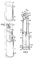
- FIG. 1 shows a dispensing container assembly constructed according to the principals of the present invention.
- the overall assembly thus primarily includes a base cup 4 and a plunger cup 2 which is telescopingly received in the base cup.
- both the base cup 4 and the plunger cup 2 are of a generally cylindrical configuration, but most importantly they have corresponding configurations so that the plunger cup is slidable within the base cup.
- the generally circular configuration of the plunger cup 2 is interrupted by arcuate indentations 5, which are guided within corresponding projections 6 at the upper end of the base cup 4 so as to guide the slidable telescoping movement between the base cup 4 and the plunger cup 2.
- the upper portion of the plunger cup 2 includes a nozzle 62 from which flowable materials contained within both the base and plunger cups can be simultaneously expelled, as will be discussed in more detail below.
- the nozzle 62 is closed by a hinged seal 3, which is also discussed below.
- the lower portion of the plunger cup 2 includes an outwardly extending annular flange 7 which is intended to bridge the distance between the outer wall of the plunger cup 2 and the inner wall of the base cup 4. The flange 7 thus acts as a seal for the purposes of slidably engaging the inner wall of base cup 4 and thus "wiping" that wall during use, as discussed more fully below.
- the plunger cup 2 includes a separate partitioned upper product chamber 26 which is intended to include one of the flowable products to be dispensed in accordance with this invention.
- Upper product chamber 26 is also of a circular or cylindrical inner configuration, preferably smooth and continuous, and it communicates directly with the nozzle 62 though a dispensing nozzle passage 36 housed in the nozzle 62.
- the plunger cup 2 also includes a separate dispensing passage 38 which runs longitudinally through the plunger cup 2 without interfering with or entering any portion of the upper product chamber 26.
- the base cup 4 is basically composed of a lower product chamber 64, again having a generally cylindrical configuration in this case corresponding to that of the base cup 4 itself.
- Lower product chamber 64 is intended to include either the same, or, more preferably, a different flowable product which is intended to be dispensed through the nozzle 62.
- the nozzle 62 of the plunger cup 2 thus provides for simultaneous discharge of the flowable materials from both the upper product chamber 26 and the lower product chamber 64.
- Dispensing passage 38 leads directly into another dispensing nozzle passage 40, and the two dispensing nozzle passages 36 and 40 thus terminate at adjacent exit points 20 and 18, respectively, separated by a wall portion 54, so that the respective flowable materials are essentially simultaneously dishcarges at that point, but are kept out of direct contact up to that point of discharge.
- the openings in the nozzle 62 themselves, that is particularly exit points 20 and 18, can be sealed by means of a hinged flap 3 which is hingedly affixed by hinge 3a to the upper portion 63 of nozzle 62 at its end.
- the hinged flap 3 thus extends hingedly and includes two inwardly projecting tab members 5a and 5b, which are intended to engage the inner wall of the exit points 18 and 20, respectively, when the hinged flap 3 is in a closed position as shown in FIG. 2 hereof. In the open position as shown in FIG. 1 the hinged flap 3 is out of the way of exit points 20 and 18, and therefore does not interfere with the flow of the flowable material therefrom.
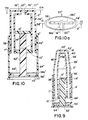
- Sealing ring 10 includes a stepped configuration which includes an upper annular portion 11 and a wider, lower annular portion 13, and in which the upper annular portion 11 includes a top annular surface 14, and the lower annular portion 13 includes a top annular surface 12. Top annular surface 14 terminates in a descending annular wall 15, and similarly top annular surface 12 terminates in descending annular wall 17.
- the diameter of upper annular portion 11, as represented by descending annular wall 15, essentially corresponds to the inner diameter of the upper product chamber 26, so that the descending annular wall 15 can frictionally engage the inner wall of upper product chamber 26. Furthermore, the diameter of lower annular portion 13, as represented by descending annular wall 17, is substantially greater than the inner diameter of product chamber 26.
- the overall sealing ring 10 is annular and includes a central opening 53.
- An activating plunger 52 having a generally cylindrical configuration, and a diameter which substantially corresponds to the diameter of the central opening 53 in the sealing ring 10, can thus be slidably movable within that central opening 53, as can best be seen in FIG. 4.
- Activating plunger 52 can either be a separate cylindrical member, or it can be integrally formed with the piston 16. In either case, however, before initial actuation of these dispensing devices, the activating plunger is initially maintained in the configuration shown in FIG. 1, whether it is integral with or in abutment with the lower surface of piston 16, and it is maintained in that position by the frictional engagement with the inner surface of central opening 53 of sealing ring 10.
- Bottom member 34 is preferably engageable with the bottom of the generally cylindrical opening in the base cup 4 for sealingly closing same. More particularly, bottom member 34 is a one-way locking ring, in that once it is in place, it should not be removable from the base cup 4. This is accomplished by the inclusion of a pair of annular beads 44 and 46 about the inner periphery of the base cap 4. As shown in FIG. 2, the longitudinal dimension of the bottom member 34 corresponds to the distance between these two annular beads 44 and 46. Therefore, by forcing the bottom member 34 over the lower annular bead 44, and into position between the upper and lower annular beads 46 and 44, respectively, the bottom member 34 becomes locked therebetween, and subsequent removal of same is prevented.
- bottom member 34 into the lower end of the base cup 4 is further facilitated by the presence of longitudinally extending beads 35 along the inner surface of the base cup 4.
- Two such longitudinally extending beads 35 are shown in FIG. 2, but any number of same can be employed. Their purpose is to separate the outer longitudinal wall 34a of the bottom member 34 from the inner wall of the base cup 4, but only for the short distance travelled by the bottom member 4 as it is being inserted into the lower end of the base cup 4, and only until it reaches its destination between the annular beads 44 and 46. Only a small such separation is required to facilitate this insertion, that is, enough separation to permit air or other gas within the lower product chamber 64 to escape therefrom.
- a similar longitudinally extending bead can be incorporated into the inner wall at the lower end of the upper product chamber 26 for the purpose of similarly facilitating the insertion of piston 16 into the lower end of the upper product chamber 26.
- these longitudinally extending beads can alternatively comprise short grooves extending along the inner walls of the upper and lower product chambers for the distance required in accordance with the above discussion thereof.
- the device is in the configuration as shown in FIGS. 1 and 2, with the upper product chamber 26 and the lower product chamber 64 being filled with flowable product. Furthermore, this configuration can be maintained, and the application of inadvertent pressure against plunger cup 2 can be avoided, by using cover cap 30.
- This cover cap 30 is generally cylindrical, and includes an upper closed end 31 and an open bottom 32. The depending side walls of cover cap 30 terminate at open bottom 32 with a flanged annular rim 33 with a diameter slightly greater than that of the base cup 4.
- cover cap 30 has an overall length which is greater than the overall length of the plunger cup 2, so that cover cap 30 can be placed over plunger cup 2, with flanged annular rim 33 resting upon the upper ledge 6 of base cup 4 without contacting plunger cup 2, even in its fully open position prior to actuation. In this manner, any inadvertent contact will be applied against cover cap 30, with no effect upon plunger cap 2, which is therefore fully protected thereby during periods of non-use.
- base cup 4 terminate in a flanged base 36, which provides increased stability to the base cup 4, and thus to the overall device, which can thus stand and remain stable in the configuration as shown in FIGS. 1 and 2.
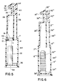
- FIG. 5 An alternative embodiment of the dispensing devices of this invention is shown in FIG. 5.
- the piston 16 and the sealing ring 10 are placed in essentially the same position as is the case in connection with the embodiment shown in FIG. 1.
- the piston 16 and the actuating plunger 52 are separate units.
- the actuating plunger 52 is initially mounted directly on the upper portion of the bottom member 34 at a location in alignment with the central passageway 53 in sealing ring 10, so that upon a downward movement of the plunger cup 2, the actuating plunger 52 will eventually enter central passageway 53 in sealing ring 10 and thus come into contact with the bottom surface of piston 16 within the upper product chamber 26 after an initial period of actuation, or "priming,” has occurred, i.e., as the distance "x" is traversed.
- the actuating plunger 52 shown in FIG. 5 can be molded as a single unit along with the bottom member 34.
- the actuating plunger 52 will likewise be properly located. It is also possible to include a circular indentation within the inner face of the bottom member 34 to snugly fit and locate the activating plunger 52 therein. Furthermore, in order to properly locate the actuating plunger 52, even in the case where actuating plunger 52 and bottom member 34 are a single unit, a registration mark or the like can be placed on the lower surface of bottom member 34 at a predetermined location which has a known relationship to the location of the actuating plunger, and to the location of the product chamber 26.
- the bottom member 34 and the side wall of the base cup 4 can include corresponding male and female members so that they must mate with each other in order to slidably interconnect, thus insuring proper orientation of the actuating plunger.
- the length of actuating plunger 52 is again less than the overall length of the base cup 4, and again by a distance "x" shown in FIG. 5.
- the distance "x" is provided so as to prevent actuation of the piston 16 within upper product chamber 26 during initial downward movement of the plunger cup 2 for a short predetermined period of time.
- the purpose of this is to effect "priming" of the dispensing passage 38 with a portion of the flowable material initially contained within the lower product chamber 64. This, in turn, can provide for simultaneous discharge of flowable product from both the upper and lower product chambers 26 and 64, respectively.
- the outer surface of the generally cylindrical plunger cup 2 surrounding the upper product chamber 26 includes a plurality of longitudinally extending recessed tracks 80, so as to produce a surface which appears to be serrated.
- the presence of these recessed tracks 80 having an overall outer surface which slidably engages a corresponding upper surface of the base cup 4, substantially assists in providing for easy slidable movement between the base cup 4 and the plunger cup 2. This is so because, instead of there being single continuous surfaces in contact with each other, a series of point contacts are provided along the intermittent outer, raised surfaces between each recessed track 80.
- a vent aperture 42 which can best be seen in FIGS. 1 and 2 hereof.
- the vent aperture 42 is preferably at a location which is displaced a short distance above the lower surface 43 of plunger cup 2, and is preferably placed at a location, as can best be seen in FIG. 2, which is initially aligned with the piston 16. In this manner, prior to any actuation of the dispensing containers hereof, the vent aperture 42 is effectively block by the piston 16, and there is no direct contact or passage between the flowable product within the upper product chamber 26 and the atmosphere. However, as soon as the piston 16 begins to move, the vent aperture 42 is uncovered, and as soon as the piston 16 passes vent aperture 42, this aperture can now act to reduce the pressure below the piston 16 and above the sealing ring 10, so as to significantly assist in facilitating further movement of the piston 16 upwardly within upper product chamber 26.
- vent aperture 42 can provide access to the upper product chamber 26. In this manner, upon initial filling of the upper product chamber 26 with flowable product, vent aperture 42 can provide for venting of any gases initially contained within the upper product chamber 26.
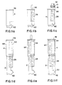
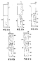
- the piston 16, sealing ring 10 and actuating plunger 52 which in the case of the embodiment shown in FIGS. 1-4 is an integral unit with piston 16, are then formed into an assembled unit, as shown in FIG. 11c.
- this assembled unit, including the piston 16 is then placed in the lower end of the upper product chamber 26, with piston 16 in frictional engagement with the inside wall thereof, and sealing ring 10 in position therebelow so as to maintain piston 16 in the proper location as is discussed below, and thus providing for sealable closure of the upper product chamber 26, and maintenance of the piston 16 in position, again as shown in FIG. 11c.
- the actuating plunger 52 is maintained in frictional engagement with the central opening 53 of sealing ring 10.
- the actuating plunger 52 is a separate unit from the piston 16.
- the plunger cup 2 can then be extended telescopingly outwardly from the base cup 4 back into the position shown in FIGS. 2 and 11d. It is then quite easy to fill the lower product chamber 64 with flowable product for use therein, and surrounding the actuating plunger 52, as shown in FIG. 11e. After such filling, the base cup 4 can then be sealed by placement of the bottom member 34 within the bottom opening for sealable engagement therewith, as shown in FIG. 11f, and the cover cap 30 can then also be applied thereto. The dispensing device of the present invention is then ready for use.
- FIGS. 12a-e An alternative filling procedure particularly adapted for filling the embodiment shown in FIG. 5 is illustrated in FIGS. 12a-e.
- the plunger cup 2 and base cup 4 can be initially maintained in their non-telescoped configuration, as shown in FIGS. 5 and 12a.
- the flange 7 at the lower end of plunger cup 2 rests against the inwardly directed flange 6 at the upper end of the base cup 4.
- This configuration of the plunger cup 2 and the base cup 4, and preferably also including the cover cap 30, can be loaded into the appropriate location in the filling apparatus.
- the upper product chamber 26 can now be filled with flowable product through the opening in the base cup 4 in the manner shown in FIG. 12b.
- the vent aperture 42 permits venting of gases within the upper product chamber 26.
- the combination of piston 16 and sealing ring 10 can then be placed into the lower opening in the upper product chamber 26 in the plunger cup 2, in the manner shown in FIG. 12c. This insertion can be facilitated by the presence of longitudinally extending beads along the inner wall at the lower end of the upper product chamber 26, in the manner discussed above.
- the lower product chamber 64 in the base cup 4 can then be filled with flowable product, again preferably a different flowable product, in the manner shown in FIG. 12d.
- the combination of bottom member 34 and actuating plunger 52 which can be an integral unit or a two-piece construction as discussed above, can then be placed into the bottom opening of the base cup 4 to sealingly engage same, in the manner shown in FIG. 12e.
- insertion of the bottom member 34 can be facilitated by the presence of longitudinally extending beads 35 along the inner wall at the lower end of the lower product chamber 64. This dispensing device is then ready for use.
- FIG. 6 hereof Another embodiment of the dispensing container of the present invention is shown in FIG. 6 hereof.
- corresponding reference numerals which include the designation ′′′ are intended to correspond to like elements in the embodiment shown in FIGS. 1-5.
- the container is specifically intended to be used only with the single flowable product in both upper product chamber 26′′′ and lower product chamber 64′′′.
- the bottom end of upper product chamber 26′′′ in this case is completely open.
- a single piston 16 as used in the previous embodiment is not employed in this case.
- piston 16′′′ are mounted along actuating rod 52′′′, in this case mounted on the bottom member 34′′′ in the manner discussed above, i.e., either as an integral unit or separately mounted thereon.
- the other elements in the container shown in FIG. 6 again correspond to those discussed above.
- the initial or uppermost one of the pistons 16′′′ will eventually enter the lower opening in the upper product chamber 26′′′ and begin to force flowable product therewithin through passage 36′′′ and into nozzle opening 18′′′.
- the upper portion of the embodiment of the dispensing device of the invention shown in FIG. 6 can be more clearly seen in FIG. 3a, and permits intermixing of the flowable product from the upper and lower dispensing chambers prior to their exit from a common nozzle 18 or 18′′′, irrespective of whether or not this is a single or two different flowable materials. This is accomplished by shortening the extension of the inner wall of the upper product chamber 26 in the plunger cup 2 so that it ends at an upper end 2b and 2b′′′, thus permitting flowable material from passages 36 and 40, and 36′′′ and 40′′′ in the case of the dispenser in FIG. 6, to intermix before they exit common exit point 18 and 18′′′, respectively.
- FIGS. 7 through 9 yet another embodiment of the dispensing container of the present invention is shown therein.
- corresponding reference numerals which include the designation ′ are intended to correspond to like elements in the embodiment shown in FIGS. 1 through 5.
- This device thus includes a base cup 4′ and a plunger cup 2′ telescopingly slidable therewithin.
- the plunger cup 2′ includes an upper nozzle 62′ for co-dispensing flowable product therefrom.
- the plunger cup 2′ in this case includes a centrally disposed upper product chamber 26′, which is again preferably circular or oval in cross-sectional configuration, and again includes a piston 16′ of comparable cross-sectional shape.
- the plunger cup 2′ includes a pair of dispensing passages 38′ extending on either side of the upper product chamber 26′, but again separate therefrom. These dispensing passages 38′ extend into corresponding nozzle passages 40′ which then join together in the manner best shown in FIG. 8, so as to exit through a U-shaped nozzle aperture 18′.
- the upper product chamber 26′ directly opens into a reduced dispensing passage 36′, which leads directly through aperture 53′ into exit aperture 20′, which as can be seen in FIG. 8, is surrounded by the U-shaped exit aperture 18′.
- aperture 42′ At a location in one of these wall portions is included aperture 42′, as can be seen in FIG. 7.
- the aperture 42′ is shown in phantom view, since it is located behind the piston 16′, in the position shown in that Figure.
- the aperture 42′ is again present for the purpose of assisting in venting upper product chamber 26′ during filling and to permit piston 16′ to proceed upwardly therethrough by allowing air to enter below the piston 16′ as it so proceeds therein.
- the base cup 4′ is this case includes an upper rim 6′ similar to that in the embodiment shown in FIGS. 1 through 5.
- the lower end 43′ of the plunger cup 2′ includes a flared outer surface 7′ for slidable contact along the inner surface of the base cup 4′ during downward slidable movement of the plunger cup 2′ therewithin.
- the base cup 4′ again includes an outwardly flared flange 36′ surrounding the bottom member 34′ for closing same.
- the piston 16′ in this case has a particular configuration, which is shown in FIGS. 7 through 9. That is, the piston 16′ in this case is again disc-shaped, and is again mounted at the lower end of upper product chamber 26′ along with and by means of the sealing ring 10′. Furthermore, mounted on the bottom member 34′ within the base cup 4′ is actuating plunger 52′, which in this case includes a rounded upper surface. The actuating plunger 52′ is again shorter than the overall length of the base cup 4′ by a distance "x′" as shown in FIG. 7.
- FIGS. 10 and 10a yet another embodiment of the dispensing container of the present invention is shown therein.
- corresponding reference numerals which include the designation ⁇ are intended to correspond to like elements in the embodiments shown in FIGS. 1-5.
- This embodiment is similar to the embodiment shown in FIGS. 7-9, with one significant difference in that the overall construction has an oval configuration, as can best be seen in FIG. 10a, as compared to the cylindrical configuration of the embodiment shown in FIGS. 7-9.
- the upper or nozzle end of this device is considerably different from that of the devices discussed above.
- This device includes a base cup 4 ⁇ and a plunger cup 2 ⁇ again telescopingly slidable therewithin.
- the plunger cup 2 ⁇ includes an upper surface which can be seen in FIG> 10a. This upper surface is open, and intended to be subsequently sealed by cover member 37 ⁇ .
- the upper surface of plunger cup 2 ⁇ thus includes a pair of openings into the pair of dispensing passages 38 ⁇ which extend on either side of the upper product chamber 26 ⁇ . It also includes a central exit aperture 20 ⁇ , which extends directly into the upper product chamber 26 ⁇ .
- the passageways 38a ⁇ and 38b ⁇ connecting the dispensing passages 38 ⁇ with the exit apertures 18 ⁇ are thus only closed when the cover member 37 ⁇ having a corresponding oval configuration is sealed to the top of the plunger cup 2 ⁇ , preferably by adhesive, or other such means.
- the other elements of the base cup 4 ⁇ and the plunger cup 2 ⁇ in this case correspond to those in the previous embodiments, including that shown in FIGS. 7-9.
Landscapes
- Engineering & Computer Science (AREA)
- Mechanical Engineering (AREA)
- Containers And Packaging Bodies Having A Special Means To Remove Contents (AREA)
- Basic Packing Technique (AREA)
- Closures For Containers (AREA)
- Package Specialized In Special Use (AREA)
Applications Claiming Priority (2)
| Application Number | Priority Date | Filing Date | Title |
|---|---|---|---|
| US07/178,274 US4961520A (en) | 1988-04-06 | 1988-04-06 | Co-dispensing container and method of filling same |
| US178274 | 1998-10-23 |
Publications (2)
| Publication Number | Publication Date |
|---|---|
| EP0336916A2 true EP0336916A2 (de) | 1989-10-11 |
| EP0336916A3 EP0336916A3 (de) | 1990-06-20 |
Family
ID=22651903
Family Applications (1)
| Application Number | Title | Priority Date | Filing Date |
|---|---|---|---|
| EP89850108A Withdrawn EP0336916A3 (de) | 1988-04-06 | 1989-04-05 | Behälter zur Ausgabe von zwei Produkten und Verfahren zu seiner Füllung |
Country Status (7)
| Country | Link |
|---|---|
| US (1) | US4961520A (de) |
| EP (1) | EP0336916A3 (de) |
| JP (1) | JPH0298570A (de) |
| KR (1) | KR900016042A (de) |
| AU (1) | AU3250789A (de) |
| FI (1) | FI891639A7 (de) |
| MX (1) | MX165487B (de) |
Cited By (5)
| Publication number | Priority date | Publication date | Assignee | Title |
|---|---|---|---|---|
| US5050774A (en) * | 1989-06-13 | 1991-09-24 | Camm James O | Combination mixer dispenser |
| US5181629A (en) * | 1989-06-13 | 1993-01-26 | Camm James O | Combination mixer dispenser |
| WO1994018092A1 (en) * | 1993-02-03 | 1994-08-18 | Philip Horsley | Container dispenser for liquids |
| GB2290521A (en) * | 1993-02-03 | 1996-01-03 | Horsleys Plastics | Container dispenser for liquids |
| WO1996026869A1 (en) * | 1995-02-27 | 1996-09-06 | James Owen Camm | Dual material dispenser comprising two containers in head to tail arrangement |
Families Citing this family (18)
| Publication number | Priority date | Publication date | Assignee | Title |
|---|---|---|---|---|
| JP2540497Y2 (ja) * | 1990-11-19 | 1997-07-02 | 株式会社吉野工業所 | 二液注出容器 |
| JP2540496Y2 (ja) * | 1990-11-19 | 1997-07-02 | 株式会社吉野工業所 | 二液注出容器 |
| JP2539991Y2 (ja) * | 1990-11-29 | 1997-07-02 | 株式会社吉野工業所 | 二液注出容器 |
| GB9118711D0 (en) * | 1991-08-31 | 1991-10-16 | Smithkline Beecham Plc | Novel device |
| US5310091A (en) * | 1993-05-12 | 1994-05-10 | Tremco, Inc. | Dual product dispenser |
| US5819987A (en) * | 1996-09-20 | 1998-10-13 | S. C. Johnson & Son, Inc. | Sprayer assembly for simultaneously dispensing multiple fluids from nested containers |
| USD402192S (en) | 1997-03-31 | 1998-12-08 | The Procter & Gamble Company | Dispenser |
| USD402193S (en) | 1997-03-31 | 1998-12-08 | The Procter & Gamble Company | Dispenser |
| USD413063S (en) | 1997-03-31 | 1999-08-24 | The Procter & Gamble Company | Nozzle |
| US6039215A (en) * | 1998-06-12 | 2000-03-21 | The Procter & Gamble Company | Dual product pump dispenser with multi-outlet closure for product separation |
| US6315171B1 (en) | 2000-09-29 | 2001-11-13 | The Plastek Group | Telescoping ram dispenser |
| ATE367362T1 (de) | 2003-06-09 | 2007-08-15 | Tah Ind Inc | Zweifachflüssigkeitskartusche |
| DE102004042665A1 (de) * | 2004-09-01 | 2006-03-02 | Ritter Gmbh | Zweikammerkartusche für zweikomponentige plastische Massen mit teleskopartig ineinanderschiebbaren Einkammerteilkartuschen |
| DE102005000757B4 (de) * | 2005-01-04 | 2007-07-19 | Ritter Gmbh | Zweikammerkartusche für zweikomponentige plastische Massen mit axial hintereinander angeordneten Kammern |
| EP1872862A1 (de) * | 2006-06-28 | 2008-01-02 | Sika Technology AG | Vorrichtung zur Abgabe von zu verarbeitendem Material und Verwendung der Vorrichtung |
| USD680858S1 (en) | 2011-03-29 | 2013-04-30 | Kraft Foods Global Brands Llc | Combined confectionary product package and dispenser |
| USD684851S1 (en) | 2011-03-29 | 2013-06-25 | Kraft Foods Global Brands Llc | Combined confectionary product package and dispenser |
| WO2021163918A1 (en) * | 2020-02-19 | 2021-08-26 | L'oreal | Device for storing and dispensing at least two cosmetic products and related method |
Family Cites Families (6)
| Publication number | Priority date | Publication date | Assignee | Title |
|---|---|---|---|---|
| US2349005A (en) * | 1943-05-05 | 1944-05-16 | Doyle L Roe | Ink eradicator applicator |
| DE1091363B (de) * | 1956-07-07 | 1960-10-20 | Schenck Gmbh Carl | Maschinenanlage zum Messen, Ausgleichen und Kontrollieren der Unwucht von Umlaufkoerpern |
| US4205766A (en) * | 1976-03-16 | 1980-06-03 | White Douglas J | Dual compartment dispensing container |
| US4050612A (en) * | 1976-05-25 | 1977-09-27 | Jules Silver | Dispensing container |
| DE2756075A1 (de) * | 1977-12-16 | 1979-06-21 | Fischer Artur Dr H C | Spritzvorrichtung zum einspritzen eines aus mehreren komponenten bestehenden aushaertbaren bindemittels in eine mauerwerksbohrung |
| US4220261A (en) * | 1978-04-19 | 1980-09-02 | White Douglas J | Dispensing container assembly |
-
1988
- 1988-04-06 US US07/178,274 patent/US4961520A/en not_active Expired - Fee Related
-
1989
- 1989-03-31 JP JP1083871A patent/JPH0298570A/ja active Pending
- 1989-04-05 MX MX015542A patent/MX165487B/es unknown
- 1989-04-05 EP EP89850108A patent/EP0336916A3/de not_active Withdrawn
- 1989-04-05 FI FI891639A patent/FI891639A7/fi not_active Application Discontinuation
- 1989-04-06 AU AU32507/89A patent/AU3250789A/en not_active Abandoned
- 1989-04-06 KR KR1019890004585A patent/KR900016042A/ko not_active Ceased
Cited By (8)
| Publication number | Priority date | Publication date | Assignee | Title |
|---|---|---|---|---|
| US5050774A (en) * | 1989-06-13 | 1991-09-24 | Camm James O | Combination mixer dispenser |
| US5181629A (en) * | 1989-06-13 | 1993-01-26 | Camm James O | Combination mixer dispenser |
| US5409140A (en) * | 1989-06-13 | 1995-04-25 | Camm; James O. | Combination mixer dispenser |
| WO1994018092A1 (en) * | 1993-02-03 | 1994-08-18 | Philip Horsley | Container dispenser for liquids |
| GB2290521A (en) * | 1993-02-03 | 1996-01-03 | Horsleys Plastics | Container dispenser for liquids |
| GB2290521B (en) * | 1993-02-03 | 1997-04-30 | Horsleys Plastics | Container dispenser for liquids |
| WO1996026869A1 (en) * | 1995-02-27 | 1996-09-06 | James Owen Camm | Dual material dispenser comprising two containers in head to tail arrangement |
| US5918770A (en) * | 1995-02-27 | 1999-07-06 | Camm; James Owen | Dual material dispenser comprising two containers in head to tail arrangement |
Also Published As
| Publication number | Publication date |
|---|---|
| AU3250789A (en) | 1989-10-12 |
| MX165487B (es) | 1992-11-13 |
| KR900016042A (ko) | 1990-11-12 |
| FI891639A0 (fi) | 1989-04-05 |
| EP0336916A3 (de) | 1990-06-20 |
| JPH0298570A (ja) | 1990-04-10 |
| US4961520A (en) | 1990-10-09 |
| FI891639A7 (fi) | 1989-10-07 |
Similar Documents
| Publication | Publication Date | Title |
|---|---|---|
| US4961520A (en) | Co-dispensing container and method of filling same | |
| US5645193A (en) | Dispensing container with telescopically arranged disposable refill cartridge and reusable base | |
| CN101674749B (zh) | 推进容器 | |
| AU2002365879B2 (en) | Aerosol valve assembly | |
| JP3305282B2 (ja) | 適量取り出しヘッド | |
| US5560518A (en) | Fluid delivery system | |
| AU669711B2 (en) | Multi-cavity dispensing refill cartridge | |
| JP2929315B2 (ja) | 真空充填法 | |
| US5335827A (en) | Multi-cavity dispensing refill cartridge | |
| JP2575914B2 (ja) | マルチキャビティ分配容器 | |
| US20020036212A1 (en) | Dispensing device and methods | |
| US20050042122A1 (en) | Device for conditioning and distributing several fluids, comprising at least two pumps | |
| NZ199131A (en) | Dispensing striped toothpaste from container using piston | |
| JPH11165101A (ja) | 二種の生成物の施与装置 | |
| EP1256526A1 (de) | Vorrichtung zur Aufbewahrung von zwei Produkten und zu deren separaten oder vermischten Druckausgabe | |
| US3656482A (en) | Applicator for dispensing substances | |
| CA2152347C (en) | A multi-cavity dispensing refill cartridge | |
| US5979708A (en) | Product dispenser having rotating base | |
| JPH0220509B2 (de) | ||
| US3300103A (en) | Aerosol dispenser with inner container | |
| EP4377225B1 (de) | Kapsel zur aufnahme und abgabe von flaschen | |
| JPH11502151A (ja) | 化粧品または香水のような物質の貯蔵およびディスペンス用装置 | |
| CA1066157A (en) | Rechargeable applicator for dispensing substances | |
| KR200182789Y1 (ko) | 디스펜서 용기 | |
| KR102523867B1 (ko) | 로터리 에어리스 컴팩트 |
Legal Events
| Date | Code | Title | Description |
|---|---|---|---|
| PUAI | Public reference made under article 153(3) epc to a published international application that has entered the european phase |
Free format text: ORIGINAL CODE: 0009012 |
|
| AK | Designated contracting states |
Kind code of ref document: A2 Designated state(s): AT BE CH DE ES FR GB GR IT LI LU NL SE |
|
| PUAL | Search report despatched |
Free format text: ORIGINAL CODE: 0009013 |
|
| AK | Designated contracting states |
Kind code of ref document: A3 Designated state(s): AT BE CH DE ES FR GB GR IT LI LU NL SE |
|
| STAA | Information on the status of an ep patent application or granted ep patent |
Free format text: STATUS: THE APPLICATION IS DEEMED TO BE WITHDRAWN |
|
| 18D | Application deemed to be withdrawn |
Effective date: 19901221 |