EP0336237A2 - Système d'emmagasinage de données et procédé pour sa fabrication - Google Patents
Système d'emmagasinage de données et procédé pour sa fabrication Download PDFInfo
- Publication number
- EP0336237A2 EP0336237A2 EP89105284A EP89105284A EP0336237A2 EP 0336237 A2 EP0336237 A2 EP 0336237A2 EP 89105284 A EP89105284 A EP 89105284A EP 89105284 A EP89105284 A EP 89105284A EP 0336237 A2 EP0336237 A2 EP 0336237A2
- Authority
- EP
- European Patent Office
- Prior art keywords
- layer
- data storage
- storage system
- control layer
- magnetization
- Prior art date
- Legal status (The legal status is an assumption and is not a legal conclusion. Google has not performed a legal analysis and makes no representation as to the accuracy of the status listed.)
- Withdrawn
Links
- 238000013500 data storage Methods 0.000 title claims abstract description 41
- 238000004519 manufacturing process Methods 0.000 title claims description 5
- 238000000034 method Methods 0.000 title 1
- 238000003860 storage Methods 0.000 claims abstract description 87
- 230000005415 magnetization Effects 0.000 claims abstract description 74
- 230000005291 magnetic effect Effects 0.000 claims abstract description 46
- 238000009826 distribution Methods 0.000 claims abstract description 22
- 239000000463 material Substances 0.000 claims description 18
- 230000005855 radiation Effects 0.000 claims description 11
- 238000001816 cooling Methods 0.000 claims description 9
- 229910000938 samarium–cobalt magnet Inorganic materials 0.000 claims description 7
- 239000011669 selenium Substances 0.000 claims description 6
- 239000000758 substrate Substances 0.000 claims description 6
- FOPBMNGISYSNED-UHFFFAOYSA-N [Fe].[Co].[Tb] Chemical compound [Fe].[Co].[Tb] FOPBMNGISYSNED-UHFFFAOYSA-N 0.000 claims description 5
- 239000010949 copper Substances 0.000 claims description 5
- KPLQYGBQNPPQGA-UHFFFAOYSA-N cobalt samarium Chemical compound [Co].[Sm] KPLQYGBQNPPQGA-UHFFFAOYSA-N 0.000 claims description 4
- RYGMFSIKBFXOCR-UHFFFAOYSA-N Copper Chemical compound [Cu] RYGMFSIKBFXOCR-UHFFFAOYSA-N 0.000 claims description 3
- BUGBHKTXTAQXES-UHFFFAOYSA-N Selenium Chemical compound [Se] BUGBHKTXTAQXES-UHFFFAOYSA-N 0.000 claims description 3
- 229910052802 copper Inorganic materials 0.000 claims description 3
- 229910052751 metal Inorganic materials 0.000 claims description 3
- 239000002184 metal Substances 0.000 claims description 3
- 229910052711 selenium Inorganic materials 0.000 claims description 3
- PMHQVHHXPFUNSP-UHFFFAOYSA-M copper(1+);methylsulfanylmethane;bromide Chemical compound Br[Cu].CSC PMHQVHHXPFUNSP-UHFFFAOYSA-M 0.000 claims description 2
- 230000005398 magnetoelastic coupling Effects 0.000 claims description 2
- 229910017052 cobalt Inorganic materials 0.000 claims 1
- 239000010941 cobalt Substances 0.000 claims 1
- VABUPYFNWNQKEQ-UHFFFAOYSA-N cobalt dysprosium iron Chemical compound [Fe][Co][Dy] VABUPYFNWNQKEQ-UHFFFAOYSA-N 0.000 claims 1
- 238000010586 diagram Methods 0.000 description 16
- 230000008859 change Effects 0.000 description 5
- 230000008878 coupling Effects 0.000 description 3
- 238000010168 coupling process Methods 0.000 description 3
- 238000005859 coupling reaction Methods 0.000 description 3
- 238000009792 diffusion process Methods 0.000 description 3
- 230000006870 function Effects 0.000 description 3
- 230000005298 paramagnetic effect Effects 0.000 description 3
- 230000010287 polarization Effects 0.000 description 3
- QHMDOPBZEZNSMZ-UHFFFAOYSA-N [Co].[Fe].[Tb].[Yb] Chemical compound [Co].[Fe].[Tb].[Yb] QHMDOPBZEZNSMZ-UHFFFAOYSA-N 0.000 description 2
- 239000011248 coating agent Substances 0.000 description 2
- 238000000576 coating method Methods 0.000 description 2
- 230000000694 effects Effects 0.000 description 2
- 230000012447 hatching Effects 0.000 description 2
- 230000003993 interaction Effects 0.000 description 2
- 230000005374 Kerr effect Effects 0.000 description 1
- 229910052771 Terbium Inorganic materials 0.000 description 1
- KYNBZKPYPKYYBQ-UHFFFAOYSA-N [Co].[Fe].[Nd] Chemical compound [Co].[Fe].[Nd] KYNBZKPYPKYYBQ-UHFFFAOYSA-N 0.000 description 1
- 229910052782 aluminium Inorganic materials 0.000 description 1
- XAGFODPZIPBFFR-UHFFFAOYSA-N aluminium Chemical compound [Al] XAGFODPZIPBFFR-UHFFFAOYSA-N 0.000 description 1
- 230000008901 benefit Effects 0.000 description 1
- 230000015572 biosynthetic process Effects 0.000 description 1
- 230000007423 decrease Effects 0.000 description 1
- 230000007547 defect Effects 0.000 description 1
- 230000008021 deposition Effects 0.000 description 1
- 239000002902 ferrimagnetic material Substances 0.000 description 1
- 239000011521 glass Substances 0.000 description 1
- 238000010438 heat treatment Methods 0.000 description 1
- 230000005381 magnetic domain Effects 0.000 description 1
- 239000000696 magnetic material Substances 0.000 description 1
- 230000005389 magnetism Effects 0.000 description 1
- 230000006641 stabilisation Effects 0.000 description 1
- 238000011105 stabilization Methods 0.000 description 1
- 230000002123 temporal effect Effects 0.000 description 1
- GZCRRIHWUXGPOV-UHFFFAOYSA-N terbium atom Chemical compound [Tb] GZCRRIHWUXGPOV-UHFFFAOYSA-N 0.000 description 1
Images

Classifications
-
- G—PHYSICS
- G11—INFORMATION STORAGE
- G11B—INFORMATION STORAGE BASED ON RELATIVE MOVEMENT BETWEEN RECORD CARRIER AND TRANSDUCER
- G11B11/00—Recording on or reproducing from the same record carrier wherein for these two operations the methods are covered by different main groups of groups G11B3/00 - G11B7/00 or by different subgroups of group G11B9/00; Record carriers therefor
- G11B11/10—Recording on or reproducing from the same record carrier wherein for these two operations the methods are covered by different main groups of groups G11B3/00 - G11B7/00 or by different subgroups of group G11B9/00; Record carriers therefor using recording by magnetic means or other means for magnetisation or demagnetisation of a record carrier, e.g. light induced spin magnetisation; Demagnetisation by thermal or stress means in the presence or not of an orienting magnetic field
- G11B11/105—Recording on or reproducing from the same record carrier wherein for these two operations the methods are covered by different main groups of groups G11B3/00 - G11B7/00 or by different subgroups of group G11B9/00; Record carriers therefor using recording by magnetic means or other means for magnetisation or demagnetisation of a record carrier, e.g. light induced spin magnetisation; Demagnetisation by thermal or stress means in the presence or not of an orienting magnetic field using a beam of light or a magnetic field for recording by change of magnetisation and a beam of light for reproducing, i.e. magneto-optical, e.g. light-induced thermomagnetic recording, spin magnetisation recording, Kerr or Faraday effect reproducing
- G11B11/10502—Recording on or reproducing from the same record carrier wherein for these two operations the methods are covered by different main groups of groups G11B3/00 - G11B7/00 or by different subgroups of group G11B9/00; Record carriers therefor using recording by magnetic means or other means for magnetisation or demagnetisation of a record carrier, e.g. light induced spin magnetisation; Demagnetisation by thermal or stress means in the presence or not of an orienting magnetic field using a beam of light or a magnetic field for recording by change of magnetisation and a beam of light for reproducing, i.e. magneto-optical, e.g. light-induced thermomagnetic recording, spin magnetisation recording, Kerr or Faraday effect reproducing characterised by the transducing operation to be executed
- G11B11/10504—Recording
- G11B11/10506—Recording by modulating only the light beam of the transducer
-
- G—PHYSICS
- G11—INFORMATION STORAGE
- G11B—INFORMATION STORAGE BASED ON RELATIVE MOVEMENT BETWEEN RECORD CARRIER AND TRANSDUCER
- G11B11/00—Recording on or reproducing from the same record carrier wherein for these two operations the methods are covered by different main groups of groups G11B3/00 - G11B7/00 or by different subgroups of group G11B9/00; Record carriers therefor
- G11B11/10—Recording on or reproducing from the same record carrier wherein for these two operations the methods are covered by different main groups of groups G11B3/00 - G11B7/00 or by different subgroups of group G11B9/00; Record carriers therefor using recording by magnetic means or other means for magnetisation or demagnetisation of a record carrier, e.g. light induced spin magnetisation; Demagnetisation by thermal or stress means in the presence or not of an orienting magnetic field
- G11B11/105—Recording on or reproducing from the same record carrier wherein for these two operations the methods are covered by different main groups of groups G11B3/00 - G11B7/00 or by different subgroups of group G11B9/00; Record carriers therefor using recording by magnetic means or other means for magnetisation or demagnetisation of a record carrier, e.g. light induced spin magnetisation; Demagnetisation by thermal or stress means in the presence or not of an orienting magnetic field using a beam of light or a magnetic field for recording by change of magnetisation and a beam of light for reproducing, i.e. magneto-optical, e.g. light-induced thermomagnetic recording, spin magnetisation recording, Kerr or Faraday effect reproducing
- G11B11/10502—Recording on or reproducing from the same record carrier wherein for these two operations the methods are covered by different main groups of groups G11B3/00 - G11B7/00 or by different subgroups of group G11B9/00; Record carriers therefor using recording by magnetic means or other means for magnetisation or demagnetisation of a record carrier, e.g. light induced spin magnetisation; Demagnetisation by thermal or stress means in the presence or not of an orienting magnetic field using a beam of light or a magnetic field for recording by change of magnetisation and a beam of light for reproducing, i.e. magneto-optical, e.g. light-induced thermomagnetic recording, spin magnetisation recording, Kerr or Faraday effect reproducing characterised by the transducing operation to be executed
- G11B11/10517—Overwriting or erasing
- G11B11/10519—Direct overwriting, i.e. performing erasing and recording using the same transducing means
- G11B11/10521—Direct overwriting, i.e. performing erasing and recording using the same transducing means using a single light spot
-
- G—PHYSICS
- G11—INFORMATION STORAGE
- G11B—INFORMATION STORAGE BASED ON RELATIVE MOVEMENT BETWEEN RECORD CARRIER AND TRANSDUCER
- G11B11/00—Recording on or reproducing from the same record carrier wherein for these two operations the methods are covered by different main groups of groups G11B3/00 - G11B7/00 or by different subgroups of group G11B9/00; Record carriers therefor
- G11B11/10—Recording on or reproducing from the same record carrier wherein for these two operations the methods are covered by different main groups of groups G11B3/00 - G11B7/00 or by different subgroups of group G11B9/00; Record carriers therefor using recording by magnetic means or other means for magnetisation or demagnetisation of a record carrier, e.g. light induced spin magnetisation; Demagnetisation by thermal or stress means in the presence or not of an orienting magnetic field
- G11B11/105—Recording on or reproducing from the same record carrier wherein for these two operations the methods are covered by different main groups of groups G11B3/00 - G11B7/00 or by different subgroups of group G11B9/00; Record carriers therefor using recording by magnetic means or other means for magnetisation or demagnetisation of a record carrier, e.g. light induced spin magnetisation; Demagnetisation by thermal or stress means in the presence or not of an orienting magnetic field using a beam of light or a magnetic field for recording by change of magnetisation and a beam of light for reproducing, i.e. magneto-optical, e.g. light-induced thermomagnetic recording, spin magnetisation recording, Kerr or Faraday effect reproducing
- G11B11/10582—Record carriers characterised by the selection of the material or by the structure or form
- G11B11/10586—Record carriers characterised by the selection of the material or by the structure or form characterised by the selection of the material
Definitions
- the invention relates to a data storage system with thermally directly rewritable information, in which the writing, reading and erasing of the information is carried out by means of focusable radiation which can be converted into thermal energy and which can be controlled with intensity in regions with a variable direction of magnetization.
- the storage system includes a multi-layer structure with a magnetic storage layer and a magnetic control layer. This control layer serves as a field source for controlling the magnetization in the storage layer.
- magneto-optical storage systems information with a focused radiation pulse that is converted into heat, preferably a laser beam, can be written into a storage medium whose coercive field strength decreases with increasing temperature.
- the storage medium which is generally designed as a magneto-optical thin layer, has its preferred magnetic axis perpendicular to the flat sides of the storage layer.
- the magneto-optical storage medium becomes the order temperature, the so-called Curie temperature, in predetermined areas, at which a predetermined magnetization can be set by an external magnetic field in the resulting domains.
- the pattern of the magnetization in the domains represents the information stored as binary data.
- a low-intensity laser beam is supplied via a polarizer.
- the polarization of the light beam is rotated by a predetermined angle when the light beam is reflected by the storage layer (Kerr effect) or when it passes through the storage layer (Faraday effect).
- the size of the The angle of rotation is largely determined by the properties of the storage medium.
- the plane of polarization is rotated clockwise or counterclockwise.
- the change in polarization is converted by an analyzer into a change in the intensity of the light beam, which can be registered by a photodetector. By displaying the rotation, the information can be read out of the memory again.
- the written information can be erased with a laser beam during one revolution of the storage disk and new information can be written in during the following revolution.
- a heat beam can be erased and rewritten with the following beam.
- the magnetization for overwriting is only converted in those domains into which new information is to be written.
- the control layer serves to generate a basic magnetic field. It consists of ferrimagnetic material with magnetization that changes depending on the temperature. Reading and overwriting takes place in separate magnetic areas with a two-beam laser system. Both the storage layer and the control layer are heated by the laser beam. If the control layer is heated above its compensation point T K , its direction of magnetization is reversed and at the same time increased. When the Curie temperature T c of the storage layer is reached, this layer becomes writable and its magnetization is parallel to the magnetization in the control layer.
- a known data storage system with thermally directly rewritable information contains a multilayer structure as a data carrier, the storage layer of which is separated from a control layer by an insulating layer which serves to control the temperature in the control layer.
- a laser beam with controllable intensity is used for writing, reading and erasing.
- the control layer generates a magnetic control field and thus a magnetic field orientation in the storage layer as a function of temperature.
- To write an O signal only the storage layer is heated up by a laser beam of short temporal length and the O magnetization is written into the storage layer by, for example, a basic field source arranged above the data carrier.
- To write an I signal the control layer is also heated by a longer laser pulse and the charge pattern in the control layer is changed.
- the changed field profile is transferred to the storage layer.
- the charge pattern of the control layer has only a relatively small magnetizing effect on the storage layer.
- the thickness of the control layer must be chosen to be relatively large so that the dipole character of the charges disappears.
- the materials with this relatively high compensation temperature have a relatively low total magnetization because of the oppositely directed magnetizations in both sub-gratings. Accordingly, only small fields can be generated in the storage layer (European Offenlegungsschrift 0 217 096).
- Another known data storage system in which the information is written, read out and erased by radiation which can be focused and converted into heat energy, contains a multilayer structure with a magnetic storage layer as a data carrier and a control layer for overwriting stored information.
- a laser with controllable intensity is used to write the information.
- the control layer has a perpendicular magnetization and a relatively low coercive force at room temperature.
- a strong initialization field is applied to the control layer at room temperature before recording and ensures magnetization in the same direction.
- a laser beam with pulse modulation is directed onto the multilayer structure and the temperature is increased to such an extent that the magnetization disappears in both layers.
- the invention is based on the object of simplifying and improving this known data storage system, in particular the signal-to-noise ratio is to be increased.
- the invention is based on the knowledge that different temperature gradients in the control layer and the storage layer can be used for writing stable magnetic areas in the storage layer, and it consists in the characterizing features of claim 1.
- the different temperature gradients when writing an I- Signals changed the magnetization in the control layer and generated a charge pattern, whose magnetic field reaches through to the storage layer and controls the dipole orientation in the storage layer. This dipole orientation within the control layer lies in the direction of movement of the multilayer structure in the writing area.
- Radiation with controllable intensity preferably a laser beam, is used, which can additionally be controllable, for example, in three stages. Only a relatively low laser power is required to read out the information. In order to write in a zero signal without previously deleting any information that has already been written in, the laser power is increased to such an extent that the storage layer is heated above its critical temperature T Kr2 and when the location region of the storage layer is cooled with the critical temperature T Kr2 outside the charge window in the Tax layer lies. The O information is written in by an external field at the edge of the writable area where the storage layer cools below the critical temperature T Kr2 .
- the charge window in the control layer is shifted by changing the irradiated laser power in such a way that the location of the memory layer in which the temperature decays below the critical temperature lies in the charge window of the control layer.
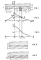
- FIG. 1 schematically illustrates a multilayer structure according to the invention.
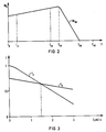
- Figure 2 shows the magnetization characteristic of a material of the control layer and in Figure 3 the temperature gradients are illustrated.
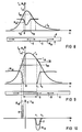
- FIG. 4 shows the temperature profile in the control layer and
- FIG. 5 shows the temperature profile in the storage layer when information is written.
- FIGS. 6 and 7 each illustrate a special embodiment of the multilayer structure with at least one special heat distribution layer.
- FIG. 8 shows the temperature profile of the control layer in a diagram when writing an O signal and
- FIG. 9 shows the temperature profile of this layer when writing an I signal.
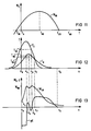
- FIG. 10 shows the charge density and the vertical component of the magnetic field of the control layer in a diagram.
- FIG. 11 shows a magnetization characteristic of the control layer.
- FIG. 1 schematically illustrates a multilayer structure according to the invention.
- Figure 2 shows the magnetization characteristic of a material of the control layer and in Figure 3 the temperature gradients are illustrated.
- FIG. 4 shows the temperature profile in the control layer
- FIG. 5 shows
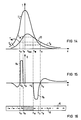
- FIG. 12 shows the temperature profile of the storage layer and in FIG. 13 the magnetization and the charge of the control layer in each case when an O signal is written in and in FIGS. 14 and 15 when an I signal is written in.
- Figure 16 shows the change in magnetization in the control layer.
- FIG. 17 illustrates the magnetization characteristic for a special material of the control layer. A special embodiment with a groove structure is shown in FIG.
- a data storage system contains a multi-layer structure 1 with three layers.
- a storage layer 2 with a thickness of, for example, approximately 70 nm, which can consist, for example, of terbium-iron-cobalt TbFeCo, preferably of ytterbium-terbium-iron-cobalt YbTbFeCo, is for data storage provided.
- the control layer 6 also serves to control the heat diffusion.
- the control layer 6 can preferably consist of samarium-cobalt SmCo or also of terbium-iron-cobalt TbFeCo and of ytterbium-terbium-iron-cobalt YbTbFeCo, the magnetic anisotropy axis 8 of which is indicated by double arrows parallel to the direction of the flat sides and direction the movement v of the storage disk.
- This direction of the easy magnetic axis is obtained in a simple manner by a strong applied magnetic field of, for example, approximately 0.2 T during the production of the control layer 6 by deposition on the storage layer 2.
- the material and thickness of the control layer 6 are essential for determining the temperature gradients and the stabilization of the written information in the storage layer 2.
- the thickness of the control layer 6 is essentially determined by the saturation magnetization. It will generally be at least 200 ⁇ , preferably between 1000 and 2000 ⁇ , and generally not significantly exceed 10000 ⁇ .
- the storage layer 2 is arranged on a substrate 10, which is preferably transparent to a laser beam 12 and can be made of glass, for example.
- the continuously and additionally, for example, step-wise controllable laser beam 12 is predetermined by a radiation source 13 which is generally at rest while the multilayer structure 1 is being moved at the speed v.
- a material can preferably be selected for the control layer 6 whose magnetization characteristic M S6 has a clear gradient difference.
- the characteristic curve has a slight increase up to a predetermined kink temperature T E6 (edge) and then drops steeply after a kink.
- Samarium cobalt SmCo for example, has this property.
- the room temperature T A (ambient) and the temperature T L6 (low) required for writing in an O signal, for example a relatively low temperature are still in the range with an almost constant saturation magnetization M S6 .
- the kink is obtained in the characteristic curve and the saturation magnetization M S drops steeply up to the Curie temperature T c6 .
- the higher temperature T H (high) for writing an I signal in the storage layer 2 lies above the Curie temperature T c6 of the control layer 6.
- FIG. 3 shows a diagram of the temperature T in a predetermined local area of the multilayer structure 1 when writing in information as a function of its distance x from the incident laser beam axis along a data track on a storage disk.
- the temperature T is plotted on a logarithmic scale and in standardized values.
- the temperature gradients are different.
- the temperature gradient of the temperature T2 in the storage layer 2 is, for example, much steeper than the temperature gradient of the temperature T6 in the control layer 6. This has the consequence that after a predetermined time after the laser has been irradiated in the area of cooling, for example, at a distance x of about 1 1/2 to 3 ⁇ m, the temperature T6 in the control layer 6 is higher than the temperature T2 in the storage layer 2.
- the control layer 6 is to be heated to a high temperature T H of, for example, approximately 150 ° C., for example when writing an I signal.
- T H a high temperature
- the heated area is cooled at a distance x 1 to the Curie temperature T c6 of the control layer 6 and at a distance x 3 to the kink temperature T E6 .
- a charge window 20 is formed, the field of which extends to the storage layer 2 and whose vertical component H v6 is effective and impresses the final magnetization distribution in the storage layer 2.
- the course of the temperature T2 of the storage layer 2 is plotted over the distance x from the laser beam 12.
- the storage disk 2 With the movement v of the multilayer structure 1 in the + x direction, the storage disk 2 is cooled in the region of the charge window 20 between x1 and x3 to its critical temperature T Kr2 and at a distance x2 from the incident laser beam 12 the magnetization impressed by the field of the control layer 6 is in the storage layer 2 fixed.
- the control layer is divided into a magnetic layer 5 and a special heat distribution layer 4, which is arranged between the storage layer 2 and the magnetic layer 5.
- Their material and their thickness are chosen so that the heat transfer to the magnetic layer 5 results in a predetermined temperature distribution in this magnetic layer 5. It can preferably consist of selenium Se or a good heat-conducting metal, in particular copper Cu or aluminum Al. Furthermore, aluminum nitride Al3N4 is suitable, for example.
- the magnetic layer 5 consists of a material with high magnetization and a quality factor Q, which can preferably be at least 0.1. Samarium cobalt, for example, is particularly suitable.
- a particularly advantageous further embodiment of the magnetic storage system according to the invention is obtained by providing a heat distribution layer consisting of a double layer between the storage layer 2 and the magnetic layer 5 according to FIG.
- a heat-conducting layer 14 for example made of selenium Se, for the heat diffusion in the vertical direction and for the lateral one
- a distribution layer 15 is provided, which can consist of good heat-conducting and non-magnetic material, preferably of metal, in particular of copper.
- control layer 6 in which the temperature T and the saturation magnetization M s of the control layer 6 are plotted as a function of the distance x from the incident laser beam in a diagram, the control layer 6, for example, down to the temperature T L Heated to 150 ° C.
- the temperature in the cooling area drops in the direction of movement approximately after an e-function.
- the movement v and the lateral heat diffusion result in a somewhat flatter drop in the characteristic in the direction of movement x.
- a charge window results in the distance x01 to x03 from the laser beam.
- the place where the storage layer 2 passes through its critical temperature T Kr2 during cooling is outside of this charge window from x01 to x03.
- the magnetization M s6 changes in accordance with the diagram in FIG. 2 in the charge window.
- the O signal is written in by an external field source, not shown in the figure.
- the control layer 6 for the continuous recording of an I signal, the control layer 6 according to the diagram in FIG. 9, in which the saturation magnetization M s and the temperature T are also plotted over the distance x, is applied by the laser beam 12 via the temperature T E6 and the Curie temperature T c6 heated to the high temperature T H6 .
- the cooling in the direction of movement takes place approximately according to an e-function.
- the magnetization M s6 drops to zero up to the Curie temperature T c6 .
- the magnetization M S6 is zero according to FIG. 2 and then increases during cooling at a distance x 1 to x 3 in the charge window 20 from the Curie temperature T c6 to the temperature temperature T E6 to its maximum value.
- a part of the control layer 6 which is at a temperature T above the Curie temperature T c6 is paramagnetic, which is indicated in FIG. 9 by hatching.
- the magnetization 9 thus changes at the edge of this hatched area compared to the original magnetization 8 in the control layer 6.
- the charge density ⁇ and the vertical component of the magnetic field H v6 are plotted over the distance x from the incident laser beam 12.
- a change in the magnetization M s6 in the temperature range between the temperature T E6 and the Curie temperature T c6 induces a charge ⁇ with a predetermined sign, which results in a corresponding magnetic field
- the vertical component H v6 is indicated by dashed lines in the figure.
- This field component remains irrelevant for the writing of a signal in the memory layer 2.
- the vertical component of the corresponding magnetic field H v6 reaches through to the storage layer 2 and determines the magnetization in this location area of the storage layer, so that a 1 signal can be written.
- a material can be selected for the control layer 6 according to FIG. 11, the compensation temperature T K of which is just below the room temperature T A.
- the magnetizations of the two sub-gratings cancel each other out, the dipoles are all directed towards one another and have the same size.
- the magnetization M S6 increases according to the diagram in FIG. 11, in which the magnetization M S is plotted against the temperature T, up to a maximum value which is reached at the temperature T m6 . Up to the Curie temperature T c6 falls the magnetization then drops again to zero.
- Such a magnetization characteristic has, for example, terbium-iron-cobalt TbFeCo with a predetermined proportion of terbium.
- the magnetization M S6 in the control layer 6 increases from the location x0 to x4 to one Maximum value M 6max at location x4.
- the magnetization characteristic M S6 then has an inflection point and again reaches an inflection point at location x5 and then rises again until it reaches maximum magnetization M 6max again at location x6.
- the magnetization M x6 then drops again.
- has a maximum value during the increase in magnetization from x0 to x4, then goes through zero at x5 and x6 and reaches a large value at the location x7 with reversed polarity.
- This large positive space charge at the location x7 tilts the dipoles in the writable area of the storage layer 2 in a predetermined direction and this dipole distribution is fixed in the storage layer 2, since, according to FIG. 12, the temperature T2 in the storage layer 2 reaches its critical temperature T Kr2 .
- the laser power is increased, for example, to its third stage and thus the storage layer 2 is increased to a temperature T 2 which is substantially higher than the Curie temperature T c6 of the control layer 6 the temperature T6 of the control layer 6 reaches its value T M6 of maximum magnetization and at the location x9 the Curie temperature T c6 of the control layer 6 is exceeded.
- the control layer 6 reaches the Curie temperature T c6 at the location x10 and after the charge window 20 at the location x11 the temperature M6 of maximum magnetization.
- This opposite charge is designated in the control layer 6 according to FIG.
- the critical temperature of the storage layer 2 is passed through and the vertical component of the magnetic field of the control layer 6 in this location range from x10 to x11 determines the direction of the dipoles in the control layer 2nd
- the saturation magnetization M S is plotted against the temperature T for a material of the control layer 6.
- the magnetization characteristic M S6 drops above room temperature T A to Curie temperature T C6 .
- a control layer 6 with this material for example neodymium-iron-cobalt NdFeCo, has a high magnetism at low temperature and a sufficiently large magnetic anisotropy K.
- T Kr critical temperature
- an additional magnetic field source instead of the basic field source or possibly in addition to the basic field source, which generates a magnetic field in the control layer 6 outside the write area parallel to the flat sides of the control layer and at least approximately in the direction of the data tracks.
- This magnetic field counteracts a spread of deviations in the magnetization pattern, in particular of defects.
- the storage layer 2 and the control layer 6 are successively applied to the substrate 10, for example to the surface of the groove provided with corresponding grooves Sputtered substrate 10.
- a material with a positive magnetostriction coefficient ⁇ is preferably selected as the control layer 6.
- a magnetic field can also be applied during the growth of the control layer or also during an additional heat treatment after the coating, which lies in the plate plane and either in the track direction or directed transversely to the data track is.
- two storage layers can also be provided, between which a common control layer is arranged. These layers are expediently applied to a common substrate, for example vapor-deposited or sputtered on.
- This double version of the system has the advantage that the storage density is doubled.
Applications Claiming Priority (2)
| Application Number | Priority Date | Filing Date | Title |
|---|---|---|---|
| DE19883811374 DE3811374A1 (de) | 1988-04-05 | 1988-04-05 | Datenspeichersystem und verfahren zu seiner herstellung |
| DE3811374 | 1988-04-05 |
Publications (2)
| Publication Number | Publication Date |
|---|---|
| EP0336237A2 true EP0336237A2 (fr) | 1989-10-11 |
| EP0336237A3 EP0336237A3 (fr) | 1991-10-30 |
Family
ID=6351396
Family Applications (1)
| Application Number | Title | Priority Date | Filing Date |
|---|---|---|---|
| EP19890105284 Withdrawn EP0336237A3 (fr) | 1988-04-05 | 1989-03-23 | Système d'emmagasinage de données et procédé pour sa fabrication |
Country Status (3)
| Country | Link |
|---|---|
| EP (1) | EP0336237A3 (fr) |
| JP (1) | JPH01307045A (fr) |
| DE (1) | DE3811374A1 (fr) |
Cited By (2)
| Publication number | Priority date | Publication date | Assignee | Title |
|---|---|---|---|---|
| EP0539176A3 (en) * | 1991-10-21 | 1993-06-09 | Sharp Kabushiki Kaisha | Magneto-optical recording method and magneto-optical memory device |
| EP0522840A3 (en) * | 1991-07-08 | 1993-08-18 | Sharp Kabushiki Kaisha | Magneto-optical recording medium |
Families Citing this family (1)
| Publication number | Priority date | Publication date | Assignee | Title |
|---|---|---|---|---|
| JPH056590A (ja) * | 1991-06-28 | 1993-01-14 | Toshiba Corp | 光磁気記録装置 |
Family Cites Families (6)
| Publication number | Priority date | Publication date | Assignee | Title |
|---|---|---|---|---|
| US4126494A (en) * | 1975-10-20 | 1978-11-21 | Kokusai Denshin Denwa Kabushiki Kaisha | Magnetic transfer record film |
| JP2521908B2 (ja) * | 1985-06-11 | 1996-08-07 | 株式会社ニコン | オ―バ―ライト可能な光磁気記録方法、それに使用される光磁気記録装置及び光磁気記録媒体、並びに変調方法、変調装置及び光磁気記録媒体 |
| US4794560A (en) * | 1985-09-30 | 1988-12-27 | International Business Machines Corporation | Eraseable self biasing thermal magneto-optic medium |
| US4649519A (en) * | 1985-09-30 | 1987-03-10 | International Business Machines Corporation | Self biasing thermal magneto-optic medium |
| US4694358A (en) * | 1985-10-28 | 1987-09-15 | Kerdix, Inc. | Magneto-optic recording structure and method |
| DE3752222T2 (de) * | 1986-07-08 | 1999-03-25 | Canon K.K., Tokio/Tokyo | Magnetoptisches Aufzeichnungsmedium mit der Möglichkeit des Überschreibens mit zwei oder mehr Magnetschichten und dieses Medium verwendende Aufzeichnungsmethode |
-
1988
- 1988-04-05 DE DE19883811374 patent/DE3811374A1/de active Granted
-
1989
- 1989-03-23 EP EP19890105284 patent/EP0336237A3/fr not_active Withdrawn
- 1989-04-03 JP JP8562489A patent/JPH01307045A/ja active Pending
Cited By (4)
| Publication number | Priority date | Publication date | Assignee | Title |
|---|---|---|---|---|
| EP0522840A3 (en) * | 1991-07-08 | 1993-08-18 | Sharp Kabushiki Kaisha | Magneto-optical recording medium |
| US5595805A (en) * | 1991-07-08 | 1997-01-21 | Sharp Kabushiki Kaisha | Magneto-optical recording medium |
| EP0539176A3 (en) * | 1991-10-21 | 1993-06-09 | Sharp Kabushiki Kaisha | Magneto-optical recording method and magneto-optical memory device |
| US5402408A (en) * | 1991-10-21 | 1995-03-28 | Sharp Kabushiki Kaisha | Magneto-optical recording method of overwriting without requiring an initialization magnet |
Also Published As
| Publication number | Publication date |
|---|---|
| EP0336237A3 (fr) | 1991-10-30 |
| DE3811374A1 (de) | 1989-10-19 |
| JPH01307045A (ja) | 1989-12-12 |
| DE3811374C2 (fr) | 1992-06-11 |
Similar Documents
| Publication | Publication Date | Title |
|---|---|---|
| DE3889203T2 (de) | Methode zum optischen Abtasten eines Signals aus einem magneto-optischen Speichermedium. | |
| DE3687210T2 (de) | Loeschbares, selbstpolarisiertes, thermisches magnetooptisches medium. | |
| DE3875153T2 (de) | Thermomagnetisches aufzeichnungsverfahren, welches einen energiemodulierten laserstrahl auf eine magnetisch gekoppelte mehrschichtstruktur eines anisotropen magnetfilms anwendet. | |
| DE3888109T2 (de) | Magneto-optisches Aufzeichnungsmedium. | |
| DE68928843T2 (de) | Magnetooptisches speichermedium | |
| DE69111622T2 (de) | Aufzeichnungsmethode für magnetooptisches Speichermedium. | |
| DE3523836C2 (fr) | ||
| DE2911992C2 (de) | Magnetooptisches Speicherelement, Verfahren zu seiner Herstellung und es verwendende Speichervorrichtung | |
| DE69836571T2 (de) | Magnetooptisches Speichermedium und dazugehöriges Wiedergabeverfahren | |
| DE69526532T2 (de) | Magneto-optischer Aufzeichnungsträger und verwendete Informationswiedergabemethode | |
| DE69317719T2 (de) | Magnetooptische Speichervorrichtung und Verfahren zur Informationsaufnahme und -wiedergabe | |
| DE69232052T2 (de) | System und Verfahren zur Wiedergabe von auf einem magnetooptischen Aufzeichungsmedium aufgezeichneten Signalen | |
| DE69421234T2 (de) | Magnetooptisches Aufzeichnungsmedium | |
| DE69026771T2 (de) | Überschreibbare optische Aufzeichnungsmedien | |
| DE69217802T2 (de) | Verfahren zur Aufzeichnung von Information auf und Wiedergabe von Information von einem magnetooptischen Aufzeichnungsmedium | |
| DE3623285A1 (de) | Magnetooptisches aufzeichnungsmedium | |
| DE69119850T2 (de) | Überschreibbares magnetooptisches Aufzeichnungsmedium das einen grösseren Bereich von Strahlungsstärke auf hohem Niveau zulässt | |
| DE69225252T2 (de) | Magneto-optisches Aufzeichnungsmedium | |
| DE3852329T2 (de) | Magneto-optisches Aufzeichnungsmedium und Verfahren. | |
| DE69032931T2 (de) | Magneto-optischer Aufzeichnungsträger | |
| DE69226399T2 (de) | Magneto-optischer Aufzeichnungsträger | |
| DE69027182T2 (de) | Magnetooptischer Aufzeichnungsträger und -gerät | |
| DE3811374C2 (fr) | ||
| DE69223468T2 (de) | Magnetooptisches Aufzeichnungsmedium | |
| DE19507228A1 (de) | Magnetooptisches Aufzeichnungsmedium |
Legal Events
| Date | Code | Title | Description |
|---|---|---|---|
| PUAI | Public reference made under article 153(3) epc to a published international application that has entered the european phase |
Free format text: ORIGINAL CODE: 0009012 |
|
| AK | Designated contracting states |
Kind code of ref document: A2 Designated state(s): DE FR GB IT NL |
|
| 17P | Request for examination filed |
Effective date: 19901205 |
|
| PUAL | Search report despatched |
Free format text: ORIGINAL CODE: 0009013 |
|
| AK | Designated contracting states |
Kind code of ref document: A3 Designated state(s): DE FR GB IT NL |
|
| STAA | Information on the status of an ep patent application or granted ep patent |
Free format text: STATUS: THE APPLICATION IS DEEMED TO BE WITHDRAWN |
|
| 18D | Application deemed to be withdrawn |
Effective date: 19920401 |