EP0336237A2 - Data storage system and process for its manufacture - Google Patents
Data storage system and process for its manufacture Download PDFInfo
- Publication number
- EP0336237A2 EP0336237A2 EP89105284A EP89105284A EP0336237A2 EP 0336237 A2 EP0336237 A2 EP 0336237A2 EP 89105284 A EP89105284 A EP 89105284A EP 89105284 A EP89105284 A EP 89105284A EP 0336237 A2 EP0336237 A2 EP 0336237A2
- Authority
- EP
- European Patent Office
- Prior art keywords
- layer
- data storage
- storage system
- control layer
- magnetization
- Prior art date
- Legal status (The legal status is an assumption and is not a legal conclusion. Google has not performed a legal analysis and makes no representation as to the accuracy of the status listed.)
- Withdrawn
Links
- 238000013500 data storage Methods 0.000 title claims abstract description 41
- 238000004519 manufacturing process Methods 0.000 title claims description 5
- 238000000034 method Methods 0.000 title 1
- 238000003860 storage Methods 0.000 claims abstract description 87
- 230000005415 magnetization Effects 0.000 claims abstract description 74
- 230000005291 magnetic effect Effects 0.000 claims abstract description 46
- 238000009826 distribution Methods 0.000 claims abstract description 22
- 239000000463 material Substances 0.000 claims description 18
- 230000005855 radiation Effects 0.000 claims description 11
- 238000001816 cooling Methods 0.000 claims description 9
- 229910000938 samarium–cobalt magnet Inorganic materials 0.000 claims description 7
- 239000011669 selenium Substances 0.000 claims description 6
- 239000000758 substrate Substances 0.000 claims description 6
- FOPBMNGISYSNED-UHFFFAOYSA-N [Fe].[Co].[Tb] Chemical compound [Fe].[Co].[Tb] FOPBMNGISYSNED-UHFFFAOYSA-N 0.000 claims description 5
- 239000010949 copper Substances 0.000 claims description 5
- KPLQYGBQNPPQGA-UHFFFAOYSA-N cobalt samarium Chemical compound [Co].[Sm] KPLQYGBQNPPQGA-UHFFFAOYSA-N 0.000 claims description 4
- RYGMFSIKBFXOCR-UHFFFAOYSA-N Copper Chemical compound [Cu] RYGMFSIKBFXOCR-UHFFFAOYSA-N 0.000 claims description 3
- BUGBHKTXTAQXES-UHFFFAOYSA-N Selenium Chemical compound [Se] BUGBHKTXTAQXES-UHFFFAOYSA-N 0.000 claims description 3
- 229910052802 copper Inorganic materials 0.000 claims description 3
- 229910052751 metal Inorganic materials 0.000 claims description 3
- 239000002184 metal Substances 0.000 claims description 3
- 229910052711 selenium Inorganic materials 0.000 claims description 3
- PMHQVHHXPFUNSP-UHFFFAOYSA-M copper(1+);methylsulfanylmethane;bromide Chemical compound Br[Cu].CSC PMHQVHHXPFUNSP-UHFFFAOYSA-M 0.000 claims description 2
- 230000005398 magnetoelastic coupling Effects 0.000 claims description 2
- 229910017052 cobalt Inorganic materials 0.000 claims 1
- 239000010941 cobalt Substances 0.000 claims 1
- VABUPYFNWNQKEQ-UHFFFAOYSA-N cobalt dysprosium iron Chemical compound [Fe][Co][Dy] VABUPYFNWNQKEQ-UHFFFAOYSA-N 0.000 claims 1
- 238000010586 diagram Methods 0.000 description 16
- 230000008859 change Effects 0.000 description 5
- 230000008878 coupling Effects 0.000 description 3
- 238000010168 coupling process Methods 0.000 description 3
- 238000005859 coupling reaction Methods 0.000 description 3
- 238000009792 diffusion process Methods 0.000 description 3
- 230000006870 function Effects 0.000 description 3
- 230000005298 paramagnetic effect Effects 0.000 description 3
- 230000010287 polarization Effects 0.000 description 3
- QHMDOPBZEZNSMZ-UHFFFAOYSA-N [Co].[Fe].[Tb].[Yb] Chemical compound [Co].[Fe].[Tb].[Yb] QHMDOPBZEZNSMZ-UHFFFAOYSA-N 0.000 description 2
- 239000011248 coating agent Substances 0.000 description 2
- 238000000576 coating method Methods 0.000 description 2
- 230000000694 effects Effects 0.000 description 2
- 230000012447 hatching Effects 0.000 description 2
- 230000003993 interaction Effects 0.000 description 2
- 230000005374 Kerr effect Effects 0.000 description 1
- 229910052771 Terbium Inorganic materials 0.000 description 1
- KYNBZKPYPKYYBQ-UHFFFAOYSA-N [Co].[Fe].[Nd] Chemical compound [Co].[Fe].[Nd] KYNBZKPYPKYYBQ-UHFFFAOYSA-N 0.000 description 1
- 229910052782 aluminium Inorganic materials 0.000 description 1
- XAGFODPZIPBFFR-UHFFFAOYSA-N aluminium Chemical compound [Al] XAGFODPZIPBFFR-UHFFFAOYSA-N 0.000 description 1
- 230000008901 benefit Effects 0.000 description 1
- 230000015572 biosynthetic process Effects 0.000 description 1
- 230000007423 decrease Effects 0.000 description 1
- 230000007547 defect Effects 0.000 description 1
- 230000008021 deposition Effects 0.000 description 1
- 239000002902 ferrimagnetic material Substances 0.000 description 1
- 239000011521 glass Substances 0.000 description 1
- 238000010438 heat treatment Methods 0.000 description 1
- 230000005381 magnetic domain Effects 0.000 description 1
- 239000000696 magnetic material Substances 0.000 description 1
- 230000005389 magnetism Effects 0.000 description 1
- 230000006641 stabilisation Effects 0.000 description 1
- 238000011105 stabilization Methods 0.000 description 1
- 230000002123 temporal effect Effects 0.000 description 1
- GZCRRIHWUXGPOV-UHFFFAOYSA-N terbium atom Chemical compound [Tb] GZCRRIHWUXGPOV-UHFFFAOYSA-N 0.000 description 1
Images

Classifications
-
- G—PHYSICS
- G11—INFORMATION STORAGE
- G11B—INFORMATION STORAGE BASED ON RELATIVE MOVEMENT BETWEEN RECORD CARRIER AND TRANSDUCER
- G11B11/00—Recording on or reproducing from the same record carrier wherein for these two operations the methods are covered by different main groups of groups G11B3/00 - G11B7/00 or by different subgroups of group G11B9/00; Record carriers therefor
- G11B11/10—Recording on or reproducing from the same record carrier wherein for these two operations the methods are covered by different main groups of groups G11B3/00 - G11B7/00 or by different subgroups of group G11B9/00; Record carriers therefor using recording by magnetic means or other means for magnetisation or demagnetisation of a record carrier, e.g. light induced spin magnetisation; Demagnetisation by thermal or stress means in the presence or not of an orienting magnetic field
- G11B11/105—Recording on or reproducing from the same record carrier wherein for these two operations the methods are covered by different main groups of groups G11B3/00 - G11B7/00 or by different subgroups of group G11B9/00; Record carriers therefor using recording by magnetic means or other means for magnetisation or demagnetisation of a record carrier, e.g. light induced spin magnetisation; Demagnetisation by thermal or stress means in the presence or not of an orienting magnetic field using a beam of light or a magnetic field for recording by change of magnetisation and a beam of light for reproducing, i.e. magneto-optical, e.g. light-induced thermomagnetic recording, spin magnetisation recording, Kerr or Faraday effect reproducing
- G11B11/10502—Recording on or reproducing from the same record carrier wherein for these two operations the methods are covered by different main groups of groups G11B3/00 - G11B7/00 or by different subgroups of group G11B9/00; Record carriers therefor using recording by magnetic means or other means for magnetisation or demagnetisation of a record carrier, e.g. light induced spin magnetisation; Demagnetisation by thermal or stress means in the presence or not of an orienting magnetic field using a beam of light or a magnetic field for recording by change of magnetisation and a beam of light for reproducing, i.e. magneto-optical, e.g. light-induced thermomagnetic recording, spin magnetisation recording, Kerr or Faraday effect reproducing characterised by the transducing operation to be executed
- G11B11/10504—Recording
- G11B11/10506—Recording by modulating only the light beam of the transducer
-
- G—PHYSICS
- G11—INFORMATION STORAGE
- G11B—INFORMATION STORAGE BASED ON RELATIVE MOVEMENT BETWEEN RECORD CARRIER AND TRANSDUCER
- G11B11/00—Recording on or reproducing from the same record carrier wherein for these two operations the methods are covered by different main groups of groups G11B3/00 - G11B7/00 or by different subgroups of group G11B9/00; Record carriers therefor
- G11B11/10—Recording on or reproducing from the same record carrier wherein for these two operations the methods are covered by different main groups of groups G11B3/00 - G11B7/00 or by different subgroups of group G11B9/00; Record carriers therefor using recording by magnetic means or other means for magnetisation or demagnetisation of a record carrier, e.g. light induced spin magnetisation; Demagnetisation by thermal or stress means in the presence or not of an orienting magnetic field
- G11B11/105—Recording on or reproducing from the same record carrier wherein for these two operations the methods are covered by different main groups of groups G11B3/00 - G11B7/00 or by different subgroups of group G11B9/00; Record carriers therefor using recording by magnetic means or other means for magnetisation or demagnetisation of a record carrier, e.g. light induced spin magnetisation; Demagnetisation by thermal or stress means in the presence or not of an orienting magnetic field using a beam of light or a magnetic field for recording by change of magnetisation and a beam of light for reproducing, i.e. magneto-optical, e.g. light-induced thermomagnetic recording, spin magnetisation recording, Kerr or Faraday effect reproducing
- G11B11/10502—Recording on or reproducing from the same record carrier wherein for these two operations the methods are covered by different main groups of groups G11B3/00 - G11B7/00 or by different subgroups of group G11B9/00; Record carriers therefor using recording by magnetic means or other means for magnetisation or demagnetisation of a record carrier, e.g. light induced spin magnetisation; Demagnetisation by thermal or stress means in the presence or not of an orienting magnetic field using a beam of light or a magnetic field for recording by change of magnetisation and a beam of light for reproducing, i.e. magneto-optical, e.g. light-induced thermomagnetic recording, spin magnetisation recording, Kerr or Faraday effect reproducing characterised by the transducing operation to be executed
- G11B11/10517—Overwriting or erasing
- G11B11/10519—Direct overwriting, i.e. performing erasing and recording using the same transducing means
- G11B11/10521—Direct overwriting, i.e. performing erasing and recording using the same transducing means using a single light spot
-
- G—PHYSICS
- G11—INFORMATION STORAGE
- G11B—INFORMATION STORAGE BASED ON RELATIVE MOVEMENT BETWEEN RECORD CARRIER AND TRANSDUCER
- G11B11/00—Recording on or reproducing from the same record carrier wherein for these two operations the methods are covered by different main groups of groups G11B3/00 - G11B7/00 or by different subgroups of group G11B9/00; Record carriers therefor
- G11B11/10—Recording on or reproducing from the same record carrier wherein for these two operations the methods are covered by different main groups of groups G11B3/00 - G11B7/00 or by different subgroups of group G11B9/00; Record carriers therefor using recording by magnetic means or other means for magnetisation or demagnetisation of a record carrier, e.g. light induced spin magnetisation; Demagnetisation by thermal or stress means in the presence or not of an orienting magnetic field
- G11B11/105—Recording on or reproducing from the same record carrier wherein for these two operations the methods are covered by different main groups of groups G11B3/00 - G11B7/00 or by different subgroups of group G11B9/00; Record carriers therefor using recording by magnetic means or other means for magnetisation or demagnetisation of a record carrier, e.g. light induced spin magnetisation; Demagnetisation by thermal or stress means in the presence or not of an orienting magnetic field using a beam of light or a magnetic field for recording by change of magnetisation and a beam of light for reproducing, i.e. magneto-optical, e.g. light-induced thermomagnetic recording, spin magnetisation recording, Kerr or Faraday effect reproducing
- G11B11/10582—Record carriers characterised by the selection of the material or by the structure or form
- G11B11/10586—Record carriers characterised by the selection of the material or by the structure or form characterised by the selection of the material
Definitions
- the invention relates to a data storage system with thermally directly rewritable information, in which the writing, reading and erasing of the information is carried out by means of focusable radiation which can be converted into thermal energy and which can be controlled with intensity in regions with a variable direction of magnetization.
- the storage system includes a multi-layer structure with a magnetic storage layer and a magnetic control layer. This control layer serves as a field source for controlling the magnetization in the storage layer.
- magneto-optical storage systems information with a focused radiation pulse that is converted into heat, preferably a laser beam, can be written into a storage medium whose coercive field strength decreases with increasing temperature.
- the storage medium which is generally designed as a magneto-optical thin layer, has its preferred magnetic axis perpendicular to the flat sides of the storage layer.
- the magneto-optical storage medium becomes the order temperature, the so-called Curie temperature, in predetermined areas, at which a predetermined magnetization can be set by an external magnetic field in the resulting domains.
- the pattern of the magnetization in the domains represents the information stored as binary data.
- a low-intensity laser beam is supplied via a polarizer.
- the polarization of the light beam is rotated by a predetermined angle when the light beam is reflected by the storage layer (Kerr effect) or when it passes through the storage layer (Faraday effect).
- the size of the The angle of rotation is largely determined by the properties of the storage medium.
- the plane of polarization is rotated clockwise or counterclockwise.
- the change in polarization is converted by an analyzer into a change in the intensity of the light beam, which can be registered by a photodetector. By displaying the rotation, the information can be read out of the memory again.
- the written information can be erased with a laser beam during one revolution of the storage disk and new information can be written in during the following revolution.
- a heat beam can be erased and rewritten with the following beam.
- the magnetization for overwriting is only converted in those domains into which new information is to be written.
- the control layer serves to generate a basic magnetic field. It consists of ferrimagnetic material with magnetization that changes depending on the temperature. Reading and overwriting takes place in separate magnetic areas with a two-beam laser system. Both the storage layer and the control layer are heated by the laser beam. If the control layer is heated above its compensation point T K , its direction of magnetization is reversed and at the same time increased. When the Curie temperature T c of the storage layer is reached, this layer becomes writable and its magnetization is parallel to the magnetization in the control layer.
- a known data storage system with thermally directly rewritable information contains a multilayer structure as a data carrier, the storage layer of which is separated from a control layer by an insulating layer which serves to control the temperature in the control layer.
- a laser beam with controllable intensity is used for writing, reading and erasing.
- the control layer generates a magnetic control field and thus a magnetic field orientation in the storage layer as a function of temperature.
- To write an O signal only the storage layer is heated up by a laser beam of short temporal length and the O magnetization is written into the storage layer by, for example, a basic field source arranged above the data carrier.
- To write an I signal the control layer is also heated by a longer laser pulse and the charge pattern in the control layer is changed.
- the changed field profile is transferred to the storage layer.
- the charge pattern of the control layer has only a relatively small magnetizing effect on the storage layer.
- the thickness of the control layer must be chosen to be relatively large so that the dipole character of the charges disappears.
- the materials with this relatively high compensation temperature have a relatively low total magnetization because of the oppositely directed magnetizations in both sub-gratings. Accordingly, only small fields can be generated in the storage layer (European Offenlegungsschrift 0 217 096).
- Another known data storage system in which the information is written, read out and erased by radiation which can be focused and converted into heat energy, contains a multilayer structure with a magnetic storage layer as a data carrier and a control layer for overwriting stored information.
- a laser with controllable intensity is used to write the information.
- the control layer has a perpendicular magnetization and a relatively low coercive force at room temperature.
- a strong initialization field is applied to the control layer at room temperature before recording and ensures magnetization in the same direction.
- a laser beam with pulse modulation is directed onto the multilayer structure and the temperature is increased to such an extent that the magnetization disappears in both layers.
- the invention is based on the object of simplifying and improving this known data storage system, in particular the signal-to-noise ratio is to be increased.
- the invention is based on the knowledge that different temperature gradients in the control layer and the storage layer can be used for writing stable magnetic areas in the storage layer, and it consists in the characterizing features of claim 1.
- the different temperature gradients when writing an I- Signals changed the magnetization in the control layer and generated a charge pattern, whose magnetic field reaches through to the storage layer and controls the dipole orientation in the storage layer. This dipole orientation within the control layer lies in the direction of movement of the multilayer structure in the writing area.
- Radiation with controllable intensity preferably a laser beam, is used, which can additionally be controllable, for example, in three stages. Only a relatively low laser power is required to read out the information. In order to write in a zero signal without previously deleting any information that has already been written in, the laser power is increased to such an extent that the storage layer is heated above its critical temperature T Kr2 and when the location region of the storage layer is cooled with the critical temperature T Kr2 outside the charge window in the Tax layer lies. The O information is written in by an external field at the edge of the writable area where the storage layer cools below the critical temperature T Kr2 .
- the charge window in the control layer is shifted by changing the irradiated laser power in such a way that the location of the memory layer in which the temperature decays below the critical temperature lies in the charge window of the control layer.
- FIG. 1 schematically illustrates a multilayer structure according to the invention.
- Figure 2 shows the magnetization characteristic of a material of the control layer and in Figure 3 the temperature gradients are illustrated.
- FIG. 4 shows the temperature profile in the control layer and
- FIG. 5 shows the temperature profile in the storage layer when information is written.
- FIGS. 6 and 7 each illustrate a special embodiment of the multilayer structure with at least one special heat distribution layer.
- FIG. 8 shows the temperature profile of the control layer in a diagram when writing an O signal and
- FIG. 9 shows the temperature profile of this layer when writing an I signal.
- FIG. 10 shows the charge density and the vertical component of the magnetic field of the control layer in a diagram.
- FIG. 11 shows a magnetization characteristic of the control layer.
- FIG. 1 schematically illustrates a multilayer structure according to the invention.
- Figure 2 shows the magnetization characteristic of a material of the control layer and in Figure 3 the temperature gradients are illustrated.
- FIG. 4 shows the temperature profile in the control layer
- FIG. 5 shows
- FIG. 12 shows the temperature profile of the storage layer and in FIG. 13 the magnetization and the charge of the control layer in each case when an O signal is written in and in FIGS. 14 and 15 when an I signal is written in.
- Figure 16 shows the change in magnetization in the control layer.
- FIG. 17 illustrates the magnetization characteristic for a special material of the control layer. A special embodiment with a groove structure is shown in FIG.
- a data storage system contains a multi-layer structure 1 with three layers.
- a storage layer 2 with a thickness of, for example, approximately 70 nm, which can consist, for example, of terbium-iron-cobalt TbFeCo, preferably of ytterbium-terbium-iron-cobalt YbTbFeCo, is for data storage provided.
- the control layer 6 also serves to control the heat diffusion.
- the control layer 6 can preferably consist of samarium-cobalt SmCo or also of terbium-iron-cobalt TbFeCo and of ytterbium-terbium-iron-cobalt YbTbFeCo, the magnetic anisotropy axis 8 of which is indicated by double arrows parallel to the direction of the flat sides and direction the movement v of the storage disk.
- This direction of the easy magnetic axis is obtained in a simple manner by a strong applied magnetic field of, for example, approximately 0.2 T during the production of the control layer 6 by deposition on the storage layer 2.
- the material and thickness of the control layer 6 are essential for determining the temperature gradients and the stabilization of the written information in the storage layer 2.
- the thickness of the control layer 6 is essentially determined by the saturation magnetization. It will generally be at least 200 ⁇ , preferably between 1000 and 2000 ⁇ , and generally not significantly exceed 10000 ⁇ .
- the storage layer 2 is arranged on a substrate 10, which is preferably transparent to a laser beam 12 and can be made of glass, for example.
- the continuously and additionally, for example, step-wise controllable laser beam 12 is predetermined by a radiation source 13 which is generally at rest while the multilayer structure 1 is being moved at the speed v.
- a material can preferably be selected for the control layer 6 whose magnetization characteristic M S6 has a clear gradient difference.
- the characteristic curve has a slight increase up to a predetermined kink temperature T E6 (edge) and then drops steeply after a kink.
- Samarium cobalt SmCo for example, has this property.
- the room temperature T A (ambient) and the temperature T L6 (low) required for writing in an O signal, for example a relatively low temperature are still in the range with an almost constant saturation magnetization M S6 .
- the kink is obtained in the characteristic curve and the saturation magnetization M S drops steeply up to the Curie temperature T c6 .
- the higher temperature T H (high) for writing an I signal in the storage layer 2 lies above the Curie temperature T c6 of the control layer 6.
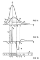
- FIG. 3 shows a diagram of the temperature T in a predetermined local area of the multilayer structure 1 when writing in information as a function of its distance x from the incident laser beam axis along a data track on a storage disk.
- the temperature T is plotted on a logarithmic scale and in standardized values.
- the temperature gradients are different.
- the temperature gradient of the temperature T2 in the storage layer 2 is, for example, much steeper than the temperature gradient of the temperature T6 in the control layer 6. This has the consequence that after a predetermined time after the laser has been irradiated in the area of cooling, for example, at a distance x of about 1 1/2 to 3 ⁇ m, the temperature T6 in the control layer 6 is higher than the temperature T2 in the storage layer 2.
- the control layer 6 is to be heated to a high temperature T H of, for example, approximately 150 ° C., for example when writing an I signal.
- T H a high temperature
- the heated area is cooled at a distance x 1 to the Curie temperature T c6 of the control layer 6 and at a distance x 3 to the kink temperature T E6 .
- a charge window 20 is formed, the field of which extends to the storage layer 2 and whose vertical component H v6 is effective and impresses the final magnetization distribution in the storage layer 2.
- the course of the temperature T2 of the storage layer 2 is plotted over the distance x from the laser beam 12.
- the storage disk 2 With the movement v of the multilayer structure 1 in the + x direction, the storage disk 2 is cooled in the region of the charge window 20 between x1 and x3 to its critical temperature T Kr2 and at a distance x2 from the incident laser beam 12 the magnetization impressed by the field of the control layer 6 is in the storage layer 2 fixed.
- the control layer is divided into a magnetic layer 5 and a special heat distribution layer 4, which is arranged between the storage layer 2 and the magnetic layer 5.
- Their material and their thickness are chosen so that the heat transfer to the magnetic layer 5 results in a predetermined temperature distribution in this magnetic layer 5. It can preferably consist of selenium Se or a good heat-conducting metal, in particular copper Cu or aluminum Al. Furthermore, aluminum nitride Al3N4 is suitable, for example.
- the magnetic layer 5 consists of a material with high magnetization and a quality factor Q, which can preferably be at least 0.1. Samarium cobalt, for example, is particularly suitable.
- a particularly advantageous further embodiment of the magnetic storage system according to the invention is obtained by providing a heat distribution layer consisting of a double layer between the storage layer 2 and the magnetic layer 5 according to FIG.
- a heat-conducting layer 14 for example made of selenium Se, for the heat diffusion in the vertical direction and for the lateral one
- a distribution layer 15 is provided, which can consist of good heat-conducting and non-magnetic material, preferably of metal, in particular of copper.
- control layer 6 in which the temperature T and the saturation magnetization M s of the control layer 6 are plotted as a function of the distance x from the incident laser beam in a diagram, the control layer 6, for example, down to the temperature T L Heated to 150 ° C.
- the temperature in the cooling area drops in the direction of movement approximately after an e-function.
- the movement v and the lateral heat diffusion result in a somewhat flatter drop in the characteristic in the direction of movement x.
- a charge window results in the distance x01 to x03 from the laser beam.
- the place where the storage layer 2 passes through its critical temperature T Kr2 during cooling is outside of this charge window from x01 to x03.
- the magnetization M s6 changes in accordance with the diagram in FIG. 2 in the charge window.
- the O signal is written in by an external field source, not shown in the figure.
- the control layer 6 for the continuous recording of an I signal, the control layer 6 according to the diagram in FIG. 9, in which the saturation magnetization M s and the temperature T are also plotted over the distance x, is applied by the laser beam 12 via the temperature T E6 and the Curie temperature T c6 heated to the high temperature T H6 .
- the cooling in the direction of movement takes place approximately according to an e-function.
- the magnetization M s6 drops to zero up to the Curie temperature T c6 .
- the magnetization M S6 is zero according to FIG. 2 and then increases during cooling at a distance x 1 to x 3 in the charge window 20 from the Curie temperature T c6 to the temperature temperature T E6 to its maximum value.
- a part of the control layer 6 which is at a temperature T above the Curie temperature T c6 is paramagnetic, which is indicated in FIG. 9 by hatching.
- the magnetization 9 thus changes at the edge of this hatched area compared to the original magnetization 8 in the control layer 6.
- the charge density ⁇ and the vertical component of the magnetic field H v6 are plotted over the distance x from the incident laser beam 12.
- a change in the magnetization M s6 in the temperature range between the temperature T E6 and the Curie temperature T c6 induces a charge ⁇ with a predetermined sign, which results in a corresponding magnetic field
- the vertical component H v6 is indicated by dashed lines in the figure.
- This field component remains irrelevant for the writing of a signal in the memory layer 2.
- the vertical component of the corresponding magnetic field H v6 reaches through to the storage layer 2 and determines the magnetization in this location area of the storage layer, so that a 1 signal can be written.
- a material can be selected for the control layer 6 according to FIG. 11, the compensation temperature T K of which is just below the room temperature T A.
- the magnetizations of the two sub-gratings cancel each other out, the dipoles are all directed towards one another and have the same size.
- the magnetization M S6 increases according to the diagram in FIG. 11, in which the magnetization M S is plotted against the temperature T, up to a maximum value which is reached at the temperature T m6 . Up to the Curie temperature T c6 falls the magnetization then drops again to zero.
- Such a magnetization characteristic has, for example, terbium-iron-cobalt TbFeCo with a predetermined proportion of terbium.
- the magnetization M S6 in the control layer 6 increases from the location x0 to x4 to one Maximum value M 6max at location x4.
- the magnetization characteristic M S6 then has an inflection point and again reaches an inflection point at location x5 and then rises again until it reaches maximum magnetization M 6max again at location x6.
- the magnetization M x6 then drops again.
- has a maximum value during the increase in magnetization from x0 to x4, then goes through zero at x5 and x6 and reaches a large value at the location x7 with reversed polarity.
- This large positive space charge at the location x7 tilts the dipoles in the writable area of the storage layer 2 in a predetermined direction and this dipole distribution is fixed in the storage layer 2, since, according to FIG. 12, the temperature T2 in the storage layer 2 reaches its critical temperature T Kr2 .
- the laser power is increased, for example, to its third stage and thus the storage layer 2 is increased to a temperature T 2 which is substantially higher than the Curie temperature T c6 of the control layer 6 the temperature T6 of the control layer 6 reaches its value T M6 of maximum magnetization and at the location x9 the Curie temperature T c6 of the control layer 6 is exceeded.
- the control layer 6 reaches the Curie temperature T c6 at the location x10 and after the charge window 20 at the location x11 the temperature M6 of maximum magnetization.
- This opposite charge is designated in the control layer 6 according to FIG.
- the critical temperature of the storage layer 2 is passed through and the vertical component of the magnetic field of the control layer 6 in this location range from x10 to x11 determines the direction of the dipoles in the control layer 2nd
- the saturation magnetization M S is plotted against the temperature T for a material of the control layer 6.
- the magnetization characteristic M S6 drops above room temperature T A to Curie temperature T C6 .
- a control layer 6 with this material for example neodymium-iron-cobalt NdFeCo, has a high magnetism at low temperature and a sufficiently large magnetic anisotropy K.
- T Kr critical temperature
- an additional magnetic field source instead of the basic field source or possibly in addition to the basic field source, which generates a magnetic field in the control layer 6 outside the write area parallel to the flat sides of the control layer and at least approximately in the direction of the data tracks.
- This magnetic field counteracts a spread of deviations in the magnetization pattern, in particular of defects.
- the storage layer 2 and the control layer 6 are successively applied to the substrate 10, for example to the surface of the groove provided with corresponding grooves Sputtered substrate 10.
- a material with a positive magnetostriction coefficient ⁇ is preferably selected as the control layer 6.
- a magnetic field can also be applied during the growth of the control layer or also during an additional heat treatment after the coating, which lies in the plate plane and either in the track direction or directed transversely to the data track is.
- two storage layers can also be provided, between which a common control layer is arranged. These layers are expediently applied to a common substrate, for example vapor-deposited or sputtered on.
- This double version of the system has the advantage that the storage density is doubled.
Abstract
Das Datenspeichersystem mit thermisch direkt überschreibbarer Information ist mit einer Mehrschichtstruktur versehen, die eine Speicherschicht und eine Steuerschicht zur Magnetisierung der Speicherschicht enthält. Erfindungsgemäß ist mindestens eine Steuerschicht (6) mit von der Speicherschicht (2) abweichender Wärmeleitung vorgesehen, deren Magnetisierung parallel zu ihren Flachseiten in der Bewegungsrichtung v der Mehrschichtstruktur (1) verläuft. Die Speicherschicht (2) hat ein oder mehrere Untergitter mit vorbestimmter Dipolverteilung, deren Richtung durch das Magnetfeld der Steuerschicht (6) veränderbar ist. In dieser Ausführungsform erhält man ein Datenspeichersystem mit hohem Signal-Rauschverhältnis und direkt überschreibbarer Information. 
Description
Die Erfindung bezieht sich auf ein Datenspeichersystem mit thermisch direkt überschreibbarer Information, bei dem das Einschreiben, Auslesen und Löschen der Information durch fokussierbare und in Wärmeenergie umwandelbare Strahlung mit steuerbarer Intensität in Bereichen mit veränderbarer Magnetisierungsrichtung erfolgt. Das Speichersystem enthält eine Mehrschichtstruktur mit einer magnetischen Speicherschicht und einer magnetischen Steuerschicht. Diese Steuerschicht dient als Feldquelle für die Steuerung der Magnetisierung in der Speicherschicht.The invention relates to a data storage system with thermally directly rewritable information, in which the writing, reading and erasing of the information is carried out by means of focusable radiation which can be converted into thermal energy and which can be controlled with intensity in regions with a variable direction of magnetization. The storage system includes a multi-layer structure with a magnetic storage layer and a magnetic control layer. This control layer serves as a field source for controlling the magnetization in the storage layer.
In magnetooptischen Speichersystemen kann bekanntlich eine Information mit einem fokussierten Strahlungsimpuls, der in Wärme umgesetzt wird, vorzugsweise einem Laserstrahl, in ein Speichermedium eingeschrieben werden, dessen Koerzitivfeldstärke mit steigender Temperatur abnimmt. Das im allgemeinen als magnetooptische Dünnschicht gestaltete Speichermedium hat seine bevorzugte magnetische Achse senkrecht zu den Flachseiten der Speicherschicht. Durch den fokussierten Laserstrahl wird das magnetooptische Speichermedium in vorbestimmten Bereichen etwa die Ordnungstemperatur, die sogenannte Curie-Temperatur, bei der eine vorbestimmte Magnetisierung durch ein äußeres Magnetfeld in den entstehenden Domänen eingestellt werden kann. Das Muster der Magnetisierung in den Domänen stellt die als binäre Daten gespeicherte Information dar. Zum Auslesen der Daten wird ein Laserstrahl geringer Intensität über einen Polarisator zugeführt. Die Polarisation des Lichtstrahls wird um einen vorbestimmten Winkel gedreht, wenn der Lichtstrahl von der Speicherschicht reflektiert wird (Kerr-Effekt) oder wenn er durch die Speicherschicht hindurchtritt (Faraday-Effekt). Die Größe des Drehwinkels wird wesentlich bestimmt durch die Eigenschaften des Speichermediums. In Abhängigkeit von der Magnetisierungsrichtung in den Domänen wird die Polarisationsebene im Uhrzeigersinn oder gegen den Uhrzeigersinn gedreht. Durch einen Analysator wird die Änderung der Polarisation umgewandelt in eine Änderung der Intensität des Lichtstrahls, die von einem Photodetektor registriert werden kann. Durch Anzeige der Drehung kann die Information aus dem Speicher wieder ausgelesen werden.As is known, in magneto-optical storage systems, information with a focused radiation pulse that is converted into heat, preferably a laser beam, can be written into a storage medium whose coercive field strength decreases with increasing temperature. The storage medium, which is generally designed as a magneto-optical thin layer, has its preferred magnetic axis perpendicular to the flat sides of the storage layer. By means of the focused laser beam, the magneto-optical storage medium becomes the order temperature, the so-called Curie temperature, in predetermined areas, at which a predetermined magnetization can be set by an external magnetic field in the resulting domains. The pattern of the magnetization in the domains represents the information stored as binary data. To read out the data, a low-intensity laser beam is supplied via a polarizer. The polarization of the light beam is rotated by a predetermined angle when the light beam is reflected by the storage layer (Kerr effect) or when it passes through the storage layer (Faraday effect). The size of the The angle of rotation is largely determined by the properties of the storage medium. Depending on the direction of magnetization in the domains, the plane of polarization is rotated clockwise or counterclockwise. The change in polarization is converted by an analyzer into a change in the intensity of the light beam, which can be registered by a photodetector. By displaying the rotation, the information can be read out of the memory again.
Zum Überschreiben einer eingeschriebenen Information kann beispielsweise während einer Umdrehung der Speicherplatte die eingeschriebene Information mit einem Laserstrahl gelöscht und während der folgenden Umdrehung eine neue Information eingeschrieben werden. Ferner kann in einem Zweistrahlsystem mit einem Wärmestrahl gelöscht und mit dem nachfolgenden Strahl neu eingeschrieben werden.To overwrite written information, for example, the written information can be erased with a laser beam during one revolution of the storage disk and new information can be written in during the following revolution. Furthermore, in a two-beam system, a heat beam can be erased and rewritten with the following beam.
Bei einem weiteren bekannten Datenspeichersystem mit einer Speicherschicht, einem Dielektrikum und einer Steuerschicht wird zum Überschreiben die Magnetisierung nur in denjenigen Domänen umgewandelt, in die eine neue Information eingeschrieben werden soll. Die Steuerschicht dient zum Erzeugen eines magnetischen Grundfeldes. Sie besteht aus ferrimagnetischem Material mit in Abhängigkeit von der Temperatur wechselnder Magnetisierung. Lesen und Überschreiben erfolgt in getrennten magnetischen Bereichen mit einem Zweistrahl-Lasersystem. Durch den Laserstrahl werden sowohl die Speicherschicht als auch die Steuerschicht erwärmt. Wird die Steuerschicht über ihren Kompensationspunkt TK erwärmt, so wird ihre Magnetisierungsrichtung umgedreht und zugleich erhöht. Beim Erreichen der Curie-Temperatur Tc der Speicherschicht wird diese Schicht schreibfähig und ihre Magnetisierung stellt sich parallel zur Magnetisierung in der Steuerschicht. Beim Abkühlen wird unterhalb der Kompensationstemperatur TK der Steuerschicht die Magnetisierung umgedreht und ist dann der Magnetisierung in der Spei cherschicht entgegengerichtet. Die Magnetisierung in der Steuerschicht wird umgewandelt durch magnetostatische Wechselwirkung. Die Koerzitivfeldstärken der beiden Schichten müssen somit aufeinander abgestimmt sein, damit die Magnetisierung in der Steuerschicht durch magnetostatische Wechselwirkung umgedreht werden kann, während die Magnetisierung in der Speicherschicht unverändert bleibt (US-PS 4 649 519).In a further known data storage system with a storage layer, a dielectric and a control layer, the magnetization for overwriting is only converted in those domains into which new information is to be written. The control layer serves to generate a basic magnetic field. It consists of ferrimagnetic material with magnetization that changes depending on the temperature. Reading and overwriting takes place in separate magnetic areas with a two-beam laser system. Both the storage layer and the control layer are heated by the laser beam. If the control layer is heated above its compensation point T K , its direction of magnetization is reversed and at the same time increased. When the Curie temperature T c of the storage layer is reached, this layer becomes writable and its magnetization is parallel to the magnetization in the control layer. When cooling below the compensation temperature T K of the control layer, the magnetization is reversed and the magnetization is then in the memory Layer opposed. The magnetization in the control layer is converted by magnetostatic interaction. The coercive field strengths of the two layers must therefore be matched to one another so that the magnetization in the control layer can be reversed by magnetostatic interaction, while the magnetization in the storage layer remains unchanged (US Pat. No. 4,649,519).
Ein bekanntes Datenspeichersystem mit thermisch direkt überschreibbarer Information enthält eine Mehrschichtstruktur als Datenträger, dessen Speicherschicht von einer Steuerschicht durch eine Isolierschicht getrennt ist, die zur Steuerung der Temperatur in der Steuerschicht dient. Zum Einschreiben, Auslesen und Löschen dient ein Laserstrahl mit steuerbarer Intensität. Die Steuerschicht erzeugt ein magnetisches Steuerfeld und damit eine magnetische Feldorientierung in der Speicherschicht als Funktion der Temperatur. Zum Einschreiben eines O-Signals wird durch einen Laserstrahl geringer zeitlicher Länge nur die Speicherschicht aufgeheizt und durch zum Beispiel eine über dem Datenträger angeordnete Grundfeldquelle die O-Magnetisierung in die Speicherschicht eingeschrieben. Zum Einschreiben eines I-Signals wird durch einen längeren Laserimpuls auch die Steuerschicht aufgeheizt und das Ladungsmuster in der Steuerschicht geändert. Der geänderte Feldverlauf wird auf die Speicherschicht übertragen. In dieser Ausführungsform hat jedoch aus Ladungsmuster der Steuerschicht nur eine verhältnismäßig geringe magnetisierende Wirkung auf die Speicherschicht. Die Dicke der Steuerschicht muß verhältnismäßig groß gewählt werden, damit der Dipol-Charakter der Ladungen verschwindet. Außerdem besitzen die Materialien mit dieser relativ hohen Kompensationstemperatur wegen der entgegengesetzt gerichteten Magnetisierungen in beiden Untergittern eine relativ niedrige Gesamtmagnetisierung. Dementsprechend können nur kleine Felder in der Speicherschicht erzeugt werden (Europäische Offenlegungsschrift 0 217 096).A known data storage system with thermally directly rewritable information contains a multilayer structure as a data carrier, the storage layer of which is separated from a control layer by an insulating layer which serves to control the temperature in the control layer. A laser beam with controllable intensity is used for writing, reading and erasing. The control layer generates a magnetic control field and thus a magnetic field orientation in the storage layer as a function of temperature. To write an O signal, only the storage layer is heated up by a laser beam of short temporal length and the O magnetization is written into the storage layer by, for example, a basic field source arranged above the data carrier. To write an I signal, the control layer is also heated by a longer laser pulse and the charge pattern in the control layer is changed. The changed field profile is transferred to the storage layer. In this embodiment, however, the charge pattern of the control layer has only a relatively small magnetizing effect on the storage layer. The thickness of the control layer must be chosen to be relatively large so that the dipole character of the charges disappears. In addition, the materials with this relatively high compensation temperature have a relatively low total magnetization because of the oppositely directed magnetizations in both sub-gratings. Accordingly, only small fields can be generated in the storage layer (European Offenlegungsschrift 0 217 096).
Ein weiteres bekanntes Datenspeichersystem, bei dem das Einschreiben, Auslesen und Löschen der Information durch fokussierbare und in Wärmeenergie umwandelbare Strahlung erfolgt, enthält eine Mehrschichtstruktur mit einer magnetischen Speicherschicht als Datenträger und einer Steuerschicht zum Überschreiben einer gespeicherten Information. Zum Einschreiben der Information dient ein Laser mit steuerbarer Intensität. Die Steuerschicht hat eine senkrecht Magnetisierung und eine relativ geringe Koerzitivfeldstärke bei Raumtemperatur. Ein starkes Initialisierungsfeld wird vor der Aufzeichnung bei Raumtemperatur an die Steuerschicht angelegt und sorgt für eine Magnetisierung in gleicher Richtung. Zum Überschreiben wird ein Laserstrahl mit Impulsmodulation auf die Mehrschichtstruktur gerichtet und die Temperatur so weit erhöht, daß die Magnetisierung in beiden Schichten verschwindet. Damit wird ein Bit in die Steuerschicht eingeschrieben und bei der Abkühlung durch magnetische Austauschkopplung oder magnetostatische Kopplung auf die Speicherschicht übertragen. Mit einem niedrigen Pegel des Laserstrahls, mit dem die Mehrschichtstruktur nur unterhalb der Curie-Temperatur der Steuerschicht erwärmt wird, bleibt die Magnetisierung der Steuerschicht unverändert und in die Speicherschicht wird ein anderes Bit eingeschrieben werden. Die Initialisierung und Einschreibung erfolgt in getrennten Bereichen. Im Initialisierungsbereich der Steuerschicht wird die Information wieder gelöscht, damit sie im Schreibbereich wieder neu eingeschrieben werden kann. In dieser Ausführungsform des Datenspeichersystems ist ein Initialiserungsfeld erforderlich, das in der Steuerschicht die eingeschriebenen Daten löscht und zugleich die Daten in der Speicherschicht nicht verändert. Die eingeschriebenen magnetischen Domänen sind stabil durch magnetische Wandreibung (wall friction). Man braucht deshalb als Speicherschicht ein Material mit hoher Koerzitivfeldstärke, damit ein Wandkriechen vermieden werden kann und zugleich müssen hohe Ansprüche an die Homogenität der Speicherschicht und die Gerätetemperatur gestellt werden (DE-OS 36 19 618).Another known data storage system, in which the information is written, read out and erased by radiation which can be focused and converted into heat energy, contains a multilayer structure with a magnetic storage layer as a data carrier and a control layer for overwriting stored information. A laser with controllable intensity is used to write the information. The control layer has a perpendicular magnetization and a relatively low coercive force at room temperature. A strong initialization field is applied to the control layer at room temperature before recording and ensures magnetization in the same direction. To overwrite it, a laser beam with pulse modulation is directed onto the multilayer structure and the temperature is increased to such an extent that the magnetization disappears in both layers. In this way, a bit is written into the control layer and is transferred to the storage layer during cooling by magnetic exchange coupling or magnetostatic coupling. With a low level of the laser beam, with which the multilayer structure is only heated below the Curie temperature of the control layer, the magnetization of the control layer remains unchanged and another bit is written into the storage layer. Initialization and enrollment take place in separate areas. The information is deleted in the initialization area of the control layer so that it can be rewritten in the write area. In this embodiment of the data storage system, an initialization field is required which deletes the data written in the control layer and at the same time does not change the data in the storage layer. The registered magnetic domains are stable due to magnetic wall friction. A material with a high coercive field strength is therefore required as the storage layer so that creeping can be avoided and at the same time high demands must be placed on the homogeneity of the storage layer and the device temperature (DE-OS 36 19 618).
Der Erfindung liegt nun die Aufgabe zugrunde, dieses bekannte Datenspeichersystem zu vereinfachen und zu verbessern, insbesondere soll das Signal-Rauschverhältnis erhöht werden.The invention is based on the object of simplifying and improving this known data storage system, in particular the signal-to-noise ratio is to be increased.
Die Erfindung beruht nun auf der Erkenntnis, daß zum Einschreiben stabiler magnetischer Bereiche in der Speicherschicht unterschiedliche Temperaturgradienten in der Steuerschicht und der Speicherschicht herangezogen werden können, und sie besteht in den kennzeichnenden Merkmalen des Anspruchs 1. Durch die unterschiedlichen Temperaturgradienten wird beim Einschreiben eines I-Signals die Magnetisierung in der Steuerschicht geändert und ein Ladungsmuster erzeugt, dessen magnetisches Feld zur Speicherschicht durchgreift und die Dipolorientierung in der Speicherschicht steuert. Diese Dipolorientierung innerhalb der Steuerschicht liegt in der Bewegungsrichtung der Mehrschichtstruktur im Schreibbereich.The invention is based on the knowledge that different temperature gradients in the control layer and the storage layer can be used for writing stable magnetic areas in the storage layer, and it consists in the characterizing features of
Es wird eine Strahlung mit steuerbarer Intensität, vorzugsweise ein Laserstrahl, verwendet, der zusätzlich beispielsweise in drei Stufen steuerbar sein kann. Zum Auslesen der Information ist nur eine verhältnismäßig geringe Laserleistung erforderlich. Zum Einschreiben eines Null-Signals ohne vorheriges Löschen einer gegebenenfalls bereits eingeschriebenen Information wird die Laserleistung so weit erhöht, daß die Speicherschicht oberhalb ihrer kritischen Temperatur TKr2 erwärmt wird und beim Abkühlen der Ortsbereich der Speicherschicht mit der kritischen Temperatur TKr2 außerhalb des Ladungsfensters in der Steuerschicht liegt. Die O-Information wird am Rande des schreibfähigen Bereiches, wo die Speicherschicht unter die kritische Temperatur TKr2 abkühlt, durch ein äußeres Feld eingeschrieben.Radiation with controllable intensity, preferably a laser beam, is used, which can additionally be controllable, for example, in three stages. Only a relatively low laser power is required to read out the information. In order to write in a zero signal without previously deleting any information that has already been written in, the laser power is increased to such an extent that the storage layer is heated above its critical temperature T Kr2 and when the location region of the storage layer is cooled with the critical temperature T Kr2 outside the charge window in the Tax layer lies. The O information is written in by an external field at the edge of the writable area where the storage layer cools below the critical temperature T Kr2 .
Beim Einschreiben eines I-Signals wird durch eine Änderung der eingestrahlten Laserleistung das Ladungsfenster in der Steuerschicht derart verschoben, daß der Ortsbereich der Speicher schicht, in dem die Temperatur unter die kritische Temperatur abklingt, im Ladungsfenster der Steuerschicht liegt.When an I signal is written in, the charge window in the control layer is shifted by changing the irradiated laser power in such a way that the location of the memory layer in which the temperature decays below the critical temperature lies in the charge window of the control layer.
Zur weiteren Erläuterung der Erfindung wird auf die Zeichnung Bezug genommen, in deren Figur 1 eine Mehrschichtstruktur gemäß der Erfindung schematisch veranschaulicht ist. Figur 2 zeigt die Magnetisierungskennlinie eines Materials der Steuerschicht und in Figur 3 sind die Temperaturgradienten veranschaulicht. In Figur 4 ist der Temperaturverlauf in der Steuerschicht und in Figur 5 der Temperaturverlauf in der Speicherschicht beim Einschreiben einer Information dargestellt. In den Figuren 6 und 7 ist jeweils eine besondere Ausführungsform der Mehrschichtstruktur mit wenigstens einer besonderen Wärmeverteilungsschicht veranschaulicht. Figur 8 zeigt den Temperaturverlauf der Steuerschicht in einem Diagramm beim Einschreiben eines O-Signals und Figur 9 den Temperaturverlauf dieser Schicht beim Einschreiben eines I-Signals. In Figur 10 sind die Ladungsdichte und die vertikale Komponente des Magnetfeldes der Steuerschicht in einem Diagramm dargestellt. Figur 11 zeigt eine Magnetisierungskennlinie der Steuerschicht. In Figur 12 ist der Temperaturverlauf der Speicherschicht und in Figur 13 die Magnetisierung und die Ladung der Steuerschicht jeweils beim Einschreiben eines O-Signals und in den Figuren 14 und 15 beim Einschreiben eines I-Signals veranschaulicht. Figur 16 zeigt die Änderung der Magnetisierung in der Steuerschicht. In Figur 17 ist die Magnetisierungskennlinie für ein besonderes Material der Steuerschicht veranschaulicht. Eine besondere Ausführungsform mit einer Rillenstruktur ist in Figur 18 dargestellt.To further explain the invention, reference is made to the drawing, in which FIG. 1 schematically illustrates a multilayer structure according to the invention. Figure 2 shows the magnetization characteristic of a material of the control layer and in Figure 3 the temperature gradients are illustrated. FIG. 4 shows the temperature profile in the control layer and FIG. 5 shows the temperature profile in the storage layer when information is written. FIGS. 6 and 7 each illustrate a special embodiment of the multilayer structure with at least one special heat distribution layer. FIG. 8 shows the temperature profile of the control layer in a diagram when writing an O signal and FIG. 9 shows the temperature profile of this layer when writing an I signal. FIG. 10 shows the charge density and the vertical component of the magnetic field of the control layer in a diagram. FIG. 11 shows a magnetization characteristic of the control layer. FIG. 12 shows the temperature profile of the storage layer and in FIG. 13 the magnetization and the charge of the control layer in each case when an O signal is written in and in FIGS. 14 and 15 when an I signal is written in. Figure 16 shows the change in magnetization in the control layer. FIG. 17 illustrates the magnetization characteristic for a special material of the control layer. A special embodiment with a groove structure is shown in FIG.
Gemäß Figur 1 enthält ein Datenspeichersystem eine Mehrschichtstruktur 1 mit drei Schichten. Eine Speicherschicht 2 mit einer Dicke von beispielsweise etwa 70 nm, die beispielsweise aus Terbium-Eisen-Kobalt TbFeCo, vorzugsweise aus Ytterbium-Terbium-Eisen-Kobalt YbTbFeCo, bestehen kann, ist zur Datenspei cherung vorgesehen. Die Steuerschicht 6 dient zugleich zur Steuerung der Wärmediffusion. Die Steuerschicht 6 kann vorzugsweise aus Samarium-Kobalt SmCo oder auch aus Terbium-Eisen-Kobalt TbFeCo sowie aus Ytterbium-Terbium-Eisen-Kobalt YbTbFeCo bestehen, dessen magnetische Anisotropie-Achse 8 in der durch Doppelpfeile angedeuteten beidseitigen parallel zur Richtung der Flachseiten und Richtung der Bewegung v der Speicherplatte verläuft. Diese Richtung der leichten magnetischen Achse erhält man in einfacher Weise durch ein starkes angelegtes magnetisches Feld von beispielsweise etwa 0,2 T bei der Herstellung der Steuerschicht 6 durch Abscheidung auf der Speicherschicht 2. Material und Dicke der Steuerschicht 6 sind wesentlich für die Bestimmung der Temperaturgradienten und die Stabilisierung der eingeschriebenen Information in der Speicherschicht 2. Ein großes Magnetfeld erhält man mit einer verhältnismäßig großen Dicke der Steuerschicht. Die Dicke der Steuerschicht 6 wird wesentlich bestimmt durch die Sättigungsmagnetisierung. Sie wird im allgemeinen wenigstens 200 Å betragen, vorzugsweise zwischen 1000 und 2000 Å gewählt und im allgemeinen 10000 Å nicht wesentlich überschreiten. Die Speicherschicht 2 ist auf einem Substrat 10 angeordnet, das vorzugsweise für einen Laserstrahl 12 durchlässig ist und beispielsweise aus Glas bestehen kann. Der kontinuierlich und zusätzlich beispielsweise stufenweise steuerbare Laserstrahl 12 wird von einer Strahlungsquelle 13 vorgegeben, die im allgemeinen ruht, während die Mehrschichtstruktur 1 mit der Geschwindigkeit v bewegt wird.According to FIG. 1, a data storage system contains a
Gemäß dem Diagramm der Figur 2, in dem die Sättigungsmagnetisierung MS der Steuerschicht 6 über der Temperatur T aufgetragen ist, kann für die Steuerschicht 6 vorzugsweise ein Material gewählt werden, dessen Magnetisierungskennlinie MS6 einen deutlichen Steigungsunterschied hat. Bis zu einer vorbestimmten Knicktemperatur TE6 (edge) verläuft die Kennlinie mit einem geringen Anstieg und fällt dann nach einem Knick steil ab. Diese Eigenschaft hat beispielsweise Samarium-Kobalt SmCo. In der Magnetisierungskennlinie MS6 liegen die Raumtemperatur TA (ambient) und die zum Einschreiben eines O-Signals erforderliche, beispielsweise verhältnismäßig tiefe Temperatur TL6 (low) noch im Bereich mit nahezu konstanter Sättigungsmagnetisierung MS6. Bei der Knicktemperatur TE6 erhält man den Knick in der Kennlinie und die Sättigungsmagnetisierung MS fällt steil ab bis zur Curie-Temperatur Tc6. Die höhere Temperatur TH (high) zum Einschreiben eines I-Signals in der Speicherschicht 2 liegt oberhalb der Curie-Temperatur Tc6 der Steuerschicht 6.According to the diagram in FIG. 2, in which the saturation magnetization M S of the
In Figur 3 ist die Temperatur T in einem vorbestimmten örtlichen Bereich der Mehrschichtstruktur 1 beim Einschreiben einer Information in Abhängigkeit von ihrem Abstand x von der auftreffenden Laserstrahlachse entlang einer Datenspur auf einer Speicherplatte in einem Diagramm veranschaulicht. Die Temperatur T ist in logarithmischem Maßstab und in normierten Werten aufgetragen. Die Temperaturgradienten sind unterschiedlich. Der Temperaturgradient der Temperatur T₂ in der Speicherschicht 2 ist beispielsweise wesentlich steiler als der Temperaturgradient der Temperatur T₆ in der Steuerschicht 6. Dies hat zur Folge, daß nach Ablauf einer vorbestimmten Zeit nach dem Einstrahlen des Lasers im Bereich der Abkühlung beispielsweise im Abstand x von etwa 1 1/2 bis 3 µm die Temperatur T₆ in der Steuerschicht 6 höher ist als die Temperatur T₂ in der Speicherschicht 2.FIG. 3 shows a diagram of the temperature T in a predetermined local area of the
Im Diagramm der Figur 4 ist der Temperaturverlauf T₆ in der Steuerschicht 6 über dem Abstand x vom auftreffenden Laserstrahl 12 einer Strahlungsquelle 14 an der Stelle x = 0 aufgetragen. Die Steuerschicht 6 soll beispielsweise beim Einschreiben eines I-Signals auf eine hohe Temperatur TH von beispielsweise etwa 150°C erwärmt werden. Mit der Bewegung der Speicherplatte ist der aufgeheizte Bereich im Abstand x₁ auf die Curie-Temperatur Tc6 der Steuerschicht 6 und beim Abstand x₃ auf die Knicktemperatur TE6 abgekühlt. In diesem Ortsbereich von x₁ bis x₃ wird ein Ladungsfenster 20 gebildet, dessen Feld zur Speicherschicht 2 durchgreift und dessen vertikale Komponente Hv6 wirksam ist und die endgültige Magnetisierungsverteilung in der Speicherschicht 2 einprägt.In the diagram in FIG. 4, the temperature profile T₆ is plotted in the
Im Diagramm gemäß Figur 5 ist der Verlauf der Temperatur T₂ der Speicherschicht 2 über dem Abstand x vom Laserstrahl 12 aufgetragen. Mit der Bewegung v der Mehrschichtstruktur 1 in Richtung +x ist die Speicherplatte 2 im Bereich des Ladungsfensters 20 zwischen x₁ und x₃ auf ihre kritische Temperatur TKr2 abgekühlt und im Abstand x₂ vom auftreffenden Laserstrahl 12 wird die durch das Feld der Steuerschicht 6 eingeprägte Magnetisierung in der Speicherschicht 2 fixiert.In the diagram of Figure 5, the course of the temperature T₂ of the
In einer besonderen Ausführungsform des Datenspeichersystems gemäß Figur 6 ist die Steuerschicht aufgeteilt in eine Magnetschicht 5 und eine besondere Wärmeverteilungsschicht 4, die zwischen der Speicherschicht 2 und der Magnetschicht 5 angeordnet ist. Ihr Material und ihre Dicke werden so gewählt, daß die Wärmeübertragung zur Magnetschicht 5 eine vorbestimmte Temperaturverteilung in dieser Magnetschicht 5 ergibt. Sie kann vorzugsweise aus Selen Se oder einem gut wärmeleitenden Metall, insbesondere Kupfer Cu oder Aluminium Al, bestehen. Ferner ist beispielsweise Aluminiumnitrid Al₃N₄ geeignet. Die Magnetschicht 5 besteht aus einem Material mit hoher Magnetisierung und einem Gütefaktor Q, der vorzugsweise wenigstens 0,1 betragen kann. Gut geeignet ist beispielsweise Samarium-Cobalt.In a special embodiment of the data storage system according to FIG. 6, the control layer is divided into a
Eine besonders vorteilhafte weitere Ausgestaltung des Magnetspeichersystems gemäß der Erfindung erhält man dadurch, daß zwischen der Speicherschicht 2 und der Magnetschicht 5 gemäß Figur 7 eine Wärmeverteilungsschicht vorgesehen ist, die aus einer Doppelschicht besteht. In dieser Ausführungsform ist für die Wärmediffusion in senkrechter Richtung eine Wärmeleitschicht 14, beispielsweise aus Selen Se, und für die laterale Wärmeverteilung eine Verteilungsschicht 15 vorgesehen, die aus gut wärmeleitendem und nichtmagnetischem Material, vorzugsweise aus Metall, insbesondere aus Kupfer, bestehen kann.A particularly advantageous further embodiment of the magnetic storage system according to the invention is obtained by providing a heat distribution layer consisting of a double layer between the
Zum kontinuierlichen Einschreiben eines O-Signals wird gemäß Figur 8, in dem die Temperatur T und die Sättigungsmagnetisierung Ms der Steuerschicht 6 in Abhängigkeit vom Abstand x vom einfallenden Laserstrahl in einem Diagramm aufgetragen sind, die Steuerschicht 6 bis auf die Temperatur TL von beispielsweise 150°C erwärmt.8, in which the temperature T and the saturation magnetization M s of the
Gemäß dem Temperaturverlauf T₆ fällt die Temperatur im Abkühlbereich in der Bewegungsrichtung etwa nach einer e-Funktion ab. Durch die Bewegung v und die laterale Wärmediffusion ergibt sich ein etwas flacherer Abfall der Kennlinie in der Bewegungsrichtung x. Ein Ladungsfenster ergibt sich im Abstand x₀₁ bis x₀₃ vom Laserstrahl. Der Ort, an dem die Speicherschicht 2 während der Abkühlung ihre kritische Temperatur TKr2 durchläuft, liegt außerhalb dieses Ladungsfensters von x₀₁ bis x₀₃. Die Magnetisierung Ms6 ändert sich gemäß dem Diagramm der Figur 2 im Ladungsfenster entsprechend. Das O-Signal wird durch eine in der Figur nicht dargestellte äußere Feldquelle eingeschrieben.According to the temperature curve T₆, the temperature in the cooling area drops in the direction of movement approximately after an e-function. The movement v and the lateral heat diffusion result in a somewhat flatter drop in the characteristic in the direction of movement x. A charge window results in the distance x₀₁ to x₀₃ from the laser beam. The place where the storage layer 2 passes through its critical temperature T Kr2 during cooling is outside of this charge window from x₀₁ to x₀₃. The magnetization M s6 changes in accordance with the diagram in FIG. 2 in the charge window. The O signal is written in by an external field source, not shown in the figure.
Zum kontinuierlichen Einschreiben eines I-Signals wird die Steuerschicht 6 gemäß dem Diagramm der Figur 9, in dem ebenfalls die Sättigungsmagnetisierung Ms und die Temperatur T über dem Abstand x aufgetragen sind, durch den Laserstrahl 12 über die Temperatur TE6 und die Curie-Temperatur Tc6 auf die hohe Temperatur TH6 erwärmt. Die Abkühlung in der Bewegungsrichtung erfolgt etwa gemäß einer e-Funktion. Oberhalb der Temperatur TE6 fällt die Magnetisierung Ms6 bis zur Curie-Temperatur Tc6 auf Null ab. Bei der Temperatur TH6 ist gemäß Figur 2 die Magnetisierung MS6 Null und steigt dann bei der Abkühlung im Abstand x₁ bis x₃ im Ladungsfenster 20 von der Curie-Temperatur Tc6 bis zur Tempe ratur TE6 auf ihren Maximalwert an. Ein Teil der Steuerschicht 6, der sich auf einer Temperatur T oberhalb der Curie-Temperatur Tc6 befindet, ist paramagnetisch, was in Figur 9 durch eine Schraffur angedeutet ist. Damit ändert sich am Rand dieses schraffierten Bereiches die Magnetisierung 9 gegenüber der ursprünglichen Magnetisierung 8 in der Steuerschicht 6.For the continuous recording of an I signal, the
Im Diagramm der Figur 10 ist die Ladungsdichte ρ und die vertikale Komponente des Magnetfeldes Hv6 über dem Abstand x von dem einfallenden Laserstrahl 12 aufgetragen. Gemäß diesem Diagramm wird links von der Ordinate durch die Änderung der Magnetisierung Ms6 im Temperaturbereich zwischen der Temperatur TE6 und der Curie-Temperatur Tc6 eine Ladung ρ mit einem vorbestimmten Vorzeichen induziert, die ein entsprechendes Magnetfeld zur Folge hat, deren vertikale Komponent Hv6 in der Figur gestrichelt angedeutet ist. Diese Feldkomponente bleibt für das Einschreiben eines Signals in der Speicherschicht 2 ohne Bedeutung. Durch den Anstieg der Magnetisierung MS6 am Ort x₁ wird eine Ladung ρ mit entgegengesetzter Polung induziert. Die senkrechte Komponente des entsprechenden Magnetfeldes Hv6 greift bis zur Speicherschicht 2 durch und bestimmt in diesem Ortsbereich der Speicherschicht die Magnetisierung, so daß ein 1-Signal eingeschrieben werden kann.In the diagram in FIG. 10, the charge density ρ and the vertical component of the magnetic field H v6 are plotted over the distance x from the
In einer besonderen Ausführungsform des Speichersystems kann gemäß Figur 11 für die Steuerschicht 6 ein Material gewählt werden, dessen Kompensationstemperatur TK dicht unterhalb der Raumtemperatur TA liegt. Bei der Kompensationstemperatur TK heben sich die Magnetisierungen der beiden Untergitter auf, die Dipole sind alle gegeneinandergerichtet und haben gleiche Größe. Oberhalb der Kompensationstemperatur T6K der Steuerschicht 6 steigt die Magnetisierung MS6 gemäß dem Diagramm der Figur 11, in dem die Magnetisierung MS über der Temperatur T aufgetragen ist, bis zu einem Maximalwert an, der bei der Temperatur Tm6 erreicht wird. Bis zur Curie-Temperatur Tc6 fällt die Magnetisierung anschließend wieder auf Null ab. Eine derartige Magnetisierungskennlinie hat beispielsweise Terbium-Eisen-Kobalt TbFeCo mit einem vorbestimmten Anteil an Terbium.In a special embodiment of the storage system, a material can be selected for the
Soll in einem Datenspeichersystem mit einer Steuerschicht 6 gemäß Figur 11 beispielsweise ein O-Signal eingeschrieben werden, so wird gemäß dem Diagramm der Figur 12, in dem die Temperatur T über dem Abstand x aufgetragen ist, die Speicherschicht 2 durch einen Laserstrahl über ihre kritische Temperatur TKr2 und oberhalb der Temperatur TM2 maximaler Magnetisierung erwärmt. Im Abstand x₆ bis x₈ kühlt sich die Speicherschicht 2 ab im Bereich mit gewünschter Feldrichtung. Im Abtand x₇ durchläuft sie ihre kritische Temperatur TKr2, so daß die in diesem Abstand eingeprägte Magnetisierung dort fixiert wird.If, for example, an O signal is to be written into a data storage system with a
Gemäß Figur 13, in der die Raumladung ρ in der Steuerschicht 6 sowie deren Magnetisierung M über dem Abstand x vom einfallenden Laserstrahl bei x₀ in einem Diagramm aufgetragen ist, steigt die Magnetisierung MS6 in der Steuerschicht 6 vom Ort x₀ bis x₄ an bis zu einem Maximalwert M6max am Ort x₄. Die Magnetisierungskennlinie MS6 hat dann einen Wendepunkt und erreicht wieder einen Wendepunkt am Ort x₅ und steigt dann wieder an, bis sie am Ort x₆ wieder maximale Magnetisierung M6max erreicht. Anschließend fällt die Magnetisierung Mx6 wieder ab. Der Absolutwert der Raumladung |ρ₆| hat einen Maximalwert während des Anstiegs der Magnetisierung von x₀ bis x₄, geht dann bei x₅ und x₆ jeweils durch Null und erreicht am Ort x₇ einen großen Wert mit umgekehrter Polung. Diese große positive Raumladung am Ort x₇ kippt die Dipole im schreibfähigen Bereich der Speicherschicht 2 in eine vorbestimmte Richtung und diese Dipolverteilung wird in der Speicherschicht 2 fixiert, da gemäß Figur 12 bei x₇ die Temperatur T₂ in der Speicherschicht 2 ihre kritische Temperatur TKr2 erreicht.According to FIG. 13, in which the space charge ρ in the
Zum Einschreiben eines I-Signals gemäß dem Diagramm der Figur 14 wird die Laserleistung beispielsweise auf ihre dritte Stufe erhöht und damit die Speicherschicht 2 auf eine Temperatur T₂ erhöht, die wesentlich größer ist als die Curie-Temperatur Tc6 der Steuerschicht 6. Am Ort x₈ erreicht die Temperatur T₆ der Steuerschicht 6 ihren Wert TM6 maximaler Magnetisierung und am Ort x₉ wird die Curie-Temperatur Tc6 der Steuerschicht 6 überschritten. Mit ihrer Abkühlung erreicht die Steuerschicht 6 am Ort x₁₀ die Curie-Temperatur Tc6 und nach dem Ladungsfenster 20 am Ort x₁₁ die Temperatur M6 maximaler Magnetisierung.To write an I signal in accordance with the diagram in FIG. 14, the laser power is increased, for example, to its third stage and thus the
Im Ortsbereich von x₈ bis x₉ ergibt gemäß dem Diagramm der Figur 15, in dem die Ladungsverteilung ρ über dem Abstand x aufgetragen ist, eine positive Ladung ρ₆, die zur Umschaltung der Dipole in der Speicherschicht 2 nicht verwendet wird. Diese positive Ladung ist in Figur 16 im Bereich von x₈ bis x₉ mit + bezeichnet. Im Bereich von x₉ bis x₁₀ befindet sich gemäß Figur 14 die Steuerschicht 6 oberhalb ihrer Curie-Temperatur Tc6 und ist paramagnetisch, was in Figur 16 durch eine Schraffur angedeutet ist. Im Abstand x₁₀ erreicht die Steuerschicht 6 gemäß Figur 14 ihre Curie-Temperatur und es wird gemäß Figur 15 zwischen den Orten x₁₀ und x₁₁ mit einer Ladung ρ₆ mit negativem Vorzeichen ein Ladungsfenster gebildet. Diese entgegengesetzte Ladung ist in der Steuerschicht 6 gemäß Figur 16 mit - bezeichnet. Am Ort x₂ wird die kritische Temperatur der Speicherschicht 2 durchlaufen und die vertikale Komponente des Magnetfeldes der Steuerschicht 6 in diesem Ortsbereich von x₁₀ bis x₁₁ bestimmt die Richtung der Dipole in der Steuerschicht 2.In the spatial region from x₈ to x₉, according to the diagram in FIG. 15, in which the charge distribution ρ is plotted over the distance x, there results a positive charge ρ₆ which is not used for switching the dipoles in the
Im Diagramm gemäß Figur 17 ist die Sättigungsmagnetisierung MS über der Temperatur T für ein Material der Steuerschicht 6 aufgetragen. Die Magnetisierungskennlinie MS6 fällt oberhalb der Raumtemperatur TA ab bis zur Curie-Temperatur TC6. Eine Steuerschicht 6 mit diesem Material, beispielsweise Neodym-Eisen-Kobalt NdFeCo, hat bei geringer Temperatur eine hohe Magnetisie rung und eine genügend große magnetische Anisotropie K. Bei einem System mit diesem Material kühlt beim Einschreiben eines I-Signals die Speicherschicht 2 bis unterhalb seiner kritischen Temperatur TKr ab im Ortsbereich, wo die Steuerschicht noch paramagnetisch ist. Dieses System weist größere Toleranzfenster auf.17, the saturation magnetization M S is plotted against the temperature T for a material of the
Unter Umständen kann es zweckmäßig sein, anstatt der Grundfeldquelle oder gegebenenfalls außer der Grundfeldquelle noch eine zusätzliche Magnetfeldquelle vorzusehen, die in der Steuerschicht 6 außerhalb des Schreibbereiches ein Magnetfeld parallel zu den Flachseiten der Steuerschicht und wenigstens annähernd in Richtung der Datenspuren erzeugt. Dieses Magnetfeld wirkt einer Ausbreitung von Abweichungen des Magnetisierungsmusters, insbesondere von Fehlerstellen, entgegen.Under certain circumstances, it may be expedient to provide an additional magnetic field source instead of the basic field source or possibly in addition to the basic field source, which generates a magnetic field in the
Zum Herstellen der Ausführungsform einer Speicherplatte mit einer Mehrschichtstruktur gemäß der Erfindung, bei der die Plattenoberfläche mit einer Rillenstruktur gemäß Figur 18 versehen ist, werden nacheinander die Speicherschicht 2 und die Steuerschicht 6 auf das Substrat 10 aufgebracht, beispielsweise auf die mit entsprechenden Rillen versehene Oberfläche des Substrats 10 aufgesputtert. In dieser Ausführungsform wird als Steuerschicht 6 vorzugsweise ein Material einem positiven Magnetostriktionskoeffizienten λ gewählt. Damit bleibt nach dem Abkühlen der Mehrschichtstruktur nach der Beschichtung in Längsrichtung der Rillen eine Zugspannung erhalten, während an den Rändern der Rillen die mechanischen Spannungen senkrecht zu den Rillen sich aufheben. Wegen der magnetoelastischen Kopplung bildet sich entlang der Ränder eine Vorzugsachse für die Magnetisierung aus. In der Mitte der Spur ist diese Anisotropie geringer, aber die magnetostatische Kopplung gewährleistet auch hier die gewünschte Ausbildung der leichten magnetischen Achse.In order to produce the embodiment of a storage disc with a multilayer structure according to the invention, in which the disc surface is provided with a groove structure according to FIG. 18, the
Zum Herstellen der Steuerschicht 6 mit ihrer leichten magneti schen Achse in Längsrichtung der Datenspuren, gegebenenfalls auch in einer Ausführungsform ohne Spurrillen, kann auch beim Aufwachsen der Steuerschicht oder auch während einer zusätzlichen Wärmebehandlung nach der Beschichtung ein Magnetfeld angelegt werden, das in der Plattenebene liegt und entweder in der Spurrichtung oder quer zur Datenspur gerichtet ist.To manufacture the
In einer besonderen Ausführungsform des Datenspeichersystems können auch zwei Speicherschichten vorgesehen sein, zwischen denen eine gemeinsame Steuerschicht angeordnet ist. Diese Schichten werden zweckmäßig auf ein gemeinsames Substrat aufgebracht, beispielsweise aufgedampft oder aufgesputtert. Diese Doppelausführung des Systems hat den Vorteil, daß sich eine Verdopplung der Speicherdichte ergibt.In a special embodiment of the data storage system, two storage layers can also be provided, between which a common control layer is arranged. These layers are expediently applied to a common substrate, for example vapor-deposited or sputtered on. This double version of the system has the advantage that the storage density is doubled.
Claims (26)
Applications Claiming Priority (2)
| Application Number | Priority Date | Filing Date | Title |
|---|---|---|---|
| DE3811374 | 1988-04-05 | ||
| DE19883811374 DE3811374A1 (en) | 1988-04-05 | 1988-04-05 | DATA STORAGE SYSTEM AND METHOD FOR THE PRODUCTION THEREOF |
Publications (2)
| Publication Number | Publication Date |
|---|---|
| EP0336237A2 true EP0336237A2 (en) | 1989-10-11 |
| EP0336237A3 EP0336237A3 (en) | 1991-10-30 |
Family
ID=6351396
Family Applications (1)
| Application Number | Title | Priority Date | Filing Date |
|---|---|---|---|
| EP19890105284 Withdrawn EP0336237A3 (en) | 1988-04-05 | 1989-03-23 | Data storage system and process for its manufacture |
Country Status (3)
| Country | Link |
|---|---|
| EP (1) | EP0336237A3 (en) |
| JP (1) | JPH01307045A (en) |
| DE (1) | DE3811374A1 (en) |
Cited By (2)
| Publication number | Priority date | Publication date | Assignee | Title |
|---|---|---|---|---|
| EP0539176A3 (en) * | 1991-10-21 | 1993-06-09 | Sharp Kabushiki Kaisha | Magneto-optical recording method and magneto-optical memory device |
| EP0522840A3 (en) * | 1991-07-08 | 1993-08-18 | Sharp Kabushiki Kaisha | Magneto-optical recording medium |
Families Citing this family (1)
| Publication number | Priority date | Publication date | Assignee | Title |
|---|---|---|---|---|
| JPH056590A (en) * | 1991-06-28 | 1993-01-14 | Toshiba Corp | Magneto-optical recorder |
Family Cites Families (6)
| Publication number | Priority date | Publication date | Assignee | Title |
|---|---|---|---|---|
| US4126494A (en) * | 1975-10-20 | 1978-11-21 | Kokusai Denshin Denwa Kabushiki Kaisha | Magnetic transfer record film |
| JP2521908B2 (en) * | 1985-06-11 | 1996-08-07 | 株式会社ニコン | Overwritable magneto-optical recording method, magneto-optical recording device and magneto-optical recording medium used therefor, modulation method, modulator and magneto-optical recording medium |
| US4794560A (en) * | 1985-09-30 | 1988-12-27 | International Business Machines Corporation | Eraseable self biasing thermal magneto-optic medium |
| US4649519A (en) * | 1985-09-30 | 1987-03-10 | International Business Machines Corporation | Self biasing thermal magneto-optic medium |
| US4694358A (en) * | 1985-10-28 | 1987-09-15 | Kerdix, Inc. | Magneto-optic recording structure and method |
| ATE216528T1 (en) * | 1986-07-08 | 2002-05-15 | Canon Kk | APPARATUS AND SYSTEM FOR RECORDING ON A MAGNETOPTICAL RECORDING MEDIUM |
-
1988
- 1988-04-05 DE DE19883811374 patent/DE3811374A1/en active Granted
-
1989
- 1989-03-23 EP EP19890105284 patent/EP0336237A3/en not_active Withdrawn
- 1989-04-03 JP JP8562489A patent/JPH01307045A/en active Pending
Cited By (4)
| Publication number | Priority date | Publication date | Assignee | Title |
|---|---|---|---|---|
| EP0522840A3 (en) * | 1991-07-08 | 1993-08-18 | Sharp Kabushiki Kaisha | Magneto-optical recording medium |
| US5595805A (en) * | 1991-07-08 | 1997-01-21 | Sharp Kabushiki Kaisha | Magneto-optical recording medium |
| EP0539176A3 (en) * | 1991-10-21 | 1993-06-09 | Sharp Kabushiki Kaisha | Magneto-optical recording method and magneto-optical memory device |
| US5402408A (en) * | 1991-10-21 | 1995-03-28 | Sharp Kabushiki Kaisha | Magneto-optical recording method of overwriting without requiring an initialization magnet |
Also Published As
| Publication number | Publication date |
|---|---|
| DE3811374C2 (en) | 1992-06-11 |
| JPH01307045A (en) | 1989-12-12 |
| EP0336237A3 (en) | 1991-10-30 |
| DE3811374A1 (en) | 1989-10-19 |
Similar Documents
| Publication | Publication Date | Title |
|---|---|---|
| DE3889203T2 (en) | Method for optically sampling a signal from a magneto-optical storage medium. | |
| DE3687210T2 (en) | ERASABLE, SELF-POLARIZED, THERMAL MAGNETOOPTIC MEDIUM. | |
| DE3686480T2 (en) | MAGNETIC OPTICAL RECORDING. | |
| DE3875153T2 (en) | THERMOMAGNETIC RECORDING METHOD THAT APPLIES AN ENERGY-MODULATED LASER BEAM TO A MAGNETICALLY COUPLED MULTI-LAYER STRUCTURE OF AN ANISOTROPIC MAGNETIC FILM. | |
| DE3888109T2 (en) | Magneto-optical recording medium. | |
| DE68928843T2 (en) | MAGNETOOPTIC STORAGE MEDIUM | |
| DE69111622T2 (en) | Recording method for magneto-optical storage medium. | |
| DE3523836C2 (en) | ||
| DE2911992C2 (en) | Magneto-optic memory element, process for its manufacture and memory device using it | |
| DE69836571T2 (en) | Magneto-optical storage medium and associated reproduction method | |
| DE69526532T2 (en) | Magneto-optical recording medium and information reproduction method used | |
| DE69317719T2 (en) | Magneto-optical storage device and method for recording and reproducing information | |
| DE69232052T2 (en) | System and method for reproducing signals recorded on a magneto-optical recording medium | |
| DE69421234T2 (en) | Magneto-optical recording medium | |
| DE69026771T2 (en) | Overwritable optical recording media | |
| DE69217802T2 (en) | Method for recording information on and reproducing information from a magneto-optical recording medium | |
| DE3623285A1 (en) | MAGNETO-OPTICAL RECORDING MEDIUM | |
| DE69119850T2 (en) | Rewritable magneto-optical recording medium that allows a larger range of radiation intensity at a high level | |
| DE69225252T2 (en) | Magneto-optical recording medium | |
| DE3852329T2 (en) | Magneto-optical recording medium and method. | |
| DE69226399T2 (en) | Magneto-optical recording media | |
| DE69027182T2 (en) | Magneto-optical recording medium and device | |
| DE3811374C2 (en) | ||
| DE69223468T2 (en) | Magneto-optical recording medium | |
| DE19507228A1 (en) | Magnetooptical recording medium for laser recording system |
Legal Events
| Date | Code | Title | Description |
|---|---|---|---|
| PUAI | Public reference made under article 153(3) epc to a published international application that has entered the european phase |
Free format text: ORIGINAL CODE: 0009012 |
|
| AK | Designated contracting states |
Kind code of ref document: A2 Designated state(s): DE FR GB IT NL |
|
| 17P | Request for examination filed |
Effective date: 19901205 |
|
| PUAL | Search report despatched |
Free format text: ORIGINAL CODE: 0009013 |
|
| AK | Designated contracting states |
Kind code of ref document: A3 Designated state(s): DE FR GB IT NL |
|
| STAA | Information on the status of an ep patent application or granted ep patent |
Free format text: STATUS: THE APPLICATION IS DEEMED TO BE WITHDRAWN |
|
| 18D | Application deemed to be withdrawn |
Effective date: 19920401 |