EP0336054A1 - Hélice à pas variable - Google Patents
Hélice à pas variable Download PDFInfo
- Publication number
- EP0336054A1 EP0336054A1 EP19890101153 EP89101153A EP0336054A1 EP 0336054 A1 EP0336054 A1 EP 0336054A1 EP 19890101153 EP19890101153 EP 19890101153 EP 89101153 A EP89101153 A EP 89101153A EP 0336054 A1 EP0336054 A1 EP 0336054A1
- Authority
- EP
- European Patent Office
- Prior art keywords
- propeller
- adjusting
- hub
- holding
- bearing
- Prior art date
- Legal status (The legal status is an assumption and is not a legal conclusion. Google has not performed a legal analysis and makes no representation as to the accuracy of the status listed.)
- Withdrawn
Links
Images


Classifications
-
- B—PERFORMING OPERATIONS; TRANSPORTING
- B63—SHIPS OR OTHER WATERBORNE VESSELS; RELATED EQUIPMENT
- B63H—MARINE PROPULSION OR STEERING
- B63H3/00—Propeller-blade pitch changing
- B63H3/002—Propeller-blade pitch changing with individually adjustable blades
-
- B—PERFORMING OPERATIONS; TRANSPORTING
- B63—SHIPS OR OTHER WATERBORNE VESSELS; RELATED EQUIPMENT
- B63H—MARINE PROPULSION OR STEERING
- B63H3/00—Propeller-blade pitch changing
- B63H3/02—Propeller-blade pitch changing actuated by control element coaxial with propeller shaft, e.g. the control element being rotary
- B63H3/04—Propeller-blade pitch changing actuated by control element coaxial with propeller shaft, e.g. the control element being rotary the control element being reciprocatable
-
- B—PERFORMING OPERATIONS; TRANSPORTING
- B63—SHIPS OR OTHER WATERBORNE VESSELS; RELATED EQUIPMENT
- B63H—MARINE PROPULSION OR STEERING
- B63H3/00—Propeller-blade pitch changing
- B63H3/06—Propeller-blade pitch changing characterised by use of non-mechanical actuating means, e.g. electrical
- B63H3/08—Propeller-blade pitch changing characterised by use of non-mechanical actuating means, e.g. electrical fluid
Definitions
- the invention is intended for the adjustment and adjustment of the leading wing pitch for the main operating cases of the forward travel of the ship in order to economically adapt the
- the pitch of the wing and the propeller speed for effective use of the engine power and to adapt to changes in the hull caused by vegetation and aging, as well as due to different operating and sea conditions, such as changes in speed, draft and trim or in special current, sea and driving conditions, such as in the river - and ice navigation.
- Propeller hubs are used both for variable pitch propellers (CPP) with full forward and return travel as well as for the previously known solutions for adjusting propellers (CFP), which have circular receptacles for the inside of the hollow propeller hub have wing bearing plates screwed to the wing flanges, so that the rotatable bearing is formed by the circular hub ring part projecting between the wing base and the bearing plate.
- the wing bearing plates generally have groove-shaped recesses on their inside, in which the holding and adjusting forces are transmitted to an adjusting yoke via rotatable sliding pieces and pins.
- This hub with wing plate bearing suitable for the full forward and return adjustment range and the arrangement of the adjustment grooves and the adjustment yoke directly in line with the propeller wing axes necessitates the design of the propeller hub as a hollow body and the connection to the propeller shaft by means of coupling flanges or additional components for hub-shaft connection and for power transmission to the adjustment yoke.
- the assembly of the wing bearing plates, which are circular on the outer edge, into the hollow hub requires a correspondingly large front hub opening, which also determines the propeller diameter.
- DD-WP 200 730 e.g. published in the longitudinal direction between the wing bearing plates adjustment yoke, in which one or more longitudinal grooves are incorporated at an angle in the area of self-locking.
- the holding force or adjusting force for displacing the adjusting yoke is transmitted from the inside of the ship by a push rod mounted in the hollow screw shaft.
- DD-WP 225 400 Also known in accordance with DD-WP 225 400 is the setting of the propeller blades of an adjusting propeller by means of expansion bodies fastened in the hub, which are designed to be able to act in the longitudinal direction on the adjusting yoke designed as an adjusting cylinder and can be actuated by the action of heat after releasing a press fit.
- expansion bodies fastened in the hub which are designed to be able to act in the longitudinal direction on the adjusting yoke designed as an adjusting cylinder and can be actuated by the action of heat after releasing a press fit.
- the DD-WP 80 634 proposes a device for energy transmission between the ship and the hub in variable pitch propellers, which consists of a DC-excited electromagnet and on the hub side there is a rigidly arranged ferromagnet or an eddy current disk or a squirrel-cage rotor.
- This system is intended to generate relative rotary movements between the propeller hub and the adjustment mechanism, which are to be used for the adjustment of the propeller blades.
- a shortcoming of this system is that additional means are required to control the pitch of the wing.
- This system is also not suitable for realizing relatively small adjustment paths, which results from the slip of the drive mechanism for the adjustment unit.
- This solution is also intended to provide a propulsion element with which an economical ship operation with regard to minimal fuel consumption as well as the possibility of an optimal utilization of the machine performance when switching off auxiliary energy withdrawals, e.g. shaft generators, and at the same time optimal adaptation of the propulsion organ to the available total machine performance can be realized. At the same time, this is intended to temporarily achieve a higher thrust for realizing a higher ship speed, such as a catch-up speed.
- the object of the invention is also to find such a solution in which the control and setting energies are conducted in a contact-free manner by electro-magnetic or permanent-magnetic means from the ship into the hub without slip losses occurring on the part of the drive mechanism for the wing adjustment in the hub or in addition Mechanisms to control the pitch of the propeller blades are required.
- a setting propeller preferably comprises that the propeller blades, which can be rotated to a limited extent in the propeller hub, are each connected to a single or multi-part blade bearing plate, which is combined with an adjusting and fixing lever to form a "blade bearing adjusting plate", and that inside the propeller hub, outside, at the blade base the area of the bearing of the propeller blades in the propeller hub, either behind or in front, in particular behind or in a rear hub cap or even a front hub extension, an axially displaceable adjusting yoke which is supported against rotation directly against the hub, hub extension or hub cap and which is mounted with the Levering the wing bearing adjustment plates is brought into engagement via adjusting pins guided in oblique grooves, and that the adjustment yoke is furthermore connected by means of a threaded connection to a rotatable holding and adjustment cylinder which is mounted in the hub cap or hub extension or is centered in the adjustment yoke arranged
- the wing bearing adjustment plates preferably have a contour deviating from the circular shape in the area of the bearing in the propeller hub, for example a laterally flattened one, such that the longer main axis and the surfaces forming the bearing lie in the main loading plane of the propeller blades from the forward and reverse travel and the transverse axis is reduced to above the diameter of the wing root opening in the propeller hub.
- the direction of the setting and fixing lever of the wing bearing setting plate also coincides with the longer main axis.
- a pin or a groove suitable for receiving the pin or a sliding block is provided and the length of the lever arm is designed such that it is greater than half the width of the wing bearing adjusting plate or greater than at all settings the wing root radius and within the intended setting angle range of approx. 4 ° to 8 ° remains rotatable.
- the propeller hub can be made in one piece or consist of an inner and outer hub, the wing bearing adjustment plates on the inside being supported on the inner hub and on the other side on the outer hub, and the radial mounting of the propeller blades by the wing root flanges or centering rings.
- the wing bearing adjustment plates can also be designed in several parts so that they also take over the radial storage.
- the propeller wing feet are centered with the wing bearing adjustment plates by a centering disk and connected by screw connections and dowel bolts so that the radial forces from the propeller wing feet directly or via the wing bearing adjustment plates, or via centering rings or spacers between the propeller wing foot and the wing bearing adjustment plate be transferred to the propeller hub.
- the centrifugal forces, wing torques, holding and adjusting forces are transferred from the wing bearing adjusting plates to the hub.
- the propeller wing plane lies in the area of the hub / shaft connection and the generatrix of the propeller wing can be inclined vertically or at an angle backwards to the hub axis, which corresponds approximately to the angle of the hub / shaft cone.
- the adjusting pin is cylindrical and in the case of an inclined position it is designed as a ball pin. If the wing bearing adjusting plate has an adjusting groove instead of the adjusting pin, it is designed to reduce the holding and adjusting forces at an angle to the shaft axis, e.g. at an angle of 15 ... 25 °.
- the narrower wing bearing adjusting plates enable smaller hub diameters and for the angle-limited adjustment range larger holding or adjusting lever.
- the radial mounting of the propeller blades is carried out by the wing base flanges or the wing bearing adjustment plates or centering rings or centering discs.
- the wing bearing adjustment plates according to the invention are designed on their transmission surfaces so that the bearing widths are greatest in the force application planes of the forward and reverse travel are.
- the forces on the underside of the wing bearing adjustment plates are transmitted directly to the inner surfaces of the hubs.
- the axial position of the receiving bores for the propeller blades, the blade diameter and the length of the inner bearing surfaces of the propeller hub are coordinated with one another in such a way that even the generally greatest loads occurring when reversing are reliably absorbed.
- the one-piece or multi-part wing bearing adjustment plate forms a unit with the adjusting lever and the adjusting pin or adjusting groove.
- the lever length is not limited by the wing base radius as in the case of propeller hubs with bearing plates, but rather of greater, for example double, length. Due to the wing bearing adjusting plate with adjusting lever, adjusting pin or adjusting groove and their arrangement in the hub, the adjusting pin can have a larger diameter or the adjusting groove can have a larger width, so that the stresses and the closure are reduced accordingly.
- Rotatable sliding pieces are located on the adjusting pins of the wing bearing adjustment plates or in the inclined grooves, which slide in the inclined grooves when the adjusting yoke is axially displaced.
- the size of the sliding surfaces as well as the height and width of the sliding pieces are matched to the lever width and contour so that the lever is free to move in all working positions and limited in the end positions. Due to the longer levers of the wing bearing adjustment plates and the direct transmission of the twisting forces to the adjusting yoke, which is supported against rotation on the propeller hub, hub extension or hub cap, and by an acute angle against the longitudinal axis, e.g. from 15 ... 25 °, inclined slanted sliding groove is a two-stage force reduction for fixing and adjusting the wing pitch to e.g. 1/6 of the forces at hubs of comparable variable pitch propellers with wing bearing plates reached.
- the setting forces are further reduced by a threaded connection between the setting yoke and the rotatable one, on the shaft, hub, hub extension or hubs Cap-mounted holding and adjusting cylinder or the holding and adjusting spindle allows.
- a fourth reduction step is effective according to the invention through the arrangement and connection of a worm gear with the holding and adjusting cylinder or with the holding and adjusting spindle.
- the adjusting cylinder or adjusting spindle is rotated by a design-determined angle per stroke using the rotating device consisting of worm wheel, worm and one-way driver clutches belonging to the setting, preselection and pitch display device or a correspondingly toothed or grooved wheel assigned pulling or pushing device rotated.
- the pull rods or devices act on the one-way driver clutches in such a way that the directions of rotation are opposite and thus an increase or decrease in the gradient takes place, depending on which of the pull rods is actuated.
- the setting screw spindle is also rotated left or right by the structurally fixed angle due to the corresponding opposite slope and the engagement of the respective traction device.
- the adjustment or thrust device is guided in the hub of the adjustment propeller up to the area of the front hub end and, in the case of flanged hub-shaft connections, extends into the area of the flange side of the propeller shaft facing the hull or the stern tube outlet or the shaft bracket.
- the two traction devices are connected on this side of the hub or the shaft flange with permanent magnets in opposite polar direction in such a way that they are held or returned to the rest position by spring force.
- a waterproof and oil-tight cover made of non-magnetic materials on the hub or on the shaft flange The axial movement of the permanent magnets and the pulling device ensures the adjustment with safe protection in ship operation.
- a non-rotating one-part or multi-part electromagnetic device is furthermore fixedly arranged on the hull on the steve nut or on the shaft bracket, which, according to the axial position of the propeller or of the rear shaft flange with a gap at a contact-free distance to cover the permanent magnets instead of the cable protection and / or the rear part of the stern tube seal is installed.
- the electromagnetic device is de-energized during continuous operation.
- the residual magnetism is kept low by a suitable choice of material or polarity reversal.
- the coils can be encapsulated by resins and the device on the side facing the propeller can be closed by non-magnetic materials.
- the supply of electrical energy is carried out from the inside of the ship via a pre-selection and display device, with which the current direction is changed to increase or decrease the gradient and the number of switching steps in the respective direction is specified and displayed, and the respective wing inclination can take place both at a standstill and at any speed , the permanent group assigned to the current direction being attracted by the respective current direction in the coils via the magnetic field and the other being repelled or left in the starting position.
- the design of the permanent magnets and the electromagnetic device can be adapted to the respective propeller sizes and adjusting forces as well as and via the supplied voltage and current.
- the pulling devices can be attracted with a low initial and increasing final force or can be operated as thrust devices with a larger initial and decreasing final force.
- each pair comprises two mutually polarized permanent magnets.
- both magnets are moved out of their effective level. If the propeller blades are to be adjusted, one of these magnets, depending on the direction of adjustment, is moved to the functional level, i.e. to the hub. When the hub is turned, magnetic force pulses are then transmitted to the permanent magnets in the hub, as with the electromagnet, and the adjustment process is thus carried out.
- the direction of adjustment is reversed by changing the magnet setting on the ship side.
- the propeller is at a standstill, it can also be adjusted by repeated axial displacement (rhythmic pumping) of the ship's magnets.
- the functional and construction principle of the adjustment propeller is developed in such a way that after reaching any stable forward state of the ship and registering the ship speed, thrust, torque and speed values achieved, larger or smaller wing pitch in small steps, e.g. of ⁇ 0.05 ° or 0.1 °, can be set without any other changes in the ship or machine operation, so that due to the small increment of the change in pitch, corresponding changes in thrust with constant or quasi-constant machine regimes are immediately recognizable and the direction for the optimum search is given.
- the incline set in each case is reliably fixed during operation of the ship, so that an independent adjustment is impossible. During operation with a constant incline, no adjustment or holding energy is supplied to the propeller and no moving parts of the adjustment device are in frictional mechanical contact, so that the construction is designed to be wear-resistant for use during the life of a ship.
- a separate circuit or a changeover to change the current direction is available for setting a larger or smaller slope.
- Each circuit of one of the two circuits or of the individual circuit in accordance with the current direction causes the wing pitch to be reduced or increased by one adjustment step, e.g. of 0.05 ° or 0.1 °.
- the new set slope is then fixed again.
- a preselection device By means of a preselection device, several setting steps can follow one another automatically, so that the setting levels are increased accordingly.
- the automatic registration of the circuits shows the respective wing position, making certain settings repeatable.
- the design principle of the adjustable propeller due to the special mounting of the limited-rotatable wing bearing plates, results in a hub diameter that is larger than that of a fixed propeller, but smaller than that of a comparable adjustable propeller.
- the propeller blades are arranged in the area of the hub-shaft connection and the longer adjusting lever reduces the blade holding and adjusting forces.
- the transverse forces acting on the pins of the wing bearing adjustment plates are transferred directly to the hub, hub extension or hub cap via an adjustment yoke with oblique grooves.
- the remaining axial holding or adjusting forces are further reduced to approximately 1/3 by the inclined groove inclined by approximately 15 ... 25 °, so that the remaining holding and adjusting forces are approximately equal to the adjustable propeller due to the longer lever and the inclined groove 1/6 are reduced.
- a hydraulic system can be provided instead of a self-locking gear mechanism, the hydraulic system acting on the holding and adjusting yoke being designed with a double-acting hydraulic cylinder and as a closed circuit and the hydraulic pump being actuated via the pull / push rods the magnetically actuated switching mechanism is connected.
- the adjustable propeller can be installed as original equipment or can be used as part of a retrofit without structural changes or retrofitting of the propeller shaft.
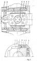
- the wing bearing adjustment plates 4 are inserted through openings in the rear end face of the hub and are inclined to the axis of the propeller shaft 1 and radially fixed by a centering ring 5.
- the axially displaceable holding and adjusting yoke 8 which is supported against rotation on the one-piece propeller hub 2 in a yoke guide 7, engages via adjusting pins and sliding pieces 9 in oblique grooves 10 of the wing bearing adjusting plates 4.
- the holding and setting yoke 8 is connected by means of a thread to an axially immovable rotatable threaded spindle or bush 11 and is thereby held in the respectively set position or brought into the predetermined position by turning the threaded spindle or bush 11.
- a worm wheel 12 is fixedly attached to the threaded spindle or bushing 11 and is in engagement with a worm 14 driven by one-way driving clutches 13.
- a preferably two-part housing 19 for receiving an electromagnet device 20 is fastened to the stern ship 18.
- the longitudinal section in FIG. 1 further shows coil cores 21, coil windings 22 and coil cover 23 of the non-rotatably arranged electromagnetic device 20 in the preferably semi-ring-shaped housing 19.
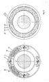
- Fig. 2 the upper figure shows a top view of a one-piece propeller hub 2 of a setting propeller and on a laterally flattened wing bearing setting plate 4 with oblique grooves 10, centering ring 5 and side support plates 6, holding and setting yoke inserted from behind in the one-piece propeller hub 2 8.
- the lower figure shows a cross section through the propeller shaft 1, one-piece propeller hub 2, wing bearing adjustment plate 4, centering ring 5 and side support plates 6.
- Fig. 3 shows a longitudinal section through a multi-part propeller hub 3 of a four-bladed adjusting propeller with inner and outer hub with conical press connection on the propeller shaft 1 and axially parallel wing bearing adjusting plates 4 with adjusting pins and sliding pieces 9 and the holding and adjusting yoke 8 with oblique grooves 10.
- the hold - And setting yoke 8 is supported on the outer hub against rotation and is held in the respectively set position via thread and threaded spindle or bushing 11 or via worm wheel 12, one-way driving clutches 13, worm 14, pulling devices 15, permanent magnet groups 16 and electromagnetic device 20 in brought the given position.
- FIG. 4 shows in the left figure a view of the end of the two-part propeller hub 3 facing the ship, with two permanent magnet groups 16 and pulling device 15 arranged axially displaceably in the hub.
- the two-part electromagnetic device 20 with coil cores 21 arranged on the stern ship 18 is shown and coil windings 22 shown.
Landscapes
- Engineering & Computer Science (AREA)
- Aviation & Aerospace Engineering (AREA)
- Chemical & Material Sciences (AREA)
- Combustion & Propulsion (AREA)
- Mechanical Engineering (AREA)
- Ocean & Marine Engineering (AREA)
- Structures Of Non-Positive Displacement Pumps (AREA)
- Toys (AREA)
- Mixers Of The Rotary Stirring Type (AREA)
Applications Claiming Priority (4)
| Application Number | Priority Date | Filing Date | Title |
|---|---|---|---|
| DD31330588A DD269363B1 (de) | 1988-03-02 | 1988-03-02 | Einrichtung zur steigungsveraenderung der propellerfluegel von einstellpropellern |
| DD313305 | 1988-03-02 | ||
| DD32188188 | 1988-11-17 | ||
| DD321881 | 1988-11-17 |
Publications (1)
| Publication Number | Publication Date |
|---|---|
| EP0336054A1 true EP0336054A1 (fr) | 1989-10-11 |
Family
ID=25748193
Family Applications (1)
| Application Number | Title | Priority Date | Filing Date |
|---|---|---|---|
| EP19890101153 Withdrawn EP0336054A1 (fr) | 1988-03-02 | 1989-01-23 | Hélice à pas variable |
Country Status (7)
| Country | Link |
|---|---|
| EP (1) | EP0336054A1 (fr) |
| JP (1) | JPH026292A (fr) |
| CN (1) | CN1013184B (fr) |
| DK (1) | DK83289A (fr) |
| FI (1) | FI890014A (fr) |
| NO (1) | NO890394L (fr) |
| PL (1) | PL277489A1 (fr) |
Cited By (1)
| Publication number | Priority date | Publication date | Assignee | Title |
|---|---|---|---|---|
| CN114940251A (zh) * | 2022-04-29 | 2022-08-26 | 广东逸动科技有限公司 | 螺旋桨、推进器及水上设备 |
Families Citing this family (9)
| Publication number | Priority date | Publication date | Assignee | Title |
|---|---|---|---|---|
| US4954885A (en) * | 1987-02-25 | 1990-09-04 | Mitsubishi Denki Kabushiki Kaisha | Filter for separating luminance and chrominance signals from composite color television signal |
| AU2003903902A0 (en) * | 2003-07-25 | 2003-08-07 | Aimbridge Pty Ltd | Marine propulsion system |
| CN101318547B (zh) * | 2008-05-23 | 2010-09-08 | 哈尔滨工程大学 | 水下运动体变螺距推进装置 |
| CN107428402B (zh) * | 2015-03-05 | 2019-04-16 | 瓦锡兰荷兰公司 | 布置海洋船舶的可控桨距式推进器装置的润滑的方法及其润滑装置 |
| WO2017187746A1 (fr) * | 2016-04-27 | 2017-11-02 | 川崎重工業株式会社 | Hélice de navire |
| CN106628080B (zh) * | 2017-01-16 | 2019-01-11 | 苏州船用动力系统股份有限公司 | 一种桨叶变距用装置 |
| CN108945364B (zh) * | 2018-05-25 | 2021-01-19 | 南京高精船用设备有限公司 | 一种基于分体式导架结构的大型船舶推进器 |
| CN108557046B (zh) * | 2018-05-30 | 2019-11-15 | 武汉船用机械有限责任公司 | 轴式配油器 |
| CN109927868B (zh) * | 2019-01-31 | 2021-08-10 | 武汉船用机械有限责任公司 | 调距桨的固定结构 |
Citations (5)
| Publication number | Priority date | Publication date | Assignee | Title |
|---|---|---|---|---|
| DD80634A (fr) * | ||||
| NL36986C (fr) * | 1900-01-01 | |||
| CH247914A (de) * | 1943-10-02 | 1947-03-31 | Sulzer Ag | Schiffsschraube mit im Betrieb verstellbaren Flügeln. |
| DE962579C (de) * | 1954-03-30 | 1957-04-25 | Arne Feroy | Verstellpropeller |
| GB2094924A (en) * | 1981-03-13 | 1982-09-22 | Amiot Expl Procedes Felix | Device for allowing hand drive of a normally power driven member |
-
1989
- 1989-01-03 FI FI890014A patent/FI890014A/fi not_active IP Right Cessation
- 1989-01-23 EP EP19890101153 patent/EP0336054A1/fr not_active Withdrawn
- 1989-01-31 NO NO89890394A patent/NO890394L/no unknown
- 1989-02-01 PL PL27748989A patent/PL277489A1/xx unknown
- 1989-02-17 JP JP3813289A patent/JPH026292A/ja active Pending
- 1989-02-23 DK DK83289A patent/DK83289A/da not_active Application Discontinuation
- 1989-02-28 CN CN 89100999 patent/CN1013184B/zh not_active Expired
Patent Citations (5)
| Publication number | Priority date | Publication date | Assignee | Title |
|---|---|---|---|---|
| DD80634A (fr) * | ||||
| NL36986C (fr) * | 1900-01-01 | |||
| CH247914A (de) * | 1943-10-02 | 1947-03-31 | Sulzer Ag | Schiffsschraube mit im Betrieb verstellbaren Flügeln. |
| DE962579C (de) * | 1954-03-30 | 1957-04-25 | Arne Feroy | Verstellpropeller |
| GB2094924A (en) * | 1981-03-13 | 1982-09-22 | Amiot Expl Procedes Felix | Device for allowing hand drive of a normally power driven member |
Cited By (1)
| Publication number | Priority date | Publication date | Assignee | Title |
|---|---|---|---|---|
| CN114940251A (zh) * | 2022-04-29 | 2022-08-26 | 广东逸动科技有限公司 | 螺旋桨、推进器及水上设备 |
Also Published As
| Publication number | Publication date |
|---|---|
| FI890014A0 (fi) | 1989-01-03 |
| DK83289A (da) | 1989-09-03 |
| FI890014A (fi) | 1989-09-03 |
| PL277489A1 (en) | 1989-10-30 |
| NO890394L (no) | 1989-09-04 |
| DK83289D0 (da) | 1989-02-23 |
| NO890394D0 (no) | 1989-01-31 |
| CN1036535A (zh) | 1989-10-25 |
| CN1013184B (zh) | 1991-07-17 |
| JPH026292A (ja) | 1990-01-10 |
Similar Documents
| Publication | Publication Date | Title |
|---|---|---|
| DE1613346C3 (de) | Kupplungsmotor | |
| DE102010039394A1 (de) | Verstellpropeller oder -repeller | |
| EP0336054A1 (fr) | Hélice à pas variable | |
| DE3443523A1 (de) | Zweistufenkupplung, insbesondere fuer den antrieb eines kuehlluefters | |
| EP2262989B1 (fr) | Embrayage à friction et système d entraînement pour le refroidissement d un moteur à combustion d un véhicule équipé d un embrayage à friction | |
| DE3406634A1 (de) | Vorrichtung zum verstellen des anstellwinkels einer luftschraube | |
| EP0460666B1 (fr) | Rétroviseur extérieur de véhicule à fonctionnement électrique | |
| DE2732987A1 (de) | Bohrgeraet mit steuerung des drehantriebs | |
| DE4022735A1 (de) | Spielfreie phaseneinstellvorrichtung | |
| DE4201161C2 (de) | Vorrichtung zum Ausfahren und Einziehen einer Teleskopantenne für ein Fahrzeug | |
| DE1811845A1 (de) | Servolenkung | |
| EP0641499B1 (fr) | Moteur electrique rotatif d'entrainement d'un vehicule | |
| DE1488672C3 (de) | Elektrischer Kupplungsmotor mit Bremse | |
| DE102006007915B4 (de) | Antriebssystem mit einem Verstellpropeller | |
| DE2834579C2 (de) | Motor | |
| DE681221C (de) | Vorrichtung zur schrittweisen Fernbedienung eines in Stufen zu verstellenden Geraets | |
| DE1951080A1 (de) | Elektromotorische Verstellvorrichtung | |
| DE2362825C2 (de) | Ziehvorrichtung für Kristalle | |
| DE2626695A1 (de) | Einrichtung zum verstellen der drehzahl einer antriebsvorrichtung | |
| DE19943019A1 (de) | Hydrodynamische Vorrichtung | |
| DD269363B1 (de) | Einrichtung zur steigungsveraenderung der propellerfluegel von einstellpropellern | |
| EP1484658A1 (fr) | Actionneur pour contrôle de debit d'un fluide et membre guide pour un fluide avec un actionneur | |
| EP0978401A1 (fr) | Dispositif d' actionnement pour déplacer des éléments mobiles pour véhicules au moyen d'un moteur de positionnement court-circuitable | |
| DE444943C (de) | Verstellpropeller, insbesondere fuer Luftfahrzeuge | |
| DE102022114224A1 (de) | Axialflussmaschine mit Feldschwächung durch Stromstellung |
Legal Events
| Date | Code | Title | Description |
|---|---|---|---|
| PUAI | Public reference made under article 153(3) epc to a published international application that has entered the european phase |
Free format text: ORIGINAL CODE: 0009012 |
|
| AK | Designated contracting states |
Kind code of ref document: A1 Designated state(s): CH DE ES FR GB GR LI NL SE |
|
| 17P | Request for examination filed |
Effective date: 19900328 |
|
| RAP1 | Party data changed (applicant data changed or rights of an application transferred) |
Owner name: INGENIEURZENTRUM SCHIFFBAU GMBH |
|
| 17Q | First examination report despatched |
Effective date: 19910531 |
|
| STAA | Information on the status of an ep patent application or granted ep patent |
Free format text: STATUS: THE APPLICATION IS DEEMED TO BE WITHDRAWN |
|
| 18D | Application deemed to be withdrawn |
Effective date: 19911011 |