EP0335859A2 - Dispositif de mesure de composants présents dans un échantillon - Google Patents
Dispositif de mesure de composants présents dans un échantillon Download PDFInfo
- Publication number
- EP0335859A2 EP0335859A2 EP89890082A EP89890082A EP0335859A2 EP 0335859 A2 EP0335859 A2 EP 0335859A2 EP 89890082 A EP89890082 A EP 89890082A EP 89890082 A EP89890082 A EP 89890082A EP 0335859 A2 EP0335859 A2 EP 0335859A2
- Authority
- EP
- European Patent Office
- Prior art keywords
- sample
- channel
- sensor
- sensor module
- reagent
- Prior art date
- Legal status (The legal status is an assumption and is not a legal conclusion. Google has not performed a legal analysis and makes no representation as to the accuracy of the status listed.)
- Granted
Links
Images

Classifications
-
- G—PHYSICS
- G01—MEASURING; TESTING
- G01N—INVESTIGATING OR ANALYSING MATERIALS BY DETERMINING THEIR CHEMICAL OR PHYSICAL PROPERTIES
- G01N35/00—Automatic analysis not limited to methods or materials provided for in any single one of groups G01N1/00 - G01N33/00; Handling materials therefor
Definitions
- the invention relates to a device for measuring sample components present in a sample, with a sensor block with at least one sensor module, in the housing of which a measuring chamber which is in contact with the sensor is arranged.
- a device of the type mentioned at the outset is known, for example, from AT-PS 381 794, which in the exemplary embodiment shown has three sensor modules combined to form a sensor block, through which a sample channel designed as a central capillary bore passes.
- ion-sensitive capillary electrodes known from AT-PS 363 263 can be used as sensor modules, which are clamped against a fixed abutment of the sensor block by means of a pressing mechanism.
- the sensor modules known from the cited documents are only suitable for the direct measurement of a sample component of interest, an indirect measurement is not possible with the known device.
- indirect measurement is to be understood to mean that the sample is modified in a specific volume ratio by mixing with a reagent before the measurement of a sample component of interest, the desired size being generated indirectly, for example via a proportion of the sample component of interest that is present in proportion to the amount present Reaction product to which the sensor used responds is measured.
- direct measurement means that the sensor used is able to directly through the sample component of interest without modification or change of the sample material convert a specific measuring element into an evaluable signal.
- EP-A 0 163 976 a measuring device similar to that from AT-PS 381 794 is known, the most noticeable difference being that the sample and the calibration reagents are sucked in from the opposite side of the sensor module, whereby the end the reference electrode arranged on the sensor module disadvantageously contaminates the measuring medium when suction is carried out from this side.
- a sensor module for indirect measurement is also not available in this measuring device.
- the object of the present invention is to propose a measuring device with which reproducible indirect measurements of sample components present in a sample can be carried out without great expenditure on equipment, with small sample and reagent volumes being sufficient to obtain a measured value.
- a mixing chamber connected upstream of the measuring chamber and connected to a sample channel and a reagent channel is arranged in the housing of the sensor module. Due to the modular structure of the sensor block, the sample and reagent paths in the sensor block or in the sensor module can be kept short, so that together with the compact arrangement of the mixing and measuring chamber, only minimal sample and reagent tel quantities are required. Depending on the type of sample components to be measured, sensors with different measuring principles can be used in the sensor module. By mixing the sample with one or more reagents supplied simultaneously via the reagent channel, a reaction product that can be detected by the sensor is present after their reaction.
- a magnetic stirrer which can be set in motion by means of magnetic conductors which are connected to a magnetic coil.
- the housing of the sensor module has an interchangeable mixer part, in which the mixing chamber with the magnetic stirrer is arranged, the mixer part having connections for the sample channel, the reagent channel and the channel to the measuring chamber, and two arranged in the mixer part the mixing chamber directed magnetic conductors are present. Because the magnetic force for driving the magnetic stirrer is brought to the mixing chamber via magnetic conductors, the mixer part containing the mixing chamber can be produced in a very compact manner. Removing the mixer part, for example in order to clean it or to replace worn parts or to replace the entire mixer part with a new one, is easily possible after removing the sensor module from the sensor block.
- the invention provides that the sensor module can be clamped in a manner known per se by means of a pressing mechanism against a fixed abutment of the sensor block, the sample channel of the sensor module being tightly connectable to a channel section in the abutment, and that the magnet coil is arranged in a pressure body part of the pressure mechanism, which can be pressed onto the mixer part by means of spring elements, and that magnetic conductors leading away from the magnet coil are present in the pressure body part and bear against the magnet conductors in the mixer part.
- the replacement of the mixer part is thereby inventively relieved that the housing of the sensor module on its side facing a base plate has a resilient holding button which presses the interchangeable mixer part after its insertion into the housing in the direction of the measuring chamber.
- the mixer part of the sensor module has a closure part which closes the mixing chamber and whose central bore is sealed off from the channel to the measuring chamber, the closure part having a cylindrical extension projecting into the mixing chamber.
- This closure part brings advantages in terms of manufacturing technology, in particular for the mixer part, sealing and protective functions for the mixing chamber being fulfilled in the installed state at the same time.
- the senor it is of course also possible for the sensor to protrude into a part of the mixing chamber which is designed as a measuring chamber. This will be the case in particular if reagents are used which do not have any deleterious influence on the sensor or the sensor membrane. It is only necessary to ensure that mechanical damage to the sensor is prevented by a magnetic stirrer that may be present.
- At least one sensor module known per se for direct measurement of sample components can be inserted, the connection of which seals the sample channel of the adjacent sensor module and the other connection sealingly connects to the channel section in the abutment.
- sensors can be used for the direct measurement of sample components, which are described in detail in AT-PSs 363 263, 379 318 and 380 741.
- the ion-sensitive mem branch electrode for measuring the ion concentration of a sample according to AT-PS 379 318, and the aforementioned ion-sensitive capillary electrode according to AT-PS 363 263 on a sample channel axially penetrating the sensor module so that these sensors are particularly suitable, lined up in a sensor block, in Connection with the sensor module according to the invention to be used for indirect measurement.
- a measuring device for joint indirect and direct measurement of sample components of a sample can be realized in the following, which will be described in more detail below.
- the channel section in the abutment is made of an electrically conductive material and is connected to an electrically conductive cable.
- the sample can thus be brought to a certain potential, for example to earth potential.
- suitable optical sensors or optodes in the individual sensor modules, in which case, of course, no grounding or reference electrodes are necessary.
- the sensor module has a CO2 sensor for measuring the total CO2 content of a blood serum sample.
- the entire CO2 consists in a blood serum sample from dissolved CO2 and the bicarbonate content of the sample.
- the CO2 chemically bound in the bicarbonate is driven out by an acidic reagent that is added. This creates a high partial pressure of the molecularly dissolved CO2, which is measured with the CO2 sensor.
- This principle can of course be applied to many other reactions, for example to measure the total content of Ca ions. It can be particularly advantageous if the substance to be measured is in gaseous form if the measuring chamber is arranged vertically above the mixing chamber.
- a measuring device with an input device connected to the sample channel of the sensor module for sample and standard media, containers for the standard media, and a feed pump for transporting the individual media
- the measuring device known from AT-PS 381 794 the improvements mentioned above lead to a measuring device for joint direct and indirect measurement of sample components present in a sample.
- the arrangement of the hose pump common for the sample and reagent in front of the sensor block ensures a constant mixing ratio between the two substances, the mixture ratio between sample and reagent required for the reaction sequence according to the invention being determined by the ratio of the cross sections of the hose lines leading to the reagent channel and the sample channel can be defined.
- the reagent can advantageously also be used as a reference medium if, when using at least one electrochemical sensor, a reference electrode is arranged in one of the sensor modules in the reagent channel, preferably outside the sensor block.
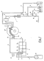
- FIG. 1 shows a device according to the invention in a schematic illustration
- FIG. 2 shows a sensor block of the device according to the invention partially in section
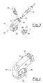
- FIGS. 3 and 4 show a sensor module from the sensor block according to FIG. 2 in detail.
- the sample input device 1 is connected to a sensor block 3 via a hose line 2 into which a light barrier S for checking the sample or standard medium passage is connected.
- the sensor block 3 is shown in the Example th three sensor modules E1, E2 and E3 for direct and a sensor module M for indirect measurement of sample components, which are connected via a sample channel 4 designed as a central capillary bore and are acted upon by the flowing sample.
- the sensors here have signal lines (not shown further), each of which emits measurement signals proportional to the quantity to be measured for evaluation.
- the reagent required for the reaction in the mixing chamber 5 of the sensor module M for the indirect measurement of sample components is fed to the reagent channel 7 of the sensor module M via a hose 6, which can be opened or closed by means of a control valve 22 .
- the mixture enters the measuring chamber 8 and from there via a line 9 into a waste container 10.
- both the hose line 6 performed for the reagent and the hose line 2 for the sample, the mixing ratio for the sample-reagent mixture being determined by the ratio of the cross sections D 1, D 2 of the hose lines 2 and 6.
- two further containers 12, 13 are provided in the measuring device, which contain certain different standard solutions or the like and are connected to a feed line 18 to the sample input device 1 via hose lines 14, 15 and control valves 16, 17 .
- the feed line 18 also has an opening 20, which can be closed by means of a further control valve 19, for sucking in air.
- the supplied appropriate reference electrode 21 outside the sensor block 3 directly into the reagent channel 7 or, as shown in FIG. 1, into the hose line 6 carrying the reagent.
- the reagent is thus also used as a reference solution.
- a combination of an indirectly measuring sensor module M and of directly measuring sensor modules E1, E2, E3 is shown in the sensor block 3 shown in FIG. 2 in detail.
- the known sensor modules E 1 to E 3 and a sensor module M to be described in more detail for indirect measurement of a sample component are arranged.
- the abutment 23 and the pressure mechanism 24 are firmly screwed to a base plate 30.
- a modified form would also be conceivable for sensor arrangements in which the sensor module M is clamped directly against the abutment 23.
- the abutment 23 has a channel section 31, with which the sample channel 4 of the sensor module in contact with the abutment is connected with the interposition of a sealing element 32.
- the channel section 31 is designed to be electrically conductive and is connected to an electrical connecting cable 46.
- the channel section 31 can be connected to a defined electrical potential via this connecting cable. Since the sample flows through the channel section 31, it can thus be brought to a specific electrical potential. This will usually be used to ground the sample.
- the sensor module M has a housing 25 with an opening 26 for inserting an electrochemical sensor 27 shown in FIG. 3.
- the sensor 27 used delimits the measuring chamber 8 with its sensor membrane, from which a channel 28 leads to the mixing chamber 5 arranged in an exchangeable mixer part 29.
- a magnetic stirrer 33 which is set in motion by means of non-permanently magnetic magnetic conductors 34 arranged in the mixer part 29.
- the magnetic coil 35 for supplying the magnetic conductor 34 is arranged in a pressure body part 36.
- This pressure body part 36 is located in a recess of the pressure body 37 of the pressure mechanism 24 and is pressed by means of a spring element 38 supported on the pressure body 37 against the exchangeable mixer part 29, magnetic conductors 39 leading away from the magnet coil 35 and arranged in the pressure body part 36 being in contact with those in the mixer part 29 come (only one ferromagnetic, not permanently magnetic magnetic conductor 34, 39 is visible in the sectional plane shown)
- the mixer part 29 has a closure part 40 which closes the mixer chamber 5 in the direction of the measuring chamber 8, the central bore 41 of which is sealed by a seal 42 against the channel 28 to the measuring chamber 8.
- a cylindrical jacket-shaped extension 43 of the closure part 40 protruding into the mixing chamber 5 protects the walls of the mixing chamber from the wear caused by the magnetic stirrer.
- the magnetic stirrer 33 begins to wobble.
- the reagent channel 7 leads into the mixer part and opens into the sample channel 4 just before the mixing chamber. Through the channel 7, a reagent is mixed into the sample, which reacts in the mixing chamber the sample is thoroughly mixed. This mixing and the subsequent reaction results in a reaction product which is in a known quantitative relationship to the sample component which is to be measured, this reaction product by the sensor 27 projecting into the measuring chamber 5 can be measured.
- the sample-reagent mixture is discharged through line 9 into waste container 10 (FIG. 1).
- the pressing mechanism 24 allows the sensor modules E 1, E 2, E 3 and M to be pressed together axially, so that the sealing elements 32 come into sealing engagement along the sample channel 4.
- the axial displacement of the pressure body 37 is accomplished with the aid of a threaded screw 47 fastened to the base plate 30 and a movable threaded screw 48, the latter 48 being able to be rotated with the lever 49 and acting on the pressure body 37 via compression springs 50.
- the pressure body 37 In the drawn position of the lever 49, the pressure body 37 is biased against the force of the springs 50 in the axial direction in such a way that it presses the sensor modules together via the extension 51 or presses the mixer part 29 onto the adjacent sensor module E 1.
- a part of the pressure body 37 is designed as a cover 52 of the pressing mechanism.
- Fig. 3 shows the individual parts of the sensor module M removed from the sensor block, which consists of a housing 25 into which on the one hand a mixer part 29 and on the other hand the sensor 27 used for the measurement can be inserted, which inside against the measuring chamber through the sealing ring 53 is sealed and is locked with a retaining clip 55 which engages in a groove 54 in the housing 25.
- the sample channel 4, the reagent channel 7 and the channel 28 arranged in the closure part 40 are visible on the mixer part 29.
- the mixer part 29 can be pushed into the housing of the sensor module M from the view side and is locked in place by the resilient holding button 45.
Landscapes
- General Health & Medical Sciences (AREA)
- Health & Medical Sciences (AREA)
- Life Sciences & Earth Sciences (AREA)
- Chemical & Material Sciences (AREA)
- Analytical Chemistry (AREA)
- Biochemistry (AREA)
- Physics & Mathematics (AREA)
- General Physics & Mathematics (AREA)
- Immunology (AREA)
- Pathology (AREA)
- Investigating Or Analysing Biological Materials (AREA)
- Automatic Analysis And Handling Materials Therefor (AREA)
- Investigating Or Analyzing Non-Biological Materials By The Use Of Chemical Means (AREA)
Applications Claiming Priority (2)
| Application Number | Priority Date | Filing Date | Title |
|---|---|---|---|
| AT0083088A AT391950B (de) | 1988-03-28 | 1988-03-28 | Vorrichtung zur messung von in einer probe vorliegenden probenbestandteilen |
| AT830/88 | 1988-03-28 |
Publications (3)
| Publication Number | Publication Date |
|---|---|
| EP0335859A2 true EP0335859A2 (fr) | 1989-10-04 |
| EP0335859A3 EP0335859A3 (en) | 1990-08-29 |
| EP0335859B1 EP0335859B1 (fr) | 1993-07-21 |
Family
ID=3500758
Family Applications (1)
| Application Number | Title | Priority Date | Filing Date |
|---|---|---|---|
| EP89890082A Expired - Lifetime EP0335859B1 (fr) | 1988-03-28 | 1989-03-20 | Dispositif de mesure de composants présents dans un échantillon |
Country Status (5)
| Country | Link |
|---|---|
| US (1) | US5017339A (fr) |
| EP (1) | EP0335859B1 (fr) |
| JP (1) | JPH01285861A (fr) |
| AT (1) | AT391950B (fr) |
| DE (1) | DE58904936D1 (fr) |
Cited By (1)
| Publication number | Priority date | Publication date | Assignee | Title |
|---|---|---|---|---|
| WO1998030892A1 (fr) * | 1997-01-14 | 1998-07-16 | Eidgenössische Technische Hochschule Zürich | Systeme modulaire de capteurs utile pour la technique de mesure de processus industriels |
Families Citing this family (10)
| Publication number | Priority date | Publication date | Assignee | Title |
|---|---|---|---|---|
| US6270890B1 (en) | 1988-03-29 | 2001-08-07 | Colgate-Palmolive Company | Dental floss |
| AT391030B (de) * | 1988-12-01 | 1990-08-10 | Avl Verbrennungskraft Messtech | Vorrichtung zur messung chemischer und physikalischer parameter eines fluessigen oder gasfoermigen mediums |
| JP2502897Y2 (ja) * | 1990-10-19 | 1996-06-26 | オリンパス光学工業株式会社 | イオン濃度自動分析装置 |
| US5525197A (en) * | 1992-10-26 | 1996-06-11 | Coulson; Dale M. | Electrochemical detector cell, method and pyrolysis furnace |
| EP0793094A3 (fr) * | 1996-03-01 | 1998-02-11 | Orion Research Incorporated | Ensemble support à friction pour électrode et agitateur |
| US6066243A (en) | 1997-07-22 | 2000-05-23 | Diametrics Medical, Inc. | Portable immediate response medical analyzer having multiple testing modules |
| EP0953842A1 (fr) * | 1998-05-01 | 1999-11-03 | F. Hoffmann-La Roche Ag | Analysateur automatique avec chambre de mélange amincie au dessous et unité de base liée étanchement à la chambre de mélange |
| NL1013072C2 (nl) * | 1999-09-17 | 2001-03-20 | Stichting Fund Ond Material | Analyse-inrichting voor het detecteren van in water opgeloste bestanddelen. |
| DE102020109889A1 (de) * | 2020-04-08 | 2021-10-14 | Testo SE & Co. KGaA | Messvorrichtung mit einem Gehäuse und eine korrespondierende Verwendung |
| JP7611788B2 (ja) * | 2021-08-06 | 2025-01-10 | 株式会社日立ハイテク | 電解質測定用構造およびそれを用いたフロー型イオン選択性電極、ならびに電解質測定装置 |
Family Cites Families (10)
| Publication number | Priority date | Publication date | Assignee | Title |
|---|---|---|---|---|
| US4097921A (en) * | 1975-07-22 | 1978-06-27 | Luigi Rossi | Method and apparatus for automatically determining the dilution curve of a solution, particularly the oxygen dissociation curve of blood or hemoglobin solutions |
| DE2726772A1 (de) * | 1977-06-14 | 1979-01-04 | Fresenius Chem Pharm Ind | Mehrfachmessystem fuer die elektrochemische analyse stroemender fluessigkeiten und gase |
| US4353867A (en) * | 1980-09-30 | 1982-10-12 | Massimo Luzzana | Method and apparatus for the determination of substances in biological solutions by differential pH measurement |
| US4409088A (en) * | 1981-06-30 | 1983-10-11 | Tokyo Shibaura Denki Kabushiki Kaisha | Regeneration method of ion-selective electrode, and ion-selective electrode and ion-concentration analyzer containing means adapted to practice said method |
| JPS5887464A (ja) * | 1981-11-20 | 1983-05-25 | Hitachi Ltd | 連続流れ方式自動分析方法 |
| FR2545905B1 (fr) * | 1983-05-13 | 1987-11-27 | Ferracci Francois | Dispositif de mesure de caracteristiques d'un liquide, et robinet destine notamment a un tel dispositif |
| US4535786A (en) * | 1983-07-25 | 1985-08-20 | Kater John A R | Measurement of body fluid chemistry |
| AT381794B (de) * | 1984-02-02 | 1986-11-25 | Avl Verbrennungskraft Messtech | Analysengeraet zur messung fluessiger oder gasfoermiger proben |
| DE3416956C2 (de) * | 1984-05-08 | 1986-12-04 | Fresenius AG, 6380 Bad Homburg | Meßvorrichtung zur Bestimmung der Aktivität oder der Konzentration von Ionen in Lösungen |
| CH663282A5 (de) * | 1984-07-13 | 1987-11-30 | Zellweger Uster Ag | Vorrichtung zur messung geringer ionenaktivitaetswerte eines probenstroms. |
-
1988
- 1988-03-28 AT AT0083088A patent/AT391950B/de not_active IP Right Cessation
-
1989
- 1989-03-20 DE DE8989890082T patent/DE58904936D1/de not_active Expired - Fee Related
- 1989-03-20 EP EP89890082A patent/EP0335859B1/fr not_active Expired - Lifetime
- 1989-03-28 JP JP1077928A patent/JPH01285861A/ja active Pending
- 1989-03-28 US US07/329,837 patent/US5017339A/en not_active Expired - Fee Related
Cited By (2)
| Publication number | Priority date | Publication date | Assignee | Title |
|---|---|---|---|---|
| WO1998030892A1 (fr) * | 1997-01-14 | 1998-07-16 | Eidgenössische Technische Hochschule Zürich | Systeme modulaire de capteurs utile pour la technique de mesure de processus industriels |
| US6409909B1 (en) | 1997-01-14 | 2002-06-25 | Eidgenossische Technische Hochschule Zurich | Modular sensor system for the industrial process measurement technique |
Also Published As
| Publication number | Publication date |
|---|---|
| EP0335859A3 (en) | 1990-08-29 |
| JPH01285861A (ja) | 1989-11-16 |
| EP0335859B1 (fr) | 1993-07-21 |
| AT391950B (de) | 1990-12-27 |
| ATA83088A (de) | 1990-06-15 |
| US5017339A (en) | 1991-05-21 |
| DE58904936D1 (de) | 1993-08-26 |
Similar Documents
| Publication | Publication Date | Title |
|---|---|---|
| DE2554803C2 (de) | Elektrochemisches Analyseverfahren sowie Vorrichtung zur Durchführung des Verfahrens | |
| EP2002255B1 (fr) | Procédé d'analyse de proportions d'isotopes | |
| EP2340432B1 (fr) | Procédé d'analyse d'un analyte dans un échantillon d'eau à l'aide d'un dispositif d'analyse d'eau mobile | |
| AT399228B (de) | Verfahren zur analyse von gasförmigen oder flüssigen proben und einweg-messelement zur ausübung des verfahrens | |
| DE1673032A1 (de) | Verfahren und Vorrichtung zum Messen der Gas- oder Dampfdurchlaessigkeit von Filmen | |
| AT391950B (de) | Vorrichtung zur messung von in einer probe vorliegenden probenbestandteilen | |
| DE2528819A1 (de) | Analysegeraet | |
| EP0722567A1 (fr) | Dispositif de mesure destine a l'analyse de fluides | |
| AT401689B (de) | Verfahren und vorrichtung zum vermischen zweier ausgangslösungen | |
| EP2581344A1 (fr) | Agencement de traitement de liquides, notamment de traitement de l'eau | |
| WO2002074043A2 (fr) | Dispositif d'analyse de fluides | |
| DE19731889A1 (de) | Verfahren zur Kalibrierung von Isotopenanalysatoren | |
| DE2900720C2 (fr) | ||
| DE102010016103B4 (de) | Messvorrichtung mit Resonator | |
| EP0624395A1 (fr) | Chambre de mélange | |
| DE19544851A1 (de) | Vorrichtung zur Untersuchung von Flüssigkeitsproben | |
| EP0727655A1 (fr) | Dispositif et procédé de mesure de la perméabilité d'oxygène d'un échantillon | |
| DE19532382A1 (de) | Vorrichtung zur Analyse chemischer oder physikalischer Veränderungen in einer Probeflüssigkeit | |
| DE10132390B4 (de) | Vorrichtung und Verfahren zur Analyse organischer Substanzen von Rein- oder Reinstwasser | |
| DE3004347A1 (de) | Probenaufgabevorrichtung fuer gaschromatographen | |
| DE102004020287A1 (de) | Vorrichtung zur Bestimmung des Energieinhaltes von einem Gas | |
| DE2125900A1 (de) | Verfahren und Gerät zum Reduzieren der Konzentration eines Bestandteiles eines Gases oder einer Flüssigkeit | |
| DE10057895A1 (de) | Vorrichtung und Verfahren zur Probenvorbereitung flüssiger Proben | |
| CH520933A (de) | Verfahren zur chemischen Analyse von in gelöstem Zustand vorhandenen Stoffen und Einrichtung zur Durchführung des Verfahrens | |
| DE3618520A1 (de) | Verfahren und vorrichtung zur bestimmung des endpunkts von titrationen |
Legal Events
| Date | Code | Title | Description |
|---|---|---|---|
| PUAI | Public reference made under article 153(3) epc to a published international application that has entered the european phase |
Free format text: ORIGINAL CODE: 0009012 |
|
| AK | Designated contracting states |
Kind code of ref document: A2 Designated state(s): DE FR GB |
|
| GBC | Gb: translation of claims filed (gb section 78(7)/1977) | ||
| EL | Fr: translation of claims filed | ||
| RAP1 | Party data changed (applicant data changed or rights of an application transferred) |
Owner name: AVL MEDICAL INSTRUMENTS AG |
|
| PUAL | Search report despatched |
Free format text: ORIGINAL CODE: 0009013 |
|
| AK | Designated contracting states |
Kind code of ref document: A3 Designated state(s): DE FR GB |
|
| 17P | Request for examination filed |
Effective date: 19901219 |
|
| 17Q | First examination report despatched |
Effective date: 19921215 |
|
| GRAA | (expected) grant |
Free format text: ORIGINAL CODE: 0009210 |
|
| AK | Designated contracting states |
Kind code of ref document: B1 Designated state(s): DE FR GB |
|
| GBT | Gb: translation of ep patent filed (gb section 77(6)(a)/1977) |
Effective date: 19930726 |
|
| REF | Corresponds to: |
Ref document number: 58904936 Country of ref document: DE Date of ref document: 19930826 |
|
| ET | Fr: translation filed | ||
| PG25 | Lapsed in a contracting state [announced via postgrant information from national office to epo] |
Ref country code: GB Effective date: 19940320 |
|
| PLBE | No opposition filed within time limit |
Free format text: ORIGINAL CODE: 0009261 |
|
| STAA | Information on the status of an ep patent application or granted ep patent |
Free format text: STATUS: NO OPPOSITION FILED WITHIN TIME LIMIT |
|
| 26N | No opposition filed | ||
| GBPC | Gb: european patent ceased through non-payment of renewal fee |
Effective date: 19940320 |
|
| PG25 | Lapsed in a contracting state [announced via postgrant information from national office to epo] |
Ref country code: FR Effective date: 19941130 |
|
| PG25 | Lapsed in a contracting state [announced via postgrant information from national office to epo] |
Ref country code: DE Effective date: 19941201 |
|
| REG | Reference to a national code |
Ref country code: FR Ref legal event code: ST |