EP0334708B1 - Anordnung zur Befestigung von zwei Stücken durch Anpressen und Gehäuse für ein integriertes Schaltungsbauelement mit dieser Anordnung - Google Patents
Anordnung zur Befestigung von zwei Stücken durch Anpressen und Gehäuse für ein integriertes Schaltungsbauelement mit dieser Anordnung Download PDFInfo
- Publication number
- EP0334708B1 EP0334708B1 EP89400664A EP89400664A EP0334708B1 EP 0334708 B1 EP0334708 B1 EP 0334708B1 EP 89400664 A EP89400664 A EP 89400664A EP 89400664 A EP89400664 A EP 89400664A EP 0334708 B1 EP0334708 B1 EP 0334708B1
- Authority
- EP
- European Patent Office
- Prior art keywords
- column
- integrated circuit
- pressure
- shape memory
- parts
- Prior art date
- Legal status (The legal status is an assumption and is not a legal conclusion. Google has not performed a legal analysis and makes no representation as to the accuracy of the status listed.)
- Expired - Lifetime
Links
Images
Classifications
-
- H—ELECTRICITY
- H10—SEMICONDUCTOR DEVICES; ELECTRIC SOLID-STATE DEVICES NOT OTHERWISE PROVIDED FOR
- H10W—GENERIC PACKAGES, INTERCONNECTIONS, CONNECTORS OR OTHER CONSTRUCTIONAL DETAILS OF DEVICES COVERED BY CLASS H10
- H10W40/00—Arrangements for thermal protection or thermal control
- H10W40/60—Securing means for detachable heating or cooling arrangements, e.g. clamps
- H10W40/611—Bolts or screws
-
- F—MECHANICAL ENGINEERING; LIGHTING; HEATING; WEAPONS; BLASTING
- F16—ENGINEERING ELEMENTS AND UNITS; GENERAL MEASURES FOR PRODUCING AND MAINTAINING EFFECTIVE FUNCTIONING OF MACHINES OR INSTALLATIONS; THERMAL INSULATION IN GENERAL
- F16B—DEVICES FOR FASTENING OR SECURING CONSTRUCTIONAL ELEMENTS OR MACHINE PARTS TOGETHER, e.g. NAILS, BOLTS, CIRCLIPS, CLAMPS, CLIPS OR WEDGES; JOINTS OR JOINTING
- F16B21/00—Means for preventing relative axial movement of a pin, spigot, shaft or the like and a member surrounding it; Stud-and-socket releasable fastenings
- F16B21/10—Means for preventing relative axial movement of a pin, spigot, shaft or the like and a member surrounding it; Stud-and-socket releasable fastenings by separate parts
- F16B21/12—Means for preventing relative axial movement of a pin, spigot, shaft or the like and a member surrounding it; Stud-and-socket releasable fastenings by separate parts with locking-pins or split-pins thrust into holes
-
- F—MECHANICAL ENGINEERING; LIGHTING; HEATING; WEAPONS; BLASTING
- F16—ENGINEERING ELEMENTS AND UNITS; GENERAL MEASURES FOR PRODUCING AND MAINTAINING EFFECTIVE FUNCTIONING OF MACHINES OR INSTALLATIONS; THERMAL INSULATION IN GENERAL
- F16B—DEVICES FOR FASTENING OR SECURING CONSTRUCTIONAL ELEMENTS OR MACHINE PARTS TOGETHER, e.g. NAILS, BOLTS, CIRCLIPS, CLAMPS, CLIPS OR WEDGES; JOINTS OR JOINTING
- F16B2200/00—Constructional details of connections not covered for in other groups of this subclass
- F16B2200/77—Use of a shape-memory material
-
- F—MECHANICAL ENGINEERING; LIGHTING; HEATING; WEAPONS; BLASTING
- F28—HEAT EXCHANGE IN GENERAL
- F28F—DETAILS OF HEAT-EXCHANGE AND HEAT-TRANSFER APPARATUS, OF GENERAL APPLICATION
- F28F2255/00—Heat exchanger elements made of materials having special features or resulting from particular manufacturing processes
- F28F2255/04—Heat exchanger elements made of materials having special features or resulting from particular manufacturing processes comprising shape memory alloys or bimetallic elements
-
- F—MECHANICAL ENGINEERING; LIGHTING; HEATING; WEAPONS; BLASTING
- F28—HEAT EXCHANGE IN GENERAL
- F28F—DETAILS OF HEAT-EXCHANGE AND HEAT-TRANSFER APPARATUS, OF GENERAL APPLICATION
- F28F3/00—Plate-like or laminated elements; Assemblies of plate-like or laminated elements
- F28F3/02—Elements or assemblies thereof with means for increasing heat-transfer area, e.g. with fins, with recesses, with corrugations
- F28F3/06—Elements or assemblies thereof with means for increasing heat-transfer area, e.g. with fins, with recesses, with corrugations the means being attachable to the element
-
- H—ELECTRICITY
- H10—SEMICONDUCTOR DEVICES; ELECTRIC SOLID-STATE DEVICES NOT OTHERWISE PROVIDED FOR
- H10W—GENERIC PACKAGES, INTERCONNECTIONS, CONNECTORS OR OTHER CONSTRUCTIONAL DETAILS OF DEVICES COVERED BY CLASS H10
- H10W40/00—Arrangements for thermal protection or thermal control
- H10W40/20—Arrangements for cooling
- H10W40/231—Arrangements for cooling characterised by their places of attachment or cooling paths
- H10W40/235—Arrangements for cooling characterised by their places of attachment or cooling paths attached to package parts
-
- H—ELECTRICITY
- H10—SEMICONDUCTOR DEVICES; ELECTRIC SOLID-STATE DEVICES NOT OTHERWISE PROVIDED FOR
- H10W—GENERIC PACKAGES, INTERCONNECTIONS, CONNECTORS OR OTHER CONSTRUCTIONAL DETAILS OF DEVICES COVERED BY CLASS H10
- H10W40/00—Arrangements for thermal protection or thermal control
- H10W40/60—Securing means for detachable heating or cooling arrangements, e.g. clamps
- H10W40/625—Clamping parts not primarily conducting heat
-
- H—ELECTRICITY
- H10—SEMICONDUCTOR DEVICES; ELECTRIC SOLID-STATE DEVICES NOT OTHERWISE PROVIDED FOR
- H10W—GENERIC PACKAGES, INTERCONNECTIONS, CONNECTORS OR OTHER CONSTRUCTIONAL DETAILS OF DEVICES COVERED BY CLASS H10
- H10W72/00—Interconnections or connectors in packages
- H10W72/50—Bond wires
- H10W72/531—Shapes of wire connectors
- H10W72/5363—Shapes of wire connectors the connected ends being wedge-shaped
-
- H—ELECTRICITY
- H10—SEMICONDUCTOR DEVICES; ELECTRIC SOLID-STATE DEVICES NOT OTHERWISE PROVIDED FOR
- H10W—GENERIC PACKAGES, INTERCONNECTIONS, CONNECTORS OR OTHER CONSTRUCTIONAL DETAILS OF DEVICES COVERED BY CLASS H10
- H10W72/00—Interconnections or connectors in packages
- H10W72/50—Bond wires
- H10W72/531—Shapes of wire connectors
- H10W72/5366—Shapes of wire connectors the bond wires having kinks
-
- H—ELECTRICITY
- H10—SEMICONDUCTOR DEVICES; ELECTRIC SOLID-STATE DEVICES NOT OTHERWISE PROVIDED FOR
- H10W—GENERIC PACKAGES, INTERCONNECTIONS, CONNECTORS OR OTHER CONSTRUCTIONAL DETAILS OF DEVICES COVERED BY CLASS H10
- H10W72/00—Interconnections or connectors in packages
- H10W72/851—Dispositions of multiple connectors or interconnections
- H10W72/874—On different surfaces
- H10W72/884—Die-attach connectors and bond wires
-
- Y—GENERAL TAGGING OF NEW TECHNOLOGICAL DEVELOPMENTS; GENERAL TAGGING OF CROSS-SECTIONAL TECHNOLOGIES SPANNING OVER SEVERAL SECTIONS OF THE IPC; TECHNICAL SUBJECTS COVERED BY FORMER USPC CROSS-REFERENCE ART COLLECTIONS [XRACs] AND DIGESTS
- Y10—TECHNICAL SUBJECTS COVERED BY FORMER USPC
- Y10S—TECHNICAL SUBJECTS COVERED BY FORMER USPC CROSS-REFERENCE ART COLLECTIONS [XRACs] AND DIGESTS
- Y10S411/00—Expanded, threaded, driven, headed, tool-deformed, or locked-threaded fastener
- Y10S411/909—Fastener or fastener element composed of thermo-responsive memory material
Definitions
- the invention relates to a pressure fixing device for two parts to each other and to a high density integrated circuit box using this device.
- a removable pressure fixing device of two parts superimposed on each other by means of at least one column fixed to the one of the parts and a pressure device based on the other part and on a removable connection device to the column.
- the pressure device is formed of helical springs exerting on the two parts a substantially constant pressure
- the removable connection device is formed of a crosspiece tightened by screws against spacer rods.
- the interface plate to the heat removal has a size two or three times greater than that of integrated circuit, about 25 millimeters per side.
- the fixing of a radiator is usually done on an axial column of the plate.
- Various forms of removability have already been envisaged, in particular bonding and screwing.
- the glue adds thermal resistance to the heat dissipation path and takeoff is a delicate operation.
- screwing it is difficult for such small parts and it provides difficult and high cost uniform contact at the required pressures of the radiator against the interface plate of the housing.
- heating the two parts can make it difficult to loosen after a while.
- a pressure fixing device would prove advantageous to ensure uniform contact under a predetermined pressure of the radiator against the interface plate of the housing, but it has been seen before that such a fixing device complicates both the structure and the assembly and disassembly operations.
- Another approach for cooling integrated circuits is to apply a single radiator to a set of integrated circuits mounted on a printed circuit board.
- the radiator is therefore fixed removably on piles secured to the card. It is therefore also desirable in this case to have simple and effective fastening devices, the removal of which is easy whatever the conditions of use of the parts and their evolution over time.
- the invention relates to a pressure fixing device of two parts to each other, having a simple structure and providing an easy removable fixing independent of the conditions of use of the parts or their evolution over time.
- the subject of the invention is a device for fixing one to the other of two superimposed parts by means of a column fixed to one of the parts and of a pressure device resting on the other. piece and on a removable column connection device, characterized in that the pressure device includes a shape memory element which may be in a retracted state, and the connection device can be released from the column when the element with shape memory is in its retracted state.
- the invention also relates to a high density integrated circuit box comprising a radiator and an interface plate carrying the integrated circuit, and a device for fixing the radiator to the interface plate as defined above.
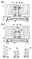
- Figures 1 and 2 illustrate a preferred embodiment according to the invention of a pressure fixing device 10 of two parts 11, 12 to each other, constituted respectively by the radiator 11 mounted on the plate d interface 12 of a housing 13 for a high density integrated circuit 14.
- the illustrated housing 13 corresponds to that described in patent application No. 87 13417 of the applicant.
- the plate 12 serves both as a support for the integrated circuit 14 and as an element for removing the heat dissipated by the integrated circuit.
- the part 12 is for example a massive copper base plate substantially square 25 millimeters on a side.
- the plate 12 is provided with an axial column 15 for fixing the finned radiator 11.
- the pressure fixing device 10 comprises a pressure device 16 in the form of a helical spring and a removable connection device composed of a washer 17, a pin 18 and a hole 19 in the column 15 for the pin 18.
- the spring 16 is made of a shape memory material.
- Figures 3A, 3B and 3C illustrate the characteristics of the spring 16 used for the fixing device 10.
- the spring 16 is made of titanium and nickel.
- FIG. 3A illustrates the spring in its stable, freely deployed state, corresponding to the austenitic phase of the shape memory material.
- FIG. 3B illustrates the retracted spring 16, in its martensitic phase.
- the material chosen had a transition temperature Ms of 213 K.
- the state of the spring 16 illustrated in FIG. 3B corresponds to a temperature below 213 K
- the freely deployed state illustrated in FIG. 3A corresponds to a temperature above 213 K, and less than 423 K which is the maximum temperature for obtaining shape memory.
- FIG. 3C illustrates the state of the spring 16 compressed in its austenitic phase to exert the predetermined pressure when it is mounted in the fixing device 10 as shown in FIG. 1.
- the radiator 11 is threaded around the column 15 until it comes into contact with the plate 12 of the housing 13.
- the spring 16 in its state shown in FIG. 3A is then placed coaxially with the column 15.
- the spring 16 is then subjected to a temperature below its transition temperature Ms to put it in its martensitic phase and obtain its retracted state as shown in Figures 2 and 3B.
- the low temperature can be obtained, for example, from a cryogenic aerosol can which offers the advantage of convenience of use, transport and handling.
- the washer 17 is placed on the spring 16 and the pin 18 is introduced into the hole 19 of the column 15. This introduction takes place naturally without effort and easily.
- the pressure device 16 can be complex and use various pressure elements in various forms. It may suffice, depending on their arrangement, that at least one of the pressure elements is made of a shape memory material. Given the great variety of shape memory materials, the pressure device can have a shape other than that illustrated and have completely different characteristics, provided that it fulfills a function similar to that described.
- the removable connection device can obviously be any, provided that it allows the release of the pressure device 16 from its compressed state when the two parts 11 and 12 are disassembled. The washer could thus be replaced 17 and the pin 18 by a retractable ring for example.
Landscapes
- Cooling Or The Like Of Electrical Apparatus (AREA)
- Cooling Or The Like Of Semiconductors Or Solid State Devices (AREA)
- Connection Of Plates (AREA)
- Snaps, Bayonet Connections, Set Pins, And Snap Rings (AREA)
- Automatic Assembly (AREA)
- Insertion Pins And Rivets (AREA)
Claims (4)
- Befestigungsvorrichtung (10), um zwei übereinanderliegende Teile (11, 12) mittels eines Stabes (15), der an einem der Teile befestigt ist, und einer Druckvorrichtung (16), die sich am anderen Teil sowie an einer abnehmbaren Verbindungsvorrichtung (17, 18, 19) des Stabes abstützt, aneinander zu befestigen, dadurch gekennzeichnet, daß die Druckvorrichtung ein Element mit Formerinnerungsvermögen beinhaltet, das sich in einem zurückgezogenen Zustand befinden kann, und daß die Verbindungsvorrichtung vom Stab gelöst werden kann, wenn das Element mit Formerinnerungsvermögen sich in seinem zurückgezogenen Zustand befindet.
- Vorrichtung nach Anspruch 1, dadurch gekennzeichnet, daß die Verbindungsvorrichtung einen Stift (18) enthält, der den Stab (15) durchquert, und eine Scheibe (17), die auf den Stab aufgesteckt ist.
- Vorrichtung nach Anspruch 1 oder 2, dadurch gekennzeichnet, daß die Druckvorrichtung (16) eine den Stab umgebende Schraubenfeder ist, die aus einem Material mit Formerinnerungsvermögen besteht.
- Gehäuse (13) einer hochintegrierten Schaltung (14), mit einem Kühlkörper (11), einer Zwischenplatte (12), die die integrierte Schaltung trägt, sowie einer Befestigungsvorrichtung nach einem der Ansprüche 1 bis 3 zum Befestigen des Kühlkörpers an der Zwischenplatte.
Applications Claiming Priority (2)
| Application Number | Priority Date | Filing Date | Title |
|---|---|---|---|
| FR8803675A FR2629153B1 (fr) | 1988-03-22 | 1988-03-22 | Dispositif de fixation a pression de deux pieces l'une a l'autre |
| FR8803675 | 1988-03-22 |
Publications (2)
| Publication Number | Publication Date |
|---|---|
| EP0334708A1 EP0334708A1 (de) | 1989-09-27 |
| EP0334708B1 true EP0334708B1 (de) | 1994-05-25 |
Family
ID=9364482
Family Applications (1)
| Application Number | Title | Priority Date | Filing Date |
|---|---|---|---|
| EP89400664A Expired - Lifetime EP0334708B1 (de) | 1988-03-22 | 1989-03-10 | Anordnung zur Befestigung von zwei Stücken durch Anpressen und Gehäuse für ein integriertes Schaltungsbauelement mit dieser Anordnung |
Country Status (5)
| Country | Link |
|---|---|
| US (1) | US5010949A (de) |
| EP (1) | EP0334708B1 (de) |
| JP (1) | JPH0682939B2 (de) |
| DE (1) | DE68915471T2 (de) |
| FR (1) | FR2629153B1 (de) |
Families Citing this family (41)
| Publication number | Priority date | Publication date | Assignee | Title |
|---|---|---|---|---|
| WO1993017536A1 (en) * | 1992-02-28 | 1993-09-02 | Aavid Engineering, Inc. | Self-locking heat sinks for surface mount devices |
| DE4226816C2 (de) * | 1992-08-13 | 1996-08-22 | Licentia Gmbh | Vorrichtung zur Wärmeableitung aus einem Gehäuse einer integrierten Schaltung |
| US5868013A (en) * | 1993-06-01 | 1999-02-09 | Nitinol Technologies, Inc. | High security lock |
| US5386870A (en) * | 1993-07-12 | 1995-02-07 | University Of Chicago | High thermal conductivity connector having high electrical isolation |
| WO1995015442A1 (en) * | 1993-11-30 | 1995-06-08 | Kvaerner Tamturbine Oy | Pre-tensioning device for fastening elements and method for pre-tensioning a fastening element |
| FI93987C (fi) * | 1993-11-30 | 1995-06-26 | Kvaerner Tamturbine Oy | Aluslaatta ja menetelmä esijännityksen suorittamiseksi |
| USD361317S (en) | 1994-05-26 | 1995-08-15 | Wakefield Engineering, Inc. | Heat sink device |
| US5586005A (en) * | 1995-03-16 | 1996-12-17 | International Business Machines Corporation | Removable heat sink assembly for a chip package |
| US5581441A (en) * | 1995-06-07 | 1996-12-03 | At&T Global Information Solutions Company | Electrically-operated heat exchanger release mechanism |
| EP0750341A1 (de) * | 1995-06-19 | 1996-12-27 | BULL HN INFORMATION SYSTEMS ITALIA S.p.A. | Lösbar verbundene Wärmesenke für VLSI-Schaltung |
| US5847452A (en) * | 1997-06-30 | 1998-12-08 | Sun Microsystems, Inc. | Post mounted heat sink method and apparatus |
| US6126371A (en) * | 1999-04-05 | 2000-10-03 | Lockheed Martin Corporation | Shape memory metal alloy preload attenuation device |
| US6381844B1 (en) * | 1999-12-15 | 2002-05-07 | Sun Microsystems, Inc. | Method for thermally connecting a heat sink to a cabinet |
| US6169659B1 (en) * | 2000-02-04 | 2001-01-02 | Silicon Graphics, Inc. | Metered force single point heatsink attach mechanism |
| US6692360B2 (en) | 2000-07-21 | 2004-02-17 | Konami Corporation | Game system, commercial game apparatus, network game apparatus, client device, and recording medium |
| JP2002035428A (ja) | 2000-07-21 | 2002-02-05 | Konami Co Ltd | ゲームシステム、ネットワークゲーム装置、ゲーム装置、クライアント装置、記録媒体 |
| US6445588B1 (en) * | 2001-01-02 | 2002-09-03 | Motorola, Inc. | Apparatus and method for securing a printed circuit board to a base plate |
| US6557675B2 (en) * | 2001-07-31 | 2003-05-06 | Compaq Information Technologies Group, L.P. | Tunable vibration damper for processor packages |
| US6829143B2 (en) * | 2002-09-20 | 2004-12-07 | Intel Corporation | Heatsink retention apparatus |
| CA2509902A1 (en) * | 2002-12-13 | 2004-07-01 | Aurelium Biopharma Inc. | Nucleophosmin directed diagnostics and therapeutics for multidrug resistant neoplastic disease |
| US7242583B2 (en) * | 2002-12-16 | 2007-07-10 | Paricon Technologies, Corporation | System for loading a heat sink mechanism independently of clamping load on electrical device |
| US7480143B2 (en) * | 2003-04-21 | 2009-01-20 | Hewlett-Packard Development Company, L.P. | Variable-gap thermal-interface device |
| US6798663B1 (en) * | 2003-04-21 | 2004-09-28 | Hewlett Packard Development Company, L.P. | Heat sink hold-down with fan-module attach location |
| US20040226688A1 (en) * | 2003-04-30 | 2004-11-18 | Arthur Fong | Application specific apparatus for dissipating heat from multiple electronic components |
| US20050244245A1 (en) * | 2004-04-30 | 2005-11-03 | Anatoly Efremov | Method and devices to limit a creep of mechanical fasteners |
| US7080989B2 (en) * | 2004-06-10 | 2006-07-25 | Sun Microsystems, Inc. | Memory metal springs for heatsink attachments |
| FR2880192B1 (fr) * | 2004-12-23 | 2007-06-01 | Sagem | Systeme a deux etats pour la regulation thermique d'un dispositif electronique |
| US20070097648A1 (en) * | 2005-11-01 | 2007-05-03 | Kevin Xu | Method and apparatus for establishing optimal thermal contact between opposing surfaces |
| US20070169928A1 (en) * | 2006-01-26 | 2007-07-26 | Dayan Richard A | Heat sink for controlling dissipation of a thermal load |
| US20080079129A1 (en) * | 2006-09-29 | 2008-04-03 | Shankar Ganapathysubramanian | Shape memory based mechanical enabling mechanism |
| DE102009002992B4 (de) * | 2009-05-11 | 2014-10-30 | Infineon Technologies Ag | Leistungshalbleitermodulanordnung mit eindeutig und verdrehsicher auf einem Kühlkörper montierbarem Leistungshalbleitermodul und Montageverfahren |
| DE102012208767A1 (de) | 2011-06-17 | 2012-12-20 | Robert Bosch Gmbh | Elektronische Schaltungsanordnung mit Verlustwärme abgebenden Komponenten |
| US8929077B2 (en) * | 2012-01-02 | 2015-01-06 | Tem Products Inc. | Thermal connector |
| US10880986B2 (en) * | 2019-03-29 | 2020-12-29 | Intel Corporation | Activate loading mechanism |
| US11175100B2 (en) * | 2019-05-07 | 2021-11-16 | International Business Machines Corporation | Heat sinks using memory shaping materials |
| US11420755B2 (en) | 2019-08-08 | 2022-08-23 | General Electric Company | Shape memory alloy isolator for a gas turbine engine |
| US11019751B2 (en) | 2020-03-27 | 2021-05-25 | Intel Corporation | Activate loading mechanism |
| US11828235B2 (en) | 2020-12-08 | 2023-11-28 | General Electric Company | Gearbox for a gas turbine engine utilizing shape memory alloy dampers |
| US11758690B2 (en) * | 2021-06-18 | 2023-09-12 | Nanning Fulian Fugui Precision Industrial Co., Ltd. | Heat-dissipation device allowing easy detachment from heat-generating component |
| CN113441933A (zh) * | 2021-07-14 | 2021-09-28 | 浙江亚美力新能源科技有限公司 | 自动上料汽车散热器芯体自动装配设备 |
| US11991864B2 (en) * | 2022-03-16 | 2024-05-21 | Google Llc | Load vectoring heat sink |
Family Cites Families (8)
| Publication number | Priority date | Publication date | Assignee | Title |
|---|---|---|---|---|
| SU114834A1 (ru) * | 1957-05-20 | 1957-11-30 | А.И. Зеленов | Электрод дл сварки чугуна |
| FR2306783A2 (fr) * | 1973-10-09 | 1976-11-05 | Raychem Corp | Dispositifs susceptibles de reprise thermique et leur application au raccordement de substrats |
| CH592961A5 (de) * | 1975-09-23 | 1977-11-15 | Bbc Brown Boveri & Cie | |
| JPS57203111A (en) * | 1981-06-09 | 1982-12-13 | Toshiba Corp | Controller for amount of heat dissipation |
| JPS59225548A (ja) * | 1983-06-07 | 1984-12-18 | Komatsu Ltd | 放熱装置 |
| JPS6112277U (ja) * | 1984-06-28 | 1986-01-24 | 富士通株式会社 | フラツトリ−ドパツケ−ジ型電子部品の実装構造 |
| JPS63102143U (de) * | 1986-12-23 | 1988-07-02 | ||
| JPS63195748A (ja) * | 1987-02-09 | 1988-08-12 | Mitsubishi Electric Corp | 計算機システムのメモリマツプド制御装置 |
-
1988
- 1988-03-22 FR FR8803675A patent/FR2629153B1/fr not_active Expired - Lifetime
-
1989
- 1989-03-10 DE DE68915471T patent/DE68915471T2/de not_active Expired - Fee Related
- 1989-03-10 EP EP89400664A patent/EP0334708B1/de not_active Expired - Lifetime
- 1989-03-20 US US07/325,763 patent/US5010949A/en not_active Expired - Fee Related
- 1989-03-22 JP JP1070307A patent/JPH0682939B2/ja not_active Expired - Lifetime
Also Published As
| Publication number | Publication date |
|---|---|
| FR2629153A1 (fr) | 1989-09-29 |
| DE68915471T2 (de) | 1994-11-03 |
| DE68915471D1 (de) | 1994-06-30 |
| FR2629153B1 (fr) | 1990-05-04 |
| JPH0682939B2 (ja) | 1994-10-19 |
| EP0334708A1 (de) | 1989-09-27 |
| US5010949A (en) | 1991-04-30 |
| JPH0271594A (ja) | 1990-03-12 |
Similar Documents
| Publication | Publication Date | Title |
|---|---|---|
| EP0334708A1 (de) | Anordnung zur Befestigung von zwei Stücken durch Anpressen und Gehäuse für ein integriertes Schaltungsbauelement mit dieser Anordnung | |
| EP0974179B1 (de) | Vorrichtung zum verbinden elektrischer kabel | |
| EP2483585B1 (de) | Vorrichtung zur befestigung eines länglichen elements auf einem turbinenmotorgehäuse | |
| EP0558359A1 (de) | Vorrichtung zur Befestigung eines elektronischen Bauteils an die Seite eines Wärmeableiters | |
| FR2586510A1 (fr) | Module a semi-conducteurs ayant une grande aptitude au refroidissement et procede pour sa fabrication | |
| EP0169117A1 (de) | Drehanoden-Röntgenröhre und Verfahren zur Befestigung einer Drehanode auf einer Trägerachse | |
| EP0593330B1 (de) | 3D-Verbindungsverfahren für Gehäuse von elektronischen Bauteilen und resultierendes 3D-Bauteil | |
| FR2755303A1 (fr) | Antenne de champ magnetique blindee en circuit imprime | |
| FR2723410A1 (fr) | Plaquette de frein avec temoin d'usure | |
| FR2608840A1 (fr) | Structure de refroidissement pour circuits integres | |
| FR2559956A1 (fr) | Boitier en metal et resine pour dispositif a semi-conducteur, susceptible d'etre fixe sur un dissipateur non parfaitement plan, et son procede de fabrication | |
| EP1692428B1 (de) | Befestigungsvorrichtung für feuerdetektionssystem | |
| CA2849049A1 (fr) | Composant electronique de puissance bobine comportant un support de drainage thermique | |
| FR2676871A1 (fr) | Structure pour la fixation d'aimants permanents dans un moteur. | |
| FR2701340A1 (fr) | Procédé de réalisation d'un circuit de distribution de signaux électriques, circuit de distribution obtenu et moteur piézoélectrique comportant un tel circuit. | |
| FR2880192A1 (fr) | Systeme a deux etats pour la regulation thermique d'un dispositif electronique | |
| EP3540359B1 (de) | Vorrichtung zur wärmeleitung und entsprechendes wärmeableitungssystem | |
| CA2849048A1 (fr) | Composant electronique de puissance bobine comportant un support de drainage thermique | |
| FR2561034A1 (fr) | Condensateur a dielectrique film plastique comportant deux electrodes de sortie pourvues de conducteurs aptes a etre soudes sur circuit imprime | |
| FR2811409A1 (fr) | Structure de support avec des etats alternatifs de grande resistance ou de faible conductivite thermique et entretoises de liaison comportant une telle structure | |
| EP0443483B1 (de) | Lötverfahren für die Befestigung eines Elementes, wie z.B. eines hybriden Schaltkreissubstrats auf einer wärmeableitenden Unterlage | |
| FR2617334A1 (fr) | Dissipateur thermique pour circuit integre | |
| BE494693A (de) | ||
| BE465153A (de) | ||
| CH697543B1 (fr) | Dispositif d'articulation pour attacher à pivotement au moins deux maillons d'un bracelet. |
Legal Events
| Date | Code | Title | Description |
|---|---|---|---|
| PUAI | Public reference made under article 153(3) epc to a published international application that has entered the european phase |
Free format text: ORIGINAL CODE: 0009012 |
|
| AK | Designated contracting states |
Kind code of ref document: A1 Designated state(s): DE FR GB IT NL SE |
|
| 17P | Request for examination filed |
Effective date: 19891014 |
|
| 17Q | First examination report despatched |
Effective date: 19920525 |
|
| RAP3 | Party data changed (applicant data changed or rights of an application transferred) |
Owner name: BULL S.A. |
|
| GRAA | (expected) grant |
Free format text: ORIGINAL CODE: 0009210 |
|
| AK | Designated contracting states |
Kind code of ref document: B1 Designated state(s): DE FR GB IT NL SE |
|
| REF | Corresponds to: |
Ref document number: 68915471 Country of ref document: DE Date of ref document: 19940630 |
|
| GBT | Gb: translation of ep patent filed (gb section 77(6)(a)/1977) |
Effective date: 19940602 |
|
| ITF | It: translation for a ep patent filed | ||
| EAL | Se: european patent in force in sweden |
Ref document number: 89400664.2 |
|
| PLBE | No opposition filed within time limit |
Free format text: ORIGINAL CODE: 0009261 |
|
| STAA | Information on the status of an ep patent application or granted ep patent |
Free format text: STATUS: NO OPPOSITION FILED WITHIN TIME LIMIT |
|
| 26N | No opposition filed | ||
| PGFP | Annual fee paid to national office [announced via postgrant information from national office to epo] |
Ref country code: SE Payment date: 19960208 Year of fee payment: 8 |
|
| PGFP | Annual fee paid to national office [announced via postgrant information from national office to epo] |
Ref country code: FR Payment date: 19960209 Year of fee payment: 8 |
|
| PGFP | Annual fee paid to national office [announced via postgrant information from national office to epo] |
Ref country code: GB Payment date: 19960311 Year of fee payment: 8 |
|
| PGFP | Annual fee paid to national office [announced via postgrant information from national office to epo] |
Ref country code: NL Payment date: 19960331 Year of fee payment: 8 |
|
| PGFP | Annual fee paid to national office [announced via postgrant information from national office to epo] |
Ref country code: DE Payment date: 19960508 Year of fee payment: 8 |
|
| PG25 | Lapsed in a contracting state [announced via postgrant information from national office to epo] |
Ref country code: GB Effective date: 19970310 |
|
| PG25 | Lapsed in a contracting state [announced via postgrant information from national office to epo] |
Ref country code: SE Effective date: 19970311 |
|
| PG25 | Lapsed in a contracting state [announced via postgrant information from national office to epo] |
Ref country code: NL Effective date: 19971001 |
|
| GBPC | Gb: european patent ceased through non-payment of renewal fee |
Effective date: 19970310 |
|
| PG25 | Lapsed in a contracting state [announced via postgrant information from national office to epo] |
Ref country code: FR Free format text: LAPSE BECAUSE OF NON-PAYMENT OF DUE FEES Effective date: 19971128 |
|
| NLV4 | Nl: lapsed or anulled due to non-payment of the annual fee |
Effective date: 19971001 |
|
| PG25 | Lapsed in a contracting state [announced via postgrant information from national office to epo] |
Ref country code: DE Effective date: 19971202 |
|
| EUG | Se: european patent has lapsed |
Ref document number: 89400664.2 |
|
| REG | Reference to a national code |
Ref country code: FR Ref legal event code: ST |
|
| PG25 | Lapsed in a contracting state [announced via postgrant information from national office to epo] |
Ref country code: IT Free format text: LAPSE BECAUSE OF NON-PAYMENT OF DUE FEES;WARNING: LAPSES OF ITALIAN PATENTS WITH EFFECTIVE DATE BEFORE 2007 MAY HAVE OCCURRED AT ANY TIME BEFORE 2007. THE CORRECT EFFECTIVE DATE MAY BE DIFFERENT FROM THE ONE RECORDED. Effective date: 20050310 |