EP0334460B1 - Förderboden mit mehreren parallelen Förderbalken für Kompostieranlagen - Google Patents
Förderboden mit mehreren parallelen Förderbalken für Kompostieranlagen Download PDFInfo
- Publication number
- EP0334460B1 EP0334460B1 EP89200770A EP89200770A EP0334460B1 EP 0334460 B1 EP0334460 B1 EP 0334460B1 EP 89200770 A EP89200770 A EP 89200770A EP 89200770 A EP89200770 A EP 89200770A EP 0334460 B1 EP0334460 B1 EP 0334460B1
- Authority
- EP
- European Patent Office
- Prior art keywords
- beams
- floor
- load
- air
- conveying
- Prior art date
- Legal status (The legal status is an assumption and is not a legal conclusion. Google has not performed a legal analysis and makes no representation as to the accuracy of the status listed.)
- Expired - Lifetime
Links
Images


Classifications
-
- B—PERFORMING OPERATIONS; TRANSPORTING
- B65—CONVEYING; PACKING; STORING; HANDLING THIN OR FILAMENTARY MATERIAL
- B65G—TRANSPORT OR STORAGE DEVICES, e.g. CONVEYORS FOR LOADING OR TIPPING, SHOP CONVEYOR SYSTEMS OR PNEUMATIC TUBE CONVEYORS
- B65G25/00—Conveyors comprising a cyclically-moving, e.g. reciprocating, carrier or impeller which is disengaged from the load during the return part of its movement
- B65G25/04—Conveyors comprising a cyclically-moving, e.g. reciprocating, carrier or impeller which is disengaged from the load during the return part of its movement the carrier or impeller having identical forward and return paths of movement, e.g. reciprocating conveyors
- B65G25/06—Conveyors comprising a cyclically-moving, e.g. reciprocating, carrier or impeller which is disengaged from the load during the return part of its movement the carrier or impeller having identical forward and return paths of movement, e.g. reciprocating conveyors having carriers, e.g. belts
- B65G25/065—Reciprocating floor conveyors
Definitions
- the invention relates to a a load conveying floor, comprising a plurality of floor beams positioned side by side and parallel to the conveying direction, said beams being supported and mounted for a longitudinal sliding movement on mutual spaced cross beams, said floor being arranged in groups of fixedly interconnected beams that are evenly distributed across the floor width, each group of floor beams being - below floor level - associated with a drive means of the piston cylinder type which has one end connected to a fixed point of the floor construction whereas its other end engages the means that interconnects the beams of the respective group, the drive means for all of the groups being operable to either move all of the groups simultaneously from retracted end positions into forward end positions, thereby conveying the load in the conveying direction, or moving the drive means of the respective groups one after the other from said forward end positions into the individual retracted end positions and thereby keeping the load stationary.
- Such a floor is known from EP 0 085 736.
- This well-known floor constitutes the floor of a load carrying truck.
- the movable floor beams are provided - on their lower side - with bushings which slide on stationary slide rods.
- a load carrying floor of the above mentioned type is provided, which is characterized in that each of said floor beams is supported on each of said cross beams with the intermediary of a roller extending with its axis parallel to said cross beams, and that the piston-cylinder devices have their cilinder ends fastened to a side face of one of said cross beams whereas the piston rod ends of said devices are directly connected to the interconnecting means of the respective groups, said cross beams constituting the floor supporting beams of a stationary building adapted for use in the conversion of organic waste material into compost, said building comprising means including air inlet and outlet openings arranged to have an air stream pass through the load of waste material on said floor.
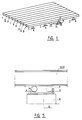
- the floor shown in fig. 1 comprises longitudinally extending parallel beams of which the beams designated by 1 constitute one group, the beams 2 a second group and the beams 3 a third group.
- the embodiment shows three sets of each time a beam 1, 2 and 3 or three beams in group 1, three beams in group 2 and three beams in group 3.
- the numbers may be different, and each group may also comprise a single wide beam.
- each group i.e. the group of beams 1 and so on
- one drive is associated.
- This comprises in the embodiment shown a piston-cylinder device 4, one end of which is connected to a fixed point 5 of one of the beams and through cross-connections to all beams of the group, whereas the other end is connected to a stationary support structure, e.g. comprising cross-beams 6 supported by the floor 8 below the conveyor floor, e.g. a concrete foundation.
- This last mentioned floor may be the floor of a stationary building.
- each beam, so each of the beams 1, 2, 3, is supported on the crossbeam 6 by means of a plurality of rolls 7.
- the operation is as follows: when a group of beams, e.g. the beams 3, are moved in forward direction by the associated piston-cylinder device 4, a load (not shown) placed on the floor, remains in rest. The same applies if the drive of the beams 2 is thereafter actuated and also thereafter the drive of the beams 1. For the force imparted by a single group of beams through the friction on the load is not sufficient for moving the load.
- the stroke of the drive cylinders may be e.g. 15 cm, then the distance whereby the rolls move along the cross beams 6 is one half thereof, i.e. 7.5 cm. Also a stroke of 20 cm and more is possible. This applies to rolls which are freely supported, i.e. move on the support structure and below the conveyor floor beams. If stationary rolls would be provided in a support member on the building floor, only the conveyor floor moves.
- cross beams 6 are provided at the position of the rolls 7 with end flanges 9 so that the rolls remain enclosed by their support member.
- the beams are provided, in addition to the support rolls 7, with side rolls 10, which are rotatable around vertical shafts (see fig. 4).
- side rolls 10 which are rotatable around vertical shafts (see fig. 4).
- the beams are warped or warp said rolls may enter into engagement with the beams which therefore are provided with side flanges 8 along which the roll 10 may roll. Thereby the friction is further reduced.
- the beams are shown to the left in fig. 4 as being I-sections, to the right in fig. 4 as being solid concrete beams. In that case the rolls 10 are rotatably received in the side wall of said beams.
- Fig. 5 shows the above mentioned embodiment in which a carrier member for the rolls 7, here indicated by 12, has a hollow shape extending in the direction of movement of the beams.
- the lower side of the beam 1, 2 or 3 may have a reversed hollow shape at the position of the roll support, whereas then the support structure below the roll extends in a straight line. The purpose is in both cases to permit the beam during its movement to lower somewhat, so that its upper side releases the load.
- the backward driving stroke for the beams in which the load is taken along all beams are lowered simultaneously and thereby also the load, so that in that case the contact with the load is not lost.
- Fig. 6 and 6A show another embodiment in which the rolls for each group are rolls 13, extending along the full width of the floor.
- actuatable lifting devices 14 are provided which are only schematically shown in fig. 6.
- Said lifting devices may also be provided per group of beams instead of per beam.
- the lifting devices may be pneumatic or hydraulic piston cylinder devices, push rods or also air hoses.
- the rolls such as the rolls 7, may comprise, apart from a couple of rolls, groups of rolls combined into a so-called roller vehicle, the rolls of which may constitute railway vehicle wheels.
- the friction due to the rolling movement for shifting the floor will be only about 1 - 5% of the vertical floor loading.
- the friction resistance against moving the load along the beam or group of beams during mutual shifting of the beams becomes practically zero due to the release from the load.
- the conveyor floor according to the invention is used as a conveyor means for waste when aerobically converting organic waste to compost.
- Fig. 7 shows that some beams of, in this case, concrete beams 1, 2, 3 are hollow, said hollow beams being equally spaced along the beams and are connected per group to a main conduit 16, provided below the floor 6, by means of flexible houses.
- a main conduit 16 provided below the floor 6, by means of flexible houses.
- air may be blown into the beams through pumps (not shown), said air leaving the beams through apertures 17 provided in the upper wall.
- Organic waste 18, to be converted to compost, is supported by the floor.
- the floor is provided in a completely closed building and the air leaving the material 18 is sucked off through filters (not shown) into the atmosphere. Thereby the spreading of stench is avoided.
- FIG. 8 shows schematically another possibility in which air channels 19 have been provided on certain of the floor beams, said channels being likewise connected to the branch-off hoses 15 at their lower ends, said hoses being connected to the main conduit 16.
- the air channels 19 have a restricted nozzle at their upper sides, over which a cap 21 is provided such that the exit apertures are directed laterally while the cap prevents blocking of the nozzle by the waste.
- the arrows 22 indicate the exit and the arrows 22a the inflow of the air from and into the waste mass 18.
- the height of the roof of the building over the beams may be about 2.5 m. This space may be filled almost completely with waste material. Thereby there is only a small unused air space, i.e. a volume of the building in which no waste is present.
- the supply and delivery of the material may take place at the same end of the building, which facilitates the transport.
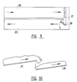
- the floor portion 25 according to fig. 10 conveys to the right, the floor portion 26 to the left. Between said portions there is provided a conveyor belt 27.
- a conveyor belt 28 which is moved to and fro provides for spreading the material supplied by the belt 27 over the second floor portion 26. Thereby and by the transport by the conveyor belts the material is stirred and thereby aerated.
- Fig. 11 shows a floor having adjacent obliquelike portions 29 and 30 whereby the material drops from the end of portion 29 onto the initial part of portion 30 and is aerated thereby. Due to the small friction resistance to movement of the floor according to the invention, large floor loads, large cantilevered spans and large floor dimensions are permitted.
- the joints between the floor beams should be completely sealed since otherwise so called false air is sucked through the joints, which air then does not pass the heap of waste material.
Landscapes
- Engineering & Computer Science (AREA)
- Mechanical Engineering (AREA)
- Fertilizers (AREA)
- Processing Of Solid Wastes (AREA)
- Fertilizing (AREA)
Claims (4)
- Last-fördernder Boden mit einer Vielzahl von nebeneinander und parallel zur Förderrichtung angeordneten Balken (1, 2, 3), welche in der Längsrichtung verschieblich auf im Abstand voneinander angeordneten Querbalken (6) aufliegen, welcher Boden in Gruppen von untereinander fest verbundenen, gleichmässig über die Bodenbreite verteilt liegenden Balken ausgelegt ist, wobei jede Gruppe von Bodenbalken - unter der Bodenebene - mit einem Antriebsmittel vom Kolben-Zylindertyp verbunden ist, dessen eine Ende an einem festen Punkt der Bodenanordnung angelenkt ist und dessen andere Ende mit dem die Balken der betreffenden Gruppe miteinander verbindenden Mittel verbunden ist, wobei die Antriebsmittel für sämtliche Gruppen derart steuerbar sind, dass entweder alle Gruppen zugleicherzeit aus den zurückgezogenen Endlagen in die vorderen Endlagen bewegt werden, wobei der Last in der Förderrichtung mitgenommen wird, oder die Antriebsmittel der betreffenden Gruppen nacheinander aus den genannten vorderen Lagen in die individuelle zurückgezogenen Endlagen bewegt werden, wobei der Last stillstehen bleibt, dadurch gekennzeichnet, dass jeder Bodenbalken auf jeder Querbalken mittels einer Rolle (7), deren Achse sich parallel zu den Querbalken erstreckt, aufgelegt ist und dass die Zylinderenden der Kolben-Zylindervorrichtungen an einer Seitenfläche (9) eines der Querbalken befestigt sind, während die Kolbenstangenenden jener Vorrichtungen unmittelbar mit den die Balken der betreffenden Gruppen untereinander verbindenden Mitteln verbunden sind, welche Querbalken die Stützbalken eines für die Umwandlung von Müll in Kompost eingerichteten Gebäudes bilden, bei welchem Gebäude Mittel, sowie Lufteinlassöffnungen und Luftauslassöffnungen vorgesehen sind zur Erzeugung eines Luftstromes durch die Müllmenge auf dem genannten Boden hindurch gehenden Luftstromes.
- Last-fördernder Boden nach Anspruch 1, dadurch gekennzeichnet, dass Luftkanäle mit Austrittsöffnungen (17) regelmässig verteilt in den Baulken (1, 2, 3) des Bodens angeordnet sind, welche Kanäle an einem biegsamen Schlauch (15) angeschlossen sind, welcher mit einer Luft-Zufuhrleitung (16) verbunden ist.
- Boden nach Anspruch 2, dadurch gekennzeichnet, dass die Anstrittsöffunngen (20) in von einigen der Baulken (1, 2, 3) aufstenenden und sich in der Längsrichtung dieser Balken erstreckenden Luftkanäle (19) vorgesehen sind, in der Weise, dass die Luft im Zentrum des auf den Balken liegenden Mülls (18) geblasen bezw. aus dem Zentrum angesaugt wird.
- Last-fördernder Boden nach einem der vorangehenden Ansprüche, dadurch gekennzeichnet, dass auf den Querbalken (6) eine Auflage für eine Rolle (7) vorgesehen ist, welche Auflage eine konkav geformte Oberfläche aufweist, deren tiefster Punkt (12) in der Längsmitte liegt.
Applications Claiming Priority (2)
| Application Number | Priority Date | Filing Date | Title |
|---|---|---|---|
| NL8800728A NL8800728A (nl) | 1988-03-23 | 1988-03-23 | Uit onderling verschuifbare, evenwijdige balken bestaande transportvloer, in het bijzonder voor een afvalcomposteringsinstallatie. |
| NL8800728 | 1988-03-23 |
Publications (3)
| Publication Number | Publication Date |
|---|---|
| EP0334460A2 EP0334460A2 (de) | 1989-09-27 |
| EP0334460A3 EP0334460A3 (en) | 1990-10-10 |
| EP0334460B1 true EP0334460B1 (de) | 1994-07-13 |
Family
ID=19851985
Family Applications (1)
| Application Number | Title | Priority Date | Filing Date |
|---|---|---|---|
| EP89200770A Expired - Lifetime EP0334460B1 (de) | 1988-03-23 | 1989-03-23 | Förderboden mit mehreren parallelen Förderbalken für Kompostieranlagen |
Country Status (5)
| Country | Link |
|---|---|
| EP (1) | EP0334460B1 (de) |
| AT (1) | ATE108408T1 (de) |
| DE (1) | DE68916672T2 (de) |
| ES (1) | ES2055781T3 (de) |
| NL (1) | NL8800728A (de) |
Cited By (2)
| Publication number | Priority date | Publication date | Assignee | Title |
|---|---|---|---|---|
| KR20170039199A (ko) * | 2014-07-22 | 2017-04-10 | 에이엠비 | 열 입력에 의한 제품의 연속처리를 위한 시스템 |
| WO2023080779A1 (en) * | 2021-11-02 | 2023-05-11 | Valoriworld B.V. | Dynamic active loading and aeration floor for composting organic material in a closed mobile or stationary reactor |
Families Citing this family (5)
| Publication number | Priority date | Publication date | Assignee | Title |
|---|---|---|---|---|
| FR2661899B1 (fr) * | 1990-05-09 | 1995-08-11 | Marceau Gilbert | Transporteur a barres paralleles. |
| WO1992000904A1 (de) * | 1990-07-10 | 1992-01-23 | Georg Hirmann | Vorrichtung zum verschieben von lasten und kräften |
| CA2102524A1 (fr) * | 1991-05-07 | 1992-11-08 | Gilbert Marceau | Appareil transporteur a barres paralleles |
| NL9300800A (nl) * | 1993-05-10 | 1994-12-01 | Pacques Bv | Transportinrichting in de vorm van een bewegende vloer. |
| LU503128B1 (en) * | 2022-12-02 | 2024-06-03 | Wurth Paul Sa | Reciprocating Floor |
Family Cites Families (6)
| Publication number | Priority date | Publication date | Assignee | Title |
|---|---|---|---|---|
| FR2092724A1 (de) * | 1970-06-12 | 1972-01-28 | Forder Ag | |
| DE2150647A1 (de) * | 1970-10-12 | 1972-04-13 | Ingersoll Rand Co | Vorrichtung zum Foerdern von Werkstuecken |
| US4071137A (en) * | 1976-12-13 | 1978-01-31 | Auburn Foundry, Inc. | Walking beam conveyor apparatus and method of operating the same |
| US4474285A (en) * | 1982-02-08 | 1984-10-02 | Foster Raymond K | Drive unit mount for reciprocating floor conveyor |
| DE3277965D1 (en) * | 1982-04-30 | 1988-02-18 | Koyo Chuki Co | A foundry pouring station table |
| US4798802A (en) * | 1987-07-28 | 1989-01-17 | Ryan Richard M | Method for accelerating composting of organic matter and composting reactor therefor |
-
1988
- 1988-03-23 NL NL8800728A patent/NL8800728A/nl not_active Application Discontinuation
-
1989
- 1989-03-23 DE DE68916672T patent/DE68916672T2/de not_active Expired - Fee Related
- 1989-03-23 ES ES89200770T patent/ES2055781T3/es not_active Expired - Lifetime
- 1989-03-23 AT AT89200770T patent/ATE108408T1/de not_active IP Right Cessation
- 1989-03-23 EP EP89200770A patent/EP0334460B1/de not_active Expired - Lifetime
Cited By (3)
| Publication number | Priority date | Publication date | Assignee | Title |
|---|---|---|---|---|
| KR20170039199A (ko) * | 2014-07-22 | 2017-04-10 | 에이엠비 | 열 입력에 의한 제품의 연속처리를 위한 시스템 |
| WO2023080779A1 (en) * | 2021-11-02 | 2023-05-11 | Valoriworld B.V. | Dynamic active loading and aeration floor for composting organic material in a closed mobile or stationary reactor |
| NL2029597B1 (nl) * | 2021-11-02 | 2023-06-01 | Valoriworld B V | Dynamische actieve beladings- en beluchtingsvloer voor het composteren van organisch materiaal in een gesloten mobiele of stationaire reactor. |
Also Published As
| Publication number | Publication date |
|---|---|
| NL8800728A (nl) | 1989-10-16 |
| EP0334460A2 (de) | 1989-09-27 |
| ES2055781T3 (es) | 1994-09-01 |
| DE68916672T2 (de) | 1994-11-03 |
| ATE108408T1 (de) | 1994-07-15 |
| DE68916672D1 (de) | 1994-08-18 |
| EP0334460A3 (en) | 1990-10-10 |
Similar Documents
| Publication | Publication Date | Title |
|---|---|---|
| EP0524375B1 (de) | Durchlauf-Gärschrank | |
| EP0029073B1 (de) | Warenlager zur Lagerung von Stückgütern | |
| DE3739158A1 (de) | Lagersystem mit einer foerdereinrichtung, insbesondere parksystem fuer fahrzeuge | |
| US4242024A (en) | Apparatus for palletizing sheet material | |
| US20050194234A1 (en) | Conveying apparatus and method of conveying a workpiece | |
| EP0334460B1 (de) | Förderboden mit mehreren parallelen Förderbalken für Kompostieranlagen | |
| CN210659331U (zh) | 一种建筑施工用卸料平台 | |
| US5392897A (en) | Conveyor | |
| DE2113202A1 (de) | Warenlager mit laengsverfahrbaren Transporteinheiten und vertikalen Umsetzern | |
| US4270655A (en) | Walking-beam conveyer | |
| US4866281A (en) | Irradiation plant | |
| KR970702954A (ko) | 주차장에 이용할 수 있는 이동단을 가진 모듈저장 시스템(modular storage system with movable rack, specially applicable to motor vehicles) | |
| US5271334A (en) | Cart loading equipment having reciprocating pusher and chain conveyors with sensor operated central control | |
| EP0116152A2 (de) | Vorrichtung zur Einlagerung und Entnahme von stangenförmigem Material | |
| DE4428897C2 (de) | Vorrichtung zum Fördern und Zwischenspeichern von Isolierglasscheiben | |
| DE2305792C2 (de) | Lageranlage | |
| CN214398962U (zh) | 一种商标纸捆智能码垛系统 | |
| WO1993017986A1 (en) | Installation for the temporary storage of bulk goods | |
| CN214687175U (zh) | 漏缝板生产线 | |
| CN213735029U (zh) | 育苗架取料的中转车、组合单元和组合机构 | |
| AT500227B1 (de) | Transportwagen zum ein- und auslagern von transportgut | |
| CN223117231U (zh) | 一种用于地牛搬运车上下货的提升机 | |
| AT166951B (de) | Anlage für grobkeramische Massenerzeugung, insbesondere Ziegelei | |
| US3511396A (en) | Method for loading bagged mail from a loading dock into a highway vehicle | |
| US3464571A (en) | Apparatus for loading bagged mail from a loading dock into a highway vehicle |
Legal Events
| Date | Code | Title | Description |
|---|---|---|---|
| PUAI | Public reference made under article 153(3) epc to a published international application that has entered the european phase |
Free format text: ORIGINAL CODE: 0009012 |
|
| AK | Designated contracting states |
Kind code of ref document: A2 Designated state(s): AT BE CH DE ES FR GB GR IT LI LU NL SE |
|
| PUAL | Search report despatched |
Free format text: ORIGINAL CODE: 0009013 |
|
| AK | Designated contracting states |
Kind code of ref document: A3 Designated state(s): AT BE CH DE ES FR GB GR IT LI LU NL SE |
|
| 17P | Request for examination filed |
Effective date: 19910410 |
|
| 17Q | First examination report despatched |
Effective date: 19930118 |
|
| RIN1 | Information on inventor provided before grant (corrected) |
Inventor name: RUTTE-HOEKSTRA, JETSKE |
|
| GRAA | (expected) grant |
Free format text: ORIGINAL CODE: 0009210 |
|
| RAP1 | Party data changed (applicant data changed or rights of an application transferred) |
Owner name: J.B. RUTTE B.V. |
|
| AK | Designated contracting states |
Kind code of ref document: B1 Designated state(s): AT BE CH DE ES FR GB GR IT LI LU NL SE |
|
| PG25 | Lapsed in a contracting state [announced via postgrant information from national office to epo] |
Ref country code: LI Effective date: 19940713 Ref country code: GR Free format text: LAPSE BECAUSE OF FAILURE TO SUBMIT A TRANSLATION OF THE DESCRIPTION OR TO PAY THE FEE WITHIN THE PRESCRIBED TIME-LIMIT Effective date: 19940713 Ref country code: CH Effective date: 19940713 |
|
| REF | Corresponds to: |
Ref document number: 108408 Country of ref document: AT Date of ref document: 19940715 Kind code of ref document: T |
|
| REF | Corresponds to: |
Ref document number: 68916672 Country of ref document: DE Date of ref document: 19940818 |
|
| REG | Reference to a national code |
Ref country code: ES Ref legal event code: FG2A Ref document number: 2055781 Country of ref document: ES Kind code of ref document: T3 |
|
| ITF | It: translation for a ep patent filed | ||
| REG | Reference to a national code |
Ref country code: CH Ref legal event code: PL |
|
| ET | Fr: translation filed | ||
| EAL | Se: european patent in force in sweden |
Ref document number: 89200770.9 |
|
| PG25 | Lapsed in a contracting state [announced via postgrant information from national office to epo] |
Ref country code: LU Free format text: LAPSE BECAUSE OF NON-PAYMENT OF DUE FEES Effective date: 19950331 |
|
| PLBE | No opposition filed within time limit |
Free format text: ORIGINAL CODE: 0009261 |
|
| STAA | Information on the status of an ep patent application or granted ep patent |
Free format text: STATUS: NO OPPOSITION FILED WITHIN TIME LIMIT |
|
| 26N | No opposition filed | ||
| PGFP | Annual fee paid to national office [announced via postgrant information from national office to epo] |
Ref country code: AT Payment date: 19960125 Year of fee payment: 8 |
|
| PGFP | Annual fee paid to national office [announced via postgrant information from national office to epo] |
Ref country code: ES Payment date: 19960329 Year of fee payment: 8 |
|
| PG25 | Lapsed in a contracting state [announced via postgrant information from national office to epo] |
Ref country code: AT Effective date: 19970323 |
|
| PG25 | Lapsed in a contracting state [announced via postgrant information from national office to epo] |
Ref country code: ES Free format text: LAPSE BECAUSE OF NON-PAYMENT OF DUE FEES Effective date: 19970324 |
|
| REG | Reference to a national code |
Ref country code: ES Ref legal event code: FD2A Effective date: 19990503 |
|
| REG | Reference to a national code |
Ref country code: FR Ref legal event code: ST |
|
| REG | Reference to a national code |
Ref country code: FR Ref legal event code: RN |
|
| REG | Reference to a national code |
Ref country code: FR Ref legal event code: IC |
|
| PGFP | Annual fee paid to national office [announced via postgrant information from national office to epo] |
Ref country code: GB Payment date: 20010322 Year of fee payment: 13 Ref country code: FR Payment date: 20010322 Year of fee payment: 13 |
|
| PGFP | Annual fee paid to national office [announced via postgrant information from national office to epo] |
Ref country code: SE Payment date: 20010323 Year of fee payment: 13 Ref country code: DE Payment date: 20010323 Year of fee payment: 13 Ref country code: BE Payment date: 20010323 Year of fee payment: 13 |
|
| PGFP | Annual fee paid to national office [announced via postgrant information from national office to epo] |
Ref country code: NL Payment date: 20010330 Year of fee payment: 13 |
|
| REG | Reference to a national code |
Ref country code: FR Ref legal event code: RU |
|
| REG | Reference to a national code |
Ref country code: GB Ref legal event code: IF02 |
|
| PG25 | Lapsed in a contracting state [announced via postgrant information from national office to epo] |
Ref country code: GB Free format text: LAPSE BECAUSE OF NON-PAYMENT OF DUE FEES Effective date: 20020323 |
|
| PG25 | Lapsed in a contracting state [announced via postgrant information from national office to epo] |
Ref country code: SE Free format text: LAPSE BECAUSE OF NON-PAYMENT OF DUE FEES Effective date: 20020324 |
|
| PG25 | Lapsed in a contracting state [announced via postgrant information from national office to epo] |
Ref country code: BE Free format text: LAPSE BECAUSE OF NON-PAYMENT OF DUE FEES Effective date: 20020331 |
|
| BERE | Be: lapsed |
Owner name: J.B. *RUTTE B.V. Effective date: 20020331 |
|
| PG25 | Lapsed in a contracting state [announced via postgrant information from national office to epo] |
Ref country code: NL Free format text: LAPSE BECAUSE OF NON-PAYMENT OF DUE FEES Effective date: 20021001 Ref country code: DE Free format text: LAPSE BECAUSE OF NON-PAYMENT OF DUE FEES Effective date: 20021001 |
|
| EUG | Se: european patent has lapsed |
Ref document number: 89200770.9 |
|
| GBPC | Gb: european patent ceased through non-payment of renewal fee |
Effective date: 20020323 |
|
| PG25 | Lapsed in a contracting state [announced via postgrant information from national office to epo] |
Ref country code: FR Free format text: LAPSE BECAUSE OF NON-PAYMENT OF DUE FEES Effective date: 20021129 |
|
| NLV4 | Nl: lapsed or anulled due to non-payment of the annual fee |
Effective date: 20021001 |
|
| REG | Reference to a national code |
Ref country code: FR Ref legal event code: ST |
|
| PG25 | Lapsed in a contracting state [announced via postgrant information from national office to epo] |
Ref country code: IT Free format text: LAPSE BECAUSE OF NON-PAYMENT OF DUE FEES;WARNING: LAPSES OF ITALIAN PATENTS WITH EFFECTIVE DATE BEFORE 2007 MAY HAVE OCCURRED AT ANY TIME BEFORE 2007. THE CORRECT EFFECTIVE DATE MAY BE DIFFERENT FROM THE ONE RECORDED. Effective date: 20050323 |