EP0334460A2 - Förderboden mit mehreren parallelen Förderbalken für Kompostieranlagen - Google Patents
Förderboden mit mehreren parallelen Förderbalken für Kompostieranlagen Download PDFInfo
- Publication number
- EP0334460A2 EP0334460A2 EP89200770A EP89200770A EP0334460A2 EP 0334460 A2 EP0334460 A2 EP 0334460A2 EP 89200770 A EP89200770 A EP 89200770A EP 89200770 A EP89200770 A EP 89200770A EP 0334460 A2 EP0334460 A2 EP 0334460A2
- Authority
- EP
- European Patent Office
- Prior art keywords
- beams
- floor
- air
- rolls
- conveyor
- Prior art date
- Legal status (The legal status is an assumption and is not a legal conclusion. Google has not performed a legal analysis and makes no representation as to the accuracy of the status listed.)
- Granted
Links
Images


Classifications
-
- B—PERFORMING OPERATIONS; TRANSPORTING
- B65—CONVEYING; PACKING; STORING; HANDLING THIN OR FILAMENTARY MATERIAL
- B65G—TRANSPORT OR STORAGE DEVICES, e.g. CONVEYORS FOR LOADING OR TIPPING, SHOP CONVEYOR SYSTEMS OR PNEUMATIC TUBE CONVEYORS
- B65G25/00—Conveyors comprising a cyclically-moving, e.g. reciprocating, carrier or impeller which is disengaged from the load during the return part of its movement
- B65G25/04—Conveyors comprising a cyclically-moving, e.g. reciprocating, carrier or impeller which is disengaged from the load during the return part of its movement the carrier or impeller having identical forward and return paths of movement, e.g. reciprocating conveyors
- B65G25/06—Conveyors comprising a cyclically-moving, e.g. reciprocating, carrier or impeller which is disengaged from the load during the return part of its movement the carrier or impeller having identical forward and return paths of movement, e.g. reciprocating conveyors having carriers, e.g. belts
- B65G25/065—Reciprocating floor conveyors
Definitions
- the invention relates to a conveyor floor, comprising parallel beams which are slidable on a support structure, the beams or a plurality of groups of beams, which are equally spaced along the width of the floor, each being connected with driving means, such that the beams or groups of beams are slidable either in unison or one relative to the other in longitudinal direction respectively.
- Such conveyor floors are known and sometimes referred to as walking floors. They are advantageous in that bulky loads may be moved therewith, e.g. they may be entered into a storage accomodation or in a truck, simply by placing the load at an open end of the accomodation on the floor thereof and by thereafter actuating the drive means of the beams subsequently, first separately in backward direction and thereafter all simultaneously in forward direction. Thereby the load is moved onward if all beams are moved simultaneously, whereas while separately moving the beams or groups of beams the total friction force acting on the load is not sufficient for moving it. In that case the beams are slid relative to the load in order to bring them in a new starting point for shifting the load.
- the invention aims at a reduction of the power required for the apparatus, as well as of wear and cost, so that the apparatus is suitable for large floor dimensions, loads and large cantilevered spans in which cross-beams of the support structure may be widely spaced and only a small number thereof are required.
- each beam is supported directly or indirectly by a plurality of rolls provided between the beam and the underlying support structure.
- the drive force may be further considerably reduced and simultaneously the wear of the floor beams may be reduced by providing the support structure at the positions at the support roll or rolls per beam or group of beams with a lifting device.
- the aim may also be achieved if each beam or group of beams is directly supported by an air cushion, the air cushions serving as lifting devices in that the air pressure is controllable.
- both possible embodiments may be further enhanced if in the sides of the beams one or more rolls are rotatably mounted around vertical shafts, or other sliding means are provided, said rolls or means being in engagement with or permitted to engage the adjacent beams. This is particularly important if the beams are somewhat warped or may warp in the horizontal plane.
- the lifting device may be constituted by hydraulic cylinders, air hoses, air cushions or similar means per beam or group of beams. If exclusively air cushions are used, they may be simultaneously used for shifting the floor beams instead of the roll support (hovercraft principle). In that case also the friction relative to the support structure is very small.
- the conveyor floor according to the invention may be advantageously used for a special application, namely the aerobic conversion of organic waste to compost, since the floor is suitable for large floor dimensions and loads. Simultaneously the height of the building roof may be minimized, since no machines ride in the building which results in a saving of constructions costs.
- the material may be continuously supplied and delivered, whereby it is possible to simultaneously aerate the compost which is necessary for the process of conversion to compost.
- the aeration may take place by means of turning over as a result of displacement, as well as by means of static aeration. Also a combination of both is possible.
- Aeration by means of turning over may take place at the end of each floor portion through a difference in height, relative to the next floor, by means of a conveyor belt.
- Static aeration is possible according to the invention by means of air conduits with exit apertures which are present in or over the floor beams, the conduits being connected to a flexible hose, which in its turn is connected with an air supply conduit.
- the exit apertures are provided in ele vated air channels mounted on some of the beams, said channels extending in the longitudinal direction of the floor, such that the air exists in the centre of the material supported by the beams or is sucked off through said channels.
- the seals are necessary, because otherwise the air escapes downwardly and does not flow through the waste.
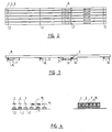
- the conveyor floor comprises in the embodiment according to fig. 1 longitudinally extending parallel beams of which the beams 1 consti tute one group, the beams 2 a second group and the beams 3 a third group.
- the embodiment shows three sets of each time a beam 1, 2 and 3 or three beams in group 1, three beams in group 2 and three beams in group 3.
- the numbers may be different, and each group may also comprise a single wide beam.
- each group i.e. the group of beams 1 and so on
- one drive is associated.
- This comprises in the embodiment shown a piston-cylinder device 4, one end of which is connected to a fixed point 5 of one of the beams and through cross-connections to all beams of the group, whereas the other end is connected to a stationary support structure, e.g. comprising cross-beams 6 supported by the floor 8 below the conveyor floor, e.g. a concrete foundation.
- This last mentioned floor may be the floor of a building or the floor of a truck.
- each beam, so each of the beams 1, 2, 3, is supported on the crossbeam 6 by means of a plurality of rolls 7.
- the operation is as follows: when a group of beams, e.g. the beams 3, are moved in forward direction by the associated piston-cylinder device 4, a load (not shown) placed on the floor, remains in rest. The same applies if the drive of the beams 2 is thereafter actuated and also thereafter the drive of the beams 1. For the force imparted by a single group of beams through the friction on the load is not sufficient for moving the load.
- the stroke of the drive cylinders may be e.g. 15 cm, then the distance whereby the rolls move along the cross beams 6 is one half thereof, i.e. 7.5 cm. Also a stroke of 20 cm and more is possible. This applies to rolls which are freely supported, i.,e. move on the support structure and below the conveyor floor beams. If stationary rolls would be provided in a support member on the building floor, only the conveyor floor moves.
- cross beams 6 are provided at the position of the rolls 7 with end flanges 9 so that the rolls remain enclosed by support member.
- the beams are provided, in addition to the support rolls 7, with side rolls 10, which are rotatable around vertical shafts (see fig. 4).
- side rolls 10 which are rotatable around vertical shafts (see fig. 4).
- the beams are warped or warp said rolls may enter into engagement with the beams which therefore are provided with side flanges 8 along which the roll 10 may roll. Thereby the friction is further reduced.
- the beams are shown to the left in fig. 4 as being I-sections, to the right in fig. 4 as being solid concrete beams. In that case the rolls 10 are rotatably received in the side wall of said beams.
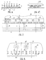
- Fig. 5 shows the above mentioned embodiment in which a carrier member for the rolls 7, here indicated by 12, has a hollow shape extending in the direction of movement of the beams.
- the lower side of the beam 1, 2 or 3 may have a reversed hollow shape at the position of the roll support, whereas then the support structure below the roll extends in a straight line.
- the purpose is in both cases to permit the beam during its movement to lower somewhat, so that its upper side releases the load.
- all beams are lowered simultaneously and thereby also the load, so that in that case the contact with the load is not lost.
- Fig. 6 and 6A show another embodiment in which the rolls for each group are rolls 13, extending along the full width of the floor.
- actuatable lifting devices 14 are provided which are only schematically shown in fig. 6.
- Said lifting devices may also be provided per group of beams instead of per beam.
- the lifting devices may be pneumatic or hydraulic piston cylinder devices, push rods or also air hoses.
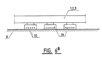
- Fig. 6B shows an embodiment in which the rolls with lifting devices are substituted by air cushions 31 according to the hovercraft principle.
- the conveyor floor beams 1, 2, 3 are connected to air boxes, e.g. constituted by a skirtlike peripheral wall having an open bottom closed by rubber. Said boxes are connected to air pumps permitting to blow pressurized air into the box, said air slowly escaping below the lower edge and through holes 32 adjacent to said lower edge, whereas the box together with the beams is elevated just free from the support structure by the air pressure. Thereafter the concerning group of beams may be shifted simultaneously practically without friction in the longitudinal direction.
- the rolls such as the rolls 7, may comprise, apart from a couple of rolls, groups of rolls combined into a so-called roller vehicle, the rolls of which may constitute railway vehicle wheels.
- the friction due to the rolling movement for shifting the floor will be only about 1 - 5% of the vertical floor loading.
- the friction resistance against moving the load along the beam or group of beams during mutual shifting of the beams becomes practically zero dur to the release from the load.
- a conveyor floor according to the invention may also advantageously be used as a conveyor means for waste when aerobically converting organic waste to compost.
- Fig. 7 shows this application, in which some beams of, in this case, concrete beams 1, 2, 3 are hollow, said hollow beams being equally spaced along the beams and are connected per group to a main conduit 16, provided below the floor 6, by means of flexible houses.
- a main conduit 16 provided below the floor 6, by means of flexible houses.
- air may be blown into the beams through pumps (not shown), said air leaving the beams through apertures 17 provided in the upper wall.
- Organic waste 18, to be converted to compost is supported by the floor.
- the floor is provided in a completely closed building and the air leaving the material 18 is sucked off through filters (not shown) into the atmosphere. Thereby the spreading of stench is avoided.
- FIG. 8 shows schematically another possibility in which air channels 19 have been provided on certain of the floor beams, said channels being likewise connected to the branch-off hoses 15 at their lower ends, said hoses being connected to the main conduit 16.
- the air channels 19 have a restricted nozzle at their upper sides, over which a cap 21 is provided such that the exit apertures are directed laterally while the cap prevents blocking of the nozzle by the waste.
- the arrows 22 indicate the exit and the arrows 22a the inflow of the air from and into the waste mass 18.
- the height of the roof of the building over the beams may be about 2.5 m. This space may be filled almost completely with waste material. Thereby there is only a small unused air space, i.e. a volume of the building in which no waste is present.
- the supply and delivery of the material may take place at the same end of the building, which facilitates the transport.
- the floor portion 25 according to fig. 10 conveys to the right, the floor portion 26 to the left. Between said portions there is provided a conveyor belt 27.
- a conveyor belt 28 which is moved to and fro provides for spreading the material supplied by the belt 27 over the second floor portion 26. Thereby and by the transport by the conveyor belts the material is stirred and thereby aerated.
- Fig. 11 shows a floor having adjacent obliquelike portions 29 and 30 whereby the material drops from the end of portion 29 onto the initial part of portion 30 and is aerated thereby. Due to the small friction resistance to movement of the floor according to the invention, large floor loads, large cantilevered spans and large floor dimensions are permitted.
- the joints between the floor beams should be completely sealed since otherwise so called false air is sucked through the joints, which air then does not pass the heap of waste material.
- the floor beams 1, 2, 3 are e.g. steel corrugated wall sections, the upwardly directed hollow spaces of which are filled with wood cuttings, lava pellets or a similar porous material, in which a perforated conduit 15a is received and connected to a supply or discharge conduit 15. Seals 23 are provided between side flanges of the beams.
Landscapes
- Engineering & Computer Science (AREA)
- Mechanical Engineering (AREA)
- Fertilizers (AREA)
- Processing Of Solid Wastes (AREA)
- Fertilizing (AREA)
Applications Claiming Priority (2)
| Application Number | Priority Date | Filing Date | Title |
|---|---|---|---|
| NL8800728A NL8800728A (nl) | 1988-03-23 | 1988-03-23 | Uit onderling verschuifbare, evenwijdige balken bestaande transportvloer, in het bijzonder voor een afvalcomposteringsinstallatie. |
| NL8800728 | 1988-03-23 |
Publications (3)
| Publication Number | Publication Date |
|---|---|
| EP0334460A2 true EP0334460A2 (de) | 1989-09-27 |
| EP0334460A3 EP0334460A3 (en) | 1990-10-10 |
| EP0334460B1 EP0334460B1 (de) | 1994-07-13 |
Family
ID=19851985
Family Applications (1)
| Application Number | Title | Priority Date | Filing Date |
|---|---|---|---|
| EP89200770A Expired - Lifetime EP0334460B1 (de) | 1988-03-23 | 1989-03-23 | Förderboden mit mehreren parallelen Förderbalken für Kompostieranlagen |
Country Status (5)
| Country | Link |
|---|---|
| EP (1) | EP0334460B1 (de) |
| AT (1) | ATE108408T1 (de) |
| DE (1) | DE68916672T2 (de) |
| ES (1) | ES2055781T3 (de) |
| NL (1) | NL8800728A (de) |
Cited By (7)
| Publication number | Priority date | Publication date | Assignee | Title |
|---|---|---|---|---|
| EP0456578A1 (de) * | 1990-05-09 | 1991-11-13 | Gilbert Marceau | Parallele Stangenförderer |
| WO1992000904A1 (de) * | 1990-07-10 | 1992-01-23 | Georg Hirmann | Vorrichtung zum verschieben von lasten und kräften |
| WO1992019517A1 (fr) * | 1991-05-07 | 1992-11-12 | Gilbert Marceau | Appareil transporteur a barres paralleles |
| WO1994026638A1 (en) * | 1993-05-10 | 1994-11-24 | Paques B.V. | Conveyor installation in the form of a moving floor |
| WO2016012334A1 (fr) * | 2014-07-22 | 2016-01-28 | Amb | Systeme de traitement en continu de produits par apport thermique |
| WO2023080779A1 (en) | 2021-11-02 | 2023-05-11 | Valoriworld B.V. | Dynamic active loading and aeration floor for composting organic material in a closed mobile or stationary reactor |
| LU503128B1 (en) * | 2022-12-02 | 2024-06-03 | Wurth Paul Sa | Reciprocating Floor |
Family Cites Families (6)
| Publication number | Priority date | Publication date | Assignee | Title |
|---|---|---|---|---|
| FR2092724A1 (de) * | 1970-06-12 | 1972-01-28 | Forder Ag | |
| DE2150647A1 (de) * | 1970-10-12 | 1972-04-13 | Ingersoll Rand Co | Vorrichtung zum Foerdern von Werkstuecken |
| US4071137A (en) * | 1976-12-13 | 1978-01-31 | Auburn Foundry, Inc. | Walking beam conveyor apparatus and method of operating the same |
| US4474285A (en) * | 1982-02-08 | 1984-10-02 | Foster Raymond K | Drive unit mount for reciprocating floor conveyor |
| DE3277965D1 (en) * | 1982-04-30 | 1988-02-18 | Koyo Chuki Co | A foundry pouring station table |
| US4798802A (en) * | 1987-07-28 | 1989-01-17 | Ryan Richard M | Method for accelerating composting of organic matter and composting reactor therefor |
-
1988
- 1988-03-23 NL NL8800728A patent/NL8800728A/nl not_active Application Discontinuation
-
1989
- 1989-03-23 DE DE68916672T patent/DE68916672T2/de not_active Expired - Fee Related
- 1989-03-23 ES ES89200770T patent/ES2055781T3/es not_active Expired - Lifetime
- 1989-03-23 AT AT89200770T patent/ATE108408T1/de not_active IP Right Cessation
- 1989-03-23 EP EP89200770A patent/EP0334460B1/de not_active Expired - Lifetime
Cited By (14)
| Publication number | Priority date | Publication date | Assignee | Title |
|---|---|---|---|---|
| EP0456578A1 (de) * | 1990-05-09 | 1991-11-13 | Gilbert Marceau | Parallele Stangenförderer |
| FR2661899A1 (fr) * | 1990-05-09 | 1991-11-15 | Marceau Gilbert | Transporteur a barres paralleles. |
| WO1992000904A1 (de) * | 1990-07-10 | 1992-01-23 | Georg Hirmann | Vorrichtung zum verschieben von lasten und kräften |
| WO1992019517A1 (fr) * | 1991-05-07 | 1992-11-12 | Gilbert Marceau | Appareil transporteur a barres paralleles |
| WO1994026638A1 (en) * | 1993-05-10 | 1994-11-24 | Paques B.V. | Conveyor installation in the form of a moving floor |
| NL9300800A (nl) * | 1993-05-10 | 1994-12-01 | Pacques Bv | Transportinrichting in de vorm van een bewegende vloer. |
| WO2016012334A1 (fr) * | 2014-07-22 | 2016-01-28 | Amb | Systeme de traitement en continu de produits par apport thermique |
| JP2017526497A (ja) * | 2014-07-22 | 2017-09-14 | アエムベ | 熱入力による生成物の連続処理のためのシステム |
| US9943892B2 (en) | 2014-07-22 | 2018-04-17 | Amb | System for the continuous treatment of products by thermal input |
| AU2015294082B2 (en) * | 2014-07-22 | 2018-10-11 | Amb | System for the continuous treatment of products by thermal input |
| RU2690525C2 (ru) * | 2014-07-22 | 2019-06-04 | Амб | Система непрерывной термической обработки веществ |
| WO2023080779A1 (en) | 2021-11-02 | 2023-05-11 | Valoriworld B.V. | Dynamic active loading and aeration floor for composting organic material in a closed mobile or stationary reactor |
| LU503128B1 (en) * | 2022-12-02 | 2024-06-03 | Wurth Paul Sa | Reciprocating Floor |
| WO2024115463A1 (en) * | 2022-12-02 | 2024-06-06 | Paul Wurth S.A. | Reciprocating floor |
Also Published As
| Publication number | Publication date |
|---|---|
| NL8800728A (nl) | 1989-10-16 |
| EP0334460B1 (de) | 1994-07-13 |
| ES2055781T3 (es) | 1994-09-01 |
| DE68916672T2 (de) | 1994-11-03 |
| ATE108408T1 (de) | 1994-07-15 |
| DE68916672D1 (de) | 1994-08-18 |
| EP0334460A3 (en) | 1990-10-10 |
Similar Documents
| Publication | Publication Date | Title |
|---|---|---|
| US5088873A (en) | Manipulator mixed freight handling system | |
| US4434691A (en) | Method and apparatus for sealing cut sheet material | |
| CN112830182B (zh) | 一种编织袋竖直码垛装置 | |
| EP0457938A1 (de) | System zum Handhaben von gemischter Fracht | |
| US5067867A (en) | Conveyor for mixed freight handling system | |
| EP0334460A2 (de) | Förderboden mit mehreren parallelen Förderbalken für Kompostieranlagen | |
| EP0524375A1 (de) | Durchlauf-Gärschrank | |
| CN101804901A (zh) | 升降梁输送器 | |
| EP0595613A1 (de) | Vertikalförderer | |
| EP0271116B1 (de) | Schneidtisch mit Vakuum-Ansaugung | |
| CN1257819A (zh) | 充气包装衬垫的输送系统 | |
| US4440253A (en) | Crawler-type transport apparatus | |
| EP0307039B1 (de) | Rollerbahn | |
| US20030157702A1 (en) | Composting system | |
| JP3015351B1 (ja) | 重量物搬送装置 | |
| CN214398962U (zh) | 一种商标纸捆智能码垛系统 | |
| SU1740673A1 (ru) | Устройство дл селективной выемки полезного ископаемого | |
| CN217457990U (zh) | 一种高效的预制件生产线上料系统 | |
| CN221025901U (zh) | 一种用于钢筋网作业面的物料搬运装置 | |
| CN221253839U (zh) | 一种适用于堆石坝的面板施工物料运输装置 | |
| CN223575532U (zh) | 高空拆垛码垛清洗系统 | |
| JPH023443Y2 (de) | ||
| JP2827107B2 (ja) | 鋼材の搬送装置 | |
| JP2576381Y2 (ja) | 積荷移動装置 | |
| CN210972606U (zh) | 一种可分类的建材用输送带 |
Legal Events
| Date | Code | Title | Description |
|---|---|---|---|
| PUAI | Public reference made under article 153(3) epc to a published international application that has entered the european phase |
Free format text: ORIGINAL CODE: 0009012 |
|
| AK | Designated contracting states |
Kind code of ref document: A2 Designated state(s): AT BE CH DE ES FR GB GR IT LI LU NL SE |
|
| PUAL | Search report despatched |
Free format text: ORIGINAL CODE: 0009013 |
|
| AK | Designated contracting states |
Kind code of ref document: A3 Designated state(s): AT BE CH DE ES FR GB GR IT LI LU NL SE |
|
| 17P | Request for examination filed |
Effective date: 19910410 |
|
| 17Q | First examination report despatched |
Effective date: 19930118 |
|
| RIN1 | Information on inventor provided before grant (corrected) |
Inventor name: RUTTE-HOEKSTRA, JETSKE |
|
| GRAA | (expected) grant |
Free format text: ORIGINAL CODE: 0009210 |
|
| RAP1 | Party data changed (applicant data changed or rights of an application transferred) |
Owner name: J.B. RUTTE B.V. |
|
| AK | Designated contracting states |
Kind code of ref document: B1 Designated state(s): AT BE CH DE ES FR GB GR IT LI LU NL SE |
|
| PG25 | Lapsed in a contracting state [announced via postgrant information from national office to epo] |
Ref country code: LI Effective date: 19940713 Ref country code: GR Free format text: LAPSE BECAUSE OF FAILURE TO SUBMIT A TRANSLATION OF THE DESCRIPTION OR TO PAY THE FEE WITHIN THE PRESCRIBED TIME-LIMIT Effective date: 19940713 Ref country code: CH Effective date: 19940713 |
|
| REF | Corresponds to: |
Ref document number: 108408 Country of ref document: AT Date of ref document: 19940715 Kind code of ref document: T |
|
| REF | Corresponds to: |
Ref document number: 68916672 Country of ref document: DE Date of ref document: 19940818 |
|
| REG | Reference to a national code |
Ref country code: ES Ref legal event code: FG2A Ref document number: 2055781 Country of ref document: ES Kind code of ref document: T3 |
|
| ITF | It: translation for a ep patent filed | ||
| REG | Reference to a national code |
Ref country code: CH Ref legal event code: PL |
|
| ET | Fr: translation filed | ||
| EAL | Se: european patent in force in sweden |
Ref document number: 89200770.9 |
|
| PG25 | Lapsed in a contracting state [announced via postgrant information from national office to epo] |
Ref country code: LU Free format text: LAPSE BECAUSE OF NON-PAYMENT OF DUE FEES Effective date: 19950331 |
|
| PLBE | No opposition filed within time limit |
Free format text: ORIGINAL CODE: 0009261 |
|
| STAA | Information on the status of an ep patent application or granted ep patent |
Free format text: STATUS: NO OPPOSITION FILED WITHIN TIME LIMIT |
|
| 26N | No opposition filed | ||
| PGFP | Annual fee paid to national office [announced via postgrant information from national office to epo] |
Ref country code: AT Payment date: 19960125 Year of fee payment: 8 |
|
| PGFP | Annual fee paid to national office [announced via postgrant information from national office to epo] |
Ref country code: ES Payment date: 19960329 Year of fee payment: 8 |
|
| PG25 | Lapsed in a contracting state [announced via postgrant information from national office to epo] |
Ref country code: AT Effective date: 19970323 |
|
| PG25 | Lapsed in a contracting state [announced via postgrant information from national office to epo] |
Ref country code: ES Free format text: LAPSE BECAUSE OF NON-PAYMENT OF DUE FEES Effective date: 19970324 |
|
| REG | Reference to a national code |
Ref country code: ES Ref legal event code: FD2A Effective date: 19990503 |
|
| REG | Reference to a national code |
Ref country code: FR Ref legal event code: ST |
|
| REG | Reference to a national code |
Ref country code: FR Ref legal event code: RN |
|
| REG | Reference to a national code |
Ref country code: FR Ref legal event code: IC |
|
| PGFP | Annual fee paid to national office [announced via postgrant information from national office to epo] |
Ref country code: GB Payment date: 20010322 Year of fee payment: 13 Ref country code: FR Payment date: 20010322 Year of fee payment: 13 |
|
| PGFP | Annual fee paid to national office [announced via postgrant information from national office to epo] |
Ref country code: SE Payment date: 20010323 Year of fee payment: 13 Ref country code: DE Payment date: 20010323 Year of fee payment: 13 Ref country code: BE Payment date: 20010323 Year of fee payment: 13 |
|
| PGFP | Annual fee paid to national office [announced via postgrant information from national office to epo] |
Ref country code: NL Payment date: 20010330 Year of fee payment: 13 |
|
| REG | Reference to a national code |
Ref country code: FR Ref legal event code: RU |
|
| REG | Reference to a national code |
Ref country code: GB Ref legal event code: IF02 |
|
| PG25 | Lapsed in a contracting state [announced via postgrant information from national office to epo] |
Ref country code: GB Free format text: LAPSE BECAUSE OF NON-PAYMENT OF DUE FEES Effective date: 20020323 |
|
| PG25 | Lapsed in a contracting state [announced via postgrant information from national office to epo] |
Ref country code: SE Free format text: LAPSE BECAUSE OF NON-PAYMENT OF DUE FEES Effective date: 20020324 |
|
| PG25 | Lapsed in a contracting state [announced via postgrant information from national office to epo] |
Ref country code: BE Free format text: LAPSE BECAUSE OF NON-PAYMENT OF DUE FEES Effective date: 20020331 |
|
| BERE | Be: lapsed |
Owner name: J.B. *RUTTE B.V. Effective date: 20020331 |
|
| PG25 | Lapsed in a contracting state [announced via postgrant information from national office to epo] |
Ref country code: NL Free format text: LAPSE BECAUSE OF NON-PAYMENT OF DUE FEES Effective date: 20021001 Ref country code: DE Free format text: LAPSE BECAUSE OF NON-PAYMENT OF DUE FEES Effective date: 20021001 |
|
| EUG | Se: european patent has lapsed |
Ref document number: 89200770.9 |
|
| GBPC | Gb: european patent ceased through non-payment of renewal fee |
Effective date: 20020323 |
|
| PG25 | Lapsed in a contracting state [announced via postgrant information from national office to epo] |
Ref country code: FR Free format text: LAPSE BECAUSE OF NON-PAYMENT OF DUE FEES Effective date: 20021129 |
|
| NLV4 | Nl: lapsed or anulled due to non-payment of the annual fee |
Effective date: 20021001 |
|
| REG | Reference to a national code |
Ref country code: FR Ref legal event code: ST |
|
| PG25 | Lapsed in a contracting state [announced via postgrant information from national office to epo] |
Ref country code: IT Free format text: LAPSE BECAUSE OF NON-PAYMENT OF DUE FEES;WARNING: LAPSES OF ITALIAN PATENTS WITH EFFECTIVE DATE BEFORE 2007 MAY HAVE OCCURRED AT ANY TIME BEFORE 2007. THE CORRECT EFFECTIVE DATE MAY BE DIFFERENT FROM THE ONE RECORDED. Effective date: 20050323 |