EP0334272B1 - Hydraulische Ventilöffnungseinheit im Zylinderkopf einer Brennkraftmaschine - Google Patents
Hydraulische Ventilöffnungseinheit im Zylinderkopf einer Brennkraftmaschine Download PDFInfo
- Publication number
- EP0334272B1 EP0334272B1 EP89104989A EP89104989A EP0334272B1 EP 0334272 B1 EP0334272 B1 EP 0334272B1 EP 89104989 A EP89104989 A EP 89104989A EP 89104989 A EP89104989 A EP 89104989A EP 0334272 B1 EP0334272 B1 EP 0334272B1
- Authority
- EP
- European Patent Office
- Prior art keywords
- valve
- opening unit
- piston
- hydraulic
- stroke
- Prior art date
- Legal status (The legal status is an assumption and is not a legal conclusion. Google has not performed a legal analysis and makes no representation as to the accuracy of the status listed.)
- Expired - Lifetime
Links
Images

Classifications
-
- F—MECHANICAL ENGINEERING; LIGHTING; HEATING; WEAPONS; BLASTING
- F01—MACHINES OR ENGINES IN GENERAL; ENGINE PLANTS IN GENERAL; STEAM ENGINES
- F01L—CYCLICALLY OPERATING VALVES FOR MACHINES OR ENGINES
- F01L9/00—Valve-gear or valve arrangements actuated non-mechanically
- F01L9/10—Valve-gear or valve arrangements actuated non-mechanically by fluid means, e.g. hydraulic
- F01L9/11—Valve-gear or valve arrangements actuated non-mechanically by fluid means, e.g. hydraulic in which the action of a cam is being transmitted to a valve by a liquid column
- F01L9/12—Valve-gear or valve arrangements actuated non-mechanically by fluid means, e.g. hydraulic in which the action of a cam is being transmitted to a valve by a liquid column with a liquid chamber between a piston actuated by a cam and a piston acting on a valve stem
- F01L9/14—Valve-gear or valve arrangements actuated non-mechanically by fluid means, e.g. hydraulic in which the action of a cam is being transmitted to a valve by a liquid column with a liquid chamber between a piston actuated by a cam and a piston acting on a valve stem the volume of the chamber being variable, e.g. for varying the lift or the timing of a valve
-
- F—MECHANICAL ENGINEERING; LIGHTING; HEATING; WEAPONS; BLASTING
- F01—MACHINES OR ENGINES IN GENERAL; ENGINE PLANTS IN GENERAL; STEAM ENGINES
- F01L—CYCLICALLY OPERATING VALVES FOR MACHINES OR ENGINES
- F01L1/00—Valve-gear or valve arrangements, e.g. lift-valve gear
- F01L1/02—Valve drive
- F01L1/04—Valve drive by means of cams, camshafts, cam discs, eccentrics or the like
- F01L1/08—Shape of cams
-
- F—MECHANICAL ENGINEERING; LIGHTING; HEATING; WEAPONS; BLASTING
- F01—MACHINES OR ENGINES IN GENERAL; ENGINE PLANTS IN GENERAL; STEAM ENGINES
- F01L—CYCLICALLY OPERATING VALVES FOR MACHINES OR ENGINES
- F01L1/00—Valve-gear or valve arrangements, e.g. lift-valve gear
- F01L1/34—Valve-gear or valve arrangements, e.g. lift-valve gear characterised by the provision of means for changing the timing of the valves without changing the duration of opening and without affecting the magnitude of the valve lift
- F01L1/344—Valve-gear or valve arrangements, e.g. lift-valve gear characterised by the provision of means for changing the timing of the valves without changing the duration of opening and without affecting the magnitude of the valve lift changing the angular relationship between crankshaft and camshaft, e.g. using helicoidal gear
- F01L1/3442—Valve-gear or valve arrangements, e.g. lift-valve gear characterised by the provision of means for changing the timing of the valves without changing the duration of opening and without affecting the magnitude of the valve lift changing the angular relationship between crankshaft and camshaft, e.g. using helicoidal gear using hydraulic chambers with variable volume to transmit the rotating force
- F01L2001/34423—Details relating to the hydraulic feeding circuit
- F01L2001/34446—Fluid accumulators for the feeding circuit
Definitions
- the invention relates to a hydraulic valve opening unit of the type specified in the preamble of the first claim and is based on the generic DE-OS 36 21 402.
- Hydraulic valve opening units are known in various designs.
- a cam actuates a master piston, which acts on a working piston via a hydraulic chamber, the latter resting on the stem of a lift valve.
- the master piston and the working piston are usually arranged coaxially with one another.
- this arrangement requires a large amount of space and is very tall.
- the disadvantages with regard to the hydraulic transmission behavior are evident. Therefore, in the above scripture of the master piston arranged at right angles to the working piston or to the stroke valve actuated by it.
- the master piston is arranged spatially between the inlet and outlet valve and its axis not only angled, but also offset from the axis of the inlet valve. This makes it possible to supply the hydraulic fluid acting on the working piston to it from the side, that is to say tangentially.
- the cross section of the master piston is larger than the cross section of the working piston, there is a hydraulic ratio. High valve or working piston strokes can be achieved with significantly lower strokes of the master piston. The space requirement is thus reduced in the axial direction of the master piston; the cross-sectional area of the cam that determines the maximum master piston stroke can also be kept smaller.
- braking devices are often provided which influence the speed of the valve closing movement caused by the removal of hydraulic fluid.
- the hydraulic fluid discharged usually flows through a throttle gap.
- braking device concentrically with the working piston and in particular within it.
- Claim 4 advantageously develops the cam actuating the master piston.
- the cam can be designed such that the closing movement of the valve is always brought about in all operating points of the internal combustion engine by the removal of hydraulic fluid. This reduces the mechanical load on the master piston and allows it to be simplified or made correspondingly small. The mechanical load on the cam and master piston therefore only has to be taken into account in the initial phase of the valve opening movement. If a hydraulic transmission ratio is integrated in the hydraulic valve opening unit according to the invention, a rapid valve opening movement which is desired with regard to the dynamics of charge change can be achieved even with relatively little acceleration of the master piston, which means low mechanical loads and thus small size.
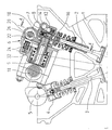
- An intake valve 2 is arranged in a cylinder head 1 of an internal combustion engine, and an exhaust valve 3 is arranged at an angle thereto. While the latter is actuated by a cam 5, as is generally the case with the interposition of a hydraulic lash adjuster 4, a hydraulic valve opening unit, designated as a whole by 6, is provided for the inlet valve 2.
- This consists essentially of a housing 7, a piston 8 actuating the inlet valve 2, one with this in hydraulic Ver binding master piston 9, and a cam acting on the master piston 9. 10
- the axis of the master piston 9 is angled and offset from the axis of the working piston 8 or the inlet valve 2.
- the master piston 9 is arranged within the V-space spanned by the inlet valve 2 and the outlet valve 3, an extremely space-saving arrangement is created. This can also be seen from FIG. 2, two valve opening units according to the invention being shown here in mirror image next to one another.
- the hydraulic valve opening unit 6 operates as follows: Hydraulic fluid enters a hydraulic chamber 16 via an inlet channel 14 and a check valve 12.
- the hydraulic chamber 16 also has a control channel 18 which opens into a storage space 20 and can be closed by means of a slide 22.
- This slide 22 is actuated by an eccentric shaft 26 acting against a tappet 24.
- the hydraulic chamber 16 is further delimited by the master piston 9, the effective cross section of which is larger than the effective cross section of the working piston 8. If the master piston 9 is now moved by rotation of the cam 10, it displaces hydraulic fluid from the hydraulic chamber 16 via a valve with a check valve 27 provided channel 28 in a pressure chamber 30 (see in particular. Fig. 2). As a result, the working piston 8 is moved and thus causes the opening valve 2 to open. This process is ended when either the stroke of the master piston 9 becomes smaller or the control channel 18 is released. For this purpose, the slide 22 can be moved in or against the direction of arrow 32 by rotation of the eccentric shaft 26.
- throttle gap 34 is determined by one within the Working piston 8 provided, designated in its entirety with 36 braking device (see in particular. Fig. 2).
- that braking device 36 consists of a tapered longitudinal groove 37 provided in the outer surface of the working piston 8 and the non-return valve 28 already explained thus narrowing in the course of the valve closing movement, formed together with a projection 35 of the housing 7, throttle gap 34.
- Fig. 3 shows an exemplary elevation curve of the master piston depending on the cam angle ⁇ . That curve is divided into three main phases. In the first phase designated I, a maximum elevation ⁇ h per cam angle change ⁇ is aimed for. That maximum valve lift increase is determined in particular by the mechanical strength of the cam 10 and the master piston 9. Since, according to the invention, a hydraulic transmission ratio is built into the hydraulic valve opening unit 6, the cross-section of the master piston 9 is therefore larger than the cross-section of the working piston 8, is sufficient to achieve one desired rapid valve opening movement a relatively slower stroke course of the master piston 9. Thus, the master piston 9 can be made light and in particular compact.
- phase II following that first phase represents a transition area to phase III, which in turn has a decreasing master piston stroke h.
- Phase II also covers a relatively wide cam angle range ⁇ p * , since that phase represents the usual working range for intake valve 2.
- the valve closing movement is initiated in the entire operating range of the internal combustion engine by actuating the slide 22 and discharging hydraulic fluid into the storage space 20.
- This has the advantage that the stroke of the master piston 9 can be designed in phase III taking mechanical aspects into account. With this cam contour, an optimal filling process of the pressure chamber 30 can be achieved in interaction with the design of the working piston 8 and the check valve 27.
Description
- Die Erfindung betrifft eine hydraulische Ventilöffnungseinheit der im Oberbegriff des ersten Anspruchs angegebenen Art und geht aus von der gattungsbildenden DE-OS 36 21 402.
- Hydraulische Ventilöffnungseinheiten sind in mannigfachen Ausführungen bekannt. Dabei betätigt ein Nocken einen Geberkolben, welcher über einen Hydraulikraum auf einen Arbeitskolben einwirkt, wobei letzterer auf dem Schaft eines Hubventiles aufliegt. Zumeist sind dabei der Geberkolben und der Arbeitskolben gleichachsig zueinander angeordnet. Diese Anordnung erfordert jedoch einen hohen Raumbedarf und baut dabei sehr hoch. Vorgeschlagen wurde bereits auch, Geberkolben und Arbeitskolben parallel nebeneinander anzuordnen. Hierdurch ergeben sich jedoch große Mengen von bewegter Hydraulikflüssigkeit. Die Nachteile hinsichtlich des hydraulischen Übertragungsverhaltens sind evident. Deshalb ist in der o.g. Schrift der Geberkolben rechtwinkelig zum Arbeitskolben bzw. zu dem von diesem betätigten Hubventil angeordnet.
- Wenngleich jene Anordnung hinsichtlich des erforderlichen Bauraumes eine Verbesserung darstellt, erfordert diese immer noch unverhältnismäßig großvolumig bauende Zylinderköpfe. Es ist daher Aufgabe der Erfindung, eine hydraulische Ventilöffnungseinheit der im Oberbegriff des ersten Anspruchs angegebenen Art hinsichtlich des erforderlichen Bauraumes weiter zu optimieren.
- Diese Aufgabe wird durch die kennzeichnenden Merkmale des ersten Anspruchs gelöst.
- Bei winkeliger Anordnung von Einlaßventil und Auslaßventil, welche ihrerseits Vorteile hinsichtlich der möglichen Brennraumgestaltung sowie der Ausbildung der Einlaß- und Auslaßkanäle bietet, ist eine besonders kompakt bauende Anordnung erzielbar, wenn zum einen der Geberkolben räumlich zwischen Einlaß- und Auslaßventil angeordnet ist und dabei dessen Achse nicht nur winkelig, sondern darüber hinaus versetzt zur Achse des Einlaßventiles verläuft. Hiermit ist es nämlich möglich, die auf den Arbeitskolben einwirkende Hydraulikflüssigkeit diesem quasi von der Seite her, also tangential zuzuführen.
- Vorteilhafte Aus- und Weiterbildungen beschreiben die Unteransprüche.
- Ist der Querschnitt des Geberkolbens größer als der Querschnitt des Arbeitskolbens, so liegt eine hydraulische Übersetzung vor. Hohe Ventil- bzw. Arbeitskolbenhübe sind mit deutlich geringeren Hüben des Geberkolbens erzielbar. In Achsrichtung des Geberkolbens wird der Raumbedarf somit verringert; auch die den maximalen Geberkolbenhub bestimmende Querschnittsfläche des Nockens kann kleiner gehalten werden.
- In hydraulischen Ventilöffnungseinheiten sind des öfteren Bremsvorrichtungen vorgesehen, welche die durch eine Abfuhr von Hydraulikflüssigkeit hervorgerufene Ventilschließbewegung geschwindigkeitsmäßig beeinflussen. Dazu strömt die abgeführte Hydraulikmenge zumeist über einen Drosselspalt. Erfindungsgemäß wird nunmehr vorgeschlagen, jene Bremsvorrichtung konzentrisch zum Arbeitskolben und insbesondere innerhalb diesem anzuordnen. Alternativ ist es auch möglich, den Arbeitskolben innerhalb der entsprechend ausgebildeten Bremsvorrichtung vorzusehen. Beide Varianten reduzieren den erforderlichen Bauraum um ein weiteres.
- Anspruch 4 bildet den den Geberkolben betätigenden Nocken vorteilhaft weiter. Insbesondere bei Verwendung einer drosselnden Bremsvorrichtung kann der Nocken derart ausgebildet sein, daß die Schließbewegung des Ventiles in allen Betriebspunkten der Brennkraftmaschine stets durch Abfuhr von Hydraulikflüssigkeit hervorgerufen wird. Dies reduziert die mechanische Belastung des Geberkolbens und erlaubt, diesen vereinfacht bzw. entsprechend kleinbauend auszuführen. Die mechanische Belastung von Nocken und Geberkolben muß somit lediglich in der Anfangsphase der Ventilöffnungsbewegung berücksichtigt werden. Ist dabei in der erfindungsgemäßen hydraulischen Ventilöffnungseinheit ein hydraulisches Übersetzungsverhältnis integriert, so kann auch bei relativ geringer Beschleunigung des Geberkolbens-dies bedeutet geringe mechanische Belastungen und somit geringe Baugröße-eine im Hinblick auf die Ladungswechseldynamik erwünschte schnelle Ventilöffnungsbewegung erzielt werden.
- Im folgenden wird die Erfindung anhand eines bevorzugten Ausführungsbeispiels näher beschrieben. Es zeigt :
- Fig. 1 einen Querschnitt durch einen Zylinderkopf einer Brennkraftmaschine mit einer hydraulischen Ventilöffnungseinheit,
- Fig. 2 den Schnitt A-A aus Fig. 1, sowie
- Fig. 3 einen beispielhaften durch die Nockenform gegebenen Hubverlauf des Geberkolbens.
- In einem Zylinderkopf 1 einer Brennkraftmaschine ist ein Einlaßventil 2, sowie winkelig zu diesem ein Auslaßventil 3 angeordnet. Während letzteres wie allgemein üblich unter Zwischenschaltung eines hydraulischen Spielausgleichselementes 4 von einem Nocken 5 betätigt wird, ist für das Einlaßventil 2 eine ihrer Gesamtheit mit 6 bezeichnete hydraulische Ventilöffnungseinheit vorgesehen. Diese besteht im wesentlichen aus einem Gehäuse 7, einem das Einlaßventil 2 betätigenden Arbeitskolben 8, einem mit diesem in hydraulischer Verbindung stehenden Geberkolben 9, sowie einem auf den Geberkolben 9 einwirkenden Nocken 10.
- Erfindungsgemäß liegt die Achse des Geberkolbens 9 winkelig und versetzt zur Achse des Arbeitskolbens 8 bzw. des Einlaßventiles 2. Indem zusätzlich der Geberkolben 9 innerhalb des von dem Einlaßventil 2 sowie dem Auslaßventil 3 aufgespannten V-Raumes angeordnet ist, ist eine äußerst raumsparende Anordnung geschaffen. Ersichtlich wird dies auch aus Fig. 2, wobei hier zwei erfindungsgemäße Ventilöffnungseinheiten spiegelbildlich nebeneinander gezeigt sind.
- Die Wirkungsweise der hydraulischen Ventilöffnungseinheit 6 ist dabei wie folgt : Über einen Zulaufkanal 14 sowie ein Rückschlagventil 12 gelangt Hydraulikflüssigkeit in eine Hydraulikkammer 16. Diese weist zudem einen Absteuerkanal 18 auf, welcher in einen Speicherraum 20 mündet und mittels eines Schiebers 22 verschließbar ist. Betätigt wird dieser Schieber 22 von einer gegen einen Stößel 24 wirkenden Exzenterwelle 26.
- Begrenzt wird die Hydraulikkammer 16 desweiteren vom Geberkolben 9, wobei dessen wirksamer Querschnitt größer ist als der wirksame Querschnitt des Arbeitskolbens 8. Wird nun durch Rotation des Nockens 10 der Geberkolben 9 bewegt, so verdrängt er Hydraulikflüssigkeit aus der Hydraulikkammer 16 über einen mit einem Rückschlagventil 27 versehenen Kanal 28 in eine Druckkammer 30 (siehe insbes. Fig. 2). Hierdurch wird derArbeitskolben 8 bewegt und veranlaßt somit eine Öffnungsbewegung des Einlaßventiles 2. Dieser Vorgang wird beendet, wenn entweder der Hub des Geberkolbens 9 geringer wird oder der Absteuerkanai 18 freigegeben wird. Dazu kann durch Rotation der Exzenterwelle 26 der Schieber 22 in bzw. gegen Pfeilrichtung 32 bewegt werden. Gibt der Schieber 22 den Absteuerkanal 18 frei, so gelangt die Hydraulikflüssigkeit aus der Druckkammer 30 über einen sich im Verlauf der Schließbewegung des Einlaßventiles 2 verengenden Drosselspalt 34 in die Hydraulikkammer 16 und schließlich in den Speicherraum 20. Bestimmt wird der Drosselspalt 34 von einer innerhalb des Arbeitskolbens 8 vorgesehenen, in ihrer Gesamtheit mit 36 bezeichneten Bremsvorrichtung (siehe insbes. Fig. 2). Im wesentlichen besteht jene Bremsvorrichtung 36 aus einer in der Mantelfläche des Arbeitskolbens 8 vorgesehenen, sich verjüngenden Längsnut 37 sowie dem bereits erläuterten Rückschlagventil 28. Da letzteres eine Abfuhr von Hydraulikmedium aus der Druckkammer 30 verhindert, strömt das Medium über die sich verjüngende Längsnut 37 und den somit sich im Laufe der Ventilschließbewegung verengenden, zusammen mit einem Vorsprung 35 des Gehäuses 7 gebildeten Drosselspalt 34.
- Fig. 3 zeigt eine beispielhafte Erhebungskurve des Geberkolbens in Abhängigkeit vom Nockenwinkel ϕ. Jene Erhebungskurve ist in drei wesentliche Phasen unterteilt. In der mit I bezeichneten ersten Phase wird eine maximale Erhebung Δh je Nockenwinkeländerung Δϕ angestrebt. Bestimmt wird jene maximale Ventilhubzunahme insbesondere durch die mechanische Festigkeit des Nockens 10 sowie des Geberkolbens 9. Da erfindungsgemäß in der hydraulischen Ventilöffnungseinheit 6 ein hydraulisches Übersetzungsverhältnis eingebaut ist, der Querschnitt des Geberkolbens 9 also größer ist als der Querschnitt des Arbeitskolbens 8, genügt zur Erzielung einer erwünschten schnellen Ventilöffnungsbewegung ein relativ langsamerer Hubverlauf des Geberkolbens 9. Somit kann der Geberkolben 9 leicht und insbesondere kompaktbauend ausgeführt werden.
- Die an jene erste Phase anschließende Phase II stellt einen Übergangsbereich zur Phase III dar, welche ihrerseits einen abnehmenden Geberkolben-Hub h aufweist. Die Phase II überdeckt dabei auch deshalb einen relativ breiten Nockenwinkelbereich <p*, da jene Phase den üblichen Arbeitsbereich für das Einlaßventil 2 darstellt. Erfindungsgemäß wird nämlich im gesamten Betriebsbereich der Brennkraftmaschine die Ventilschließbewegung durch Betätigung des Schiebers 22 sowie Abfuhr von Hydraulikflüssigkeit in den Speicherraum 20 eingeleitet. Dies hat den Vorteil, daß der Hubverlauf des Geberkolbens 9 in der Phase III unter Berücksichtigung mechanischer Gesichtspunkte ausgelegt werden kann. Mit dieser Nockenkontur kann ein optimaler Befüllvorgang der Druckkammer 30 im Zusammenspiel mit der Gestaltung des Arbeitskolbens 8 sowie des Rückschlagventiles 27 erzielt werden. Da an letzterem unter strömungsdynamischen Gesichtspunkten (Schwingungsverhalten sowie Dampfblasenbildung) geringe Strömungsgeschwindigkeiten erwünscht sind, können mit einer derart flachen Nockenkontur der Phase 11 lange Befüllzeiten realisiert werden. Da somit während der Phase II stets eine Absteuerung des Ventilhubes erfolgt, lassen sich zusätzlich enge Toleranzen insbesondere in Zusammenhang mit der Ansteuerung der Exzenterwelle 26 vermeiden, wenn jene Phase einen relativ breiten Nockenwinkelbereich (<p*) überstreicht.
Claims (4)
Applications Claiming Priority (2)
| Application Number | Priority Date | Filing Date | Title |
|---|---|---|---|
| DE3809953 | 1988-03-24 | ||
| DE3809953A DE3809953C1 (de) | 1988-03-24 | 1988-03-24 |
Publications (2)
| Publication Number | Publication Date |
|---|---|
| EP0334272A1 EP0334272A1 (de) | 1989-09-27 |
| EP0334272B1 true EP0334272B1 (de) | 1991-07-24 |
Family
ID=6350591
Family Applications (1)
| Application Number | Title | Priority Date | Filing Date |
|---|---|---|---|
| EP89104989A Expired - Lifetime EP0334272B1 (de) | 1988-03-24 | 1989-03-21 | Hydraulische Ventilöffnungseinheit im Zylinderkopf einer Brennkraftmaschine |
Country Status (3)
| Country | Link |
|---|---|
| EP (1) | EP0334272B1 (de) |
| DE (2) | DE3809953C1 (de) |
| ES (1) | ES2024058B3 (de) |
Families Citing this family (2)
| Publication number | Priority date | Publication date | Assignee | Title |
|---|---|---|---|---|
| US5127375A (en) * | 1991-04-04 | 1992-07-07 | Ford Motor Company | Hydraulic valve control system for internal combustion engines |
| PL1674673T3 (pl) | 2004-12-23 | 2007-08-31 | Fiat Ricerche | Silnik spalinowy z hydraulicznie zmiennymi zaworami |
Family Cites Families (5)
| Publication number | Priority date | Publication date | Assignee | Title |
|---|---|---|---|---|
| CH243908A (de) * | 1944-11-27 | 1946-08-15 | Schweizerische Lokomotiv | Flüssigkeitsbremse mit Rückschlagventil am Passivkolben von hydraulisch gesteuerten Ventilen von Brennkraftmaschinen. |
| DE2840445C2 (de) * | 1978-09-16 | 1984-10-04 | M.A.N. Maschinenfabrik Augsburg-Nürnberg AG, 8500 Nürnberg | Hydraulische Vorrichtung zum Betätigen eines Gaswechselventils für Brennkraftmaschinen |
| DE3611476A1 (de) * | 1986-04-05 | 1987-10-08 | Irm Antriebstech Gmbh | Verfahren zur betaetigung von ventilen zum ladungswechsel bei brennkraftmaschinen mit direkter hydraulischer uebertragung |
| DE3621402A1 (de) * | 1986-06-26 | 1988-01-14 | Kloeckner Humboldt Deutz Ag | Hydraulisch betaetigter stoessel |
| DE3625664A1 (de) * | 1986-07-29 | 1988-02-04 | Bayerische Motoren Werke Ag | Vorrichtung zur beeinflussung des von einem nocken gesteuerten ventilhubes |
-
1988
- 1988-03-24 DE DE3809953A patent/DE3809953C1/de not_active Expired
-
1989
- 1989-03-21 DE DE8989104989T patent/DE58900184D1/de not_active Expired - Lifetime
- 1989-03-21 ES ES89104989T patent/ES2024058B3/es not_active Expired - Lifetime
- 1989-03-21 EP EP89104989A patent/EP0334272B1/de not_active Expired - Lifetime
Also Published As
| Publication number | Publication date |
|---|---|
| DE3809953C1 (de) | 1989-08-24 |
| DE58900184D1 (de) | 1991-08-29 |
| ES2024058B3 (es) | 1992-02-16 |
| EP0334272A1 (de) | 1989-09-27 |
Similar Documents
| Publication | Publication Date | Title |
|---|---|---|
| DE19853355C1 (de) | Hydraulisch steuerbares Hubventil | |
| DE19621719C1 (de) | Hydraulische Ventilsteuervorrichtung | |
| EP0432404A2 (de) | Ventilsteuerung für Gaswechselventile von Brennkraftmaschinen | |
| DE4411857A1 (de) | Hydraulisch betriebene Ventilsteuerungseinrichtung mit hydraulischer Dämpfung | |
| DE4332119A1 (de) | Kraftstoffeinspritzeinrichtung für Brennkraftmaschinen | |
| DE19650987A1 (de) | Bremssystem für einen Innenverbrennungsmotor | |
| DE19852209A1 (de) | Ventilsteuerung für Ein- und Auslaßventile von Verbrennungsmotoren | |
| DE19543080A1 (de) | Vorrichtung zur Steuerung von Ventilen einer Innenbrennkraftmaschine, insbesondere des Gaszufuhrventils eines Gasmotors | |
| EP1760278A2 (de) | Hubvariabler Ventiltrieb für eine Brennkraftmaschine | |
| DE19621951C1 (de) | Hydraulische Venbtilsteuervorrichtung | |
| DE3714762A1 (de) | Kolben mit variabler bauhoehe | |
| WO2003027450A1 (de) | Hydraulisch gesteuerter aktuator zur betätigung eines ventils | |
| DE4111610A1 (de) | Vorrichtung zur veraenderung der steuerzeiten eines gaswechselventils | |
| EP0334272B1 (de) | Hydraulische Ventilöffnungseinheit im Zylinderkopf einer Brennkraftmaschine | |
| DE3733441C1 (en) | Non-return valve device in the intake port of a quantity-controlled internal combustion engine | |
| EP0539538A1 (de) | Einrichtung zur verstellung der drehwinkelzuordnung einer nockenwelle zu ihrem antriebselement. | |
| DE3141653A1 (de) | Kraftstoffeinspritzpumpe, insbesondere fuer eine dieselbrennkraftmaschine | |
| CH671073A5 (de) | ||
| DE4440289C2 (de) | Motorbremsvorrichtung | |
| EP0255668B1 (de) | Vorrichtung zur hydraulischen Steuerung von Hubventilen | |
| DE19855932A1 (de) | Vorrichtung zur Steuerung von Gaswechselventilen an einer Brennkraftmaschine | |
| DE4124184A1 (de) | Hydraulischer tassenstoessel | |
| DE19505725A1 (de) | Motorbremse | |
| EP1143137B1 (de) | Steuereinheit für einen Injektor einer Einspritzanlage | |
| DE102017111395A1 (de) | Vorrichtung zur Veränderung des Verdichtungsverhältnisses einer Hubkolbenbrennkraftmaschine |
Legal Events
| Date | Code | Title | Description |
|---|---|---|---|
| PUAI | Public reference made under article 153(3) epc to a published international application that has entered the european phase |
Free format text: ORIGINAL CODE: 0009012 |
|
| AK | Designated contracting states |
Kind code of ref document: A1 Designated state(s): DE ES FR GB IT SE |
|
| 17P | Request for examination filed |
Effective date: 19891012 |
|
| 17Q | First examination report despatched |
Effective date: 19910109 |
|
| GRAA | (expected) grant |
Free format text: ORIGINAL CODE: 0009210 |
|
| AK | Designated contracting states |
Kind code of ref document: B1 Designated state(s): DE ES FR GB IT SE |
|
| ET | Fr: translation filed | ||
| GBT | Gb: translation of ep patent filed (gb section 77(6)(a)/1977) | ||
| REF | Corresponds to: |
Ref document number: 58900184 Country of ref document: DE Date of ref document: 19910829 |
|
| ITF | It: translation for a ep patent filed |
Owner name: STUDIO JAUMANN |
|
| REG | Reference to a national code |
Ref country code: ES Ref legal event code: FG2A Ref document number: 2024058 Country of ref document: ES Kind code of ref document: B3 |
|
| PLBE | No opposition filed within time limit |
Free format text: ORIGINAL CODE: 0009261 |
|
| STAA | Information on the status of an ep patent application or granted ep patent |
Free format text: STATUS: NO OPPOSITION FILED WITHIN TIME LIMIT |
|
| 26N | No opposition filed | ||
| PGFP | Annual fee paid to national office [announced via postgrant information from national office to epo] |
Ref country code: SE Payment date: 19940304 Year of fee payment: 6 |
|
| PGFP | Annual fee paid to national office [announced via postgrant information from national office to epo] |
Ref country code: GB Payment date: 19940315 Year of fee payment: 6 |
|
| PGFP | Annual fee paid to national office [announced via postgrant information from national office to epo] |
Ref country code: ES Payment date: 19940316 Year of fee payment: 6 |
|
| PGFP | Annual fee paid to national office [announced via postgrant information from national office to epo] |
Ref country code: FR Payment date: 19940330 Year of fee payment: 6 |
|
| EAL | Se: european patent in force in sweden |
Ref document number: 89104989.2 |
|
| PG25 | Lapsed in a contracting state [announced via postgrant information from national office to epo] |
Ref country code: GB Effective date: 19950321 |
|
| PG25 | Lapsed in a contracting state [announced via postgrant information from national office to epo] |
Ref country code: SE Effective date: 19950322 Ref country code: ES Free format text: LAPSE BECAUSE OF NON-PAYMENT OF DUE FEES Effective date: 19950322 |
|
| GBPC | Gb: european patent ceased through non-payment of renewal fee |
Effective date: 19950321 |
|
| PG25 | Lapsed in a contracting state [announced via postgrant information from national office to epo] |
Ref country code: FR Free format text: LAPSE BECAUSE OF NON-PAYMENT OF DUE FEES Effective date: 19951130 |
|
| EUG | Se: european patent has lapsed |
Ref document number: 89104989.2 |
|
| PGFP | Annual fee paid to national office [announced via postgrant information from national office to epo] |
Ref country code: DE Payment date: 19960314 Year of fee payment: 8 |
|
| REG | Reference to a national code |
Ref country code: FR Ref legal event code: ST |
|
| PG25 | Lapsed in a contracting state [announced via postgrant information from national office to epo] |
Ref country code: DE Effective date: 19971202 |
|
| REG | Reference to a national code |
Ref country code: ES Ref legal event code: FD2A Effective date: 19990405 |
|
| PG25 | Lapsed in a contracting state [announced via postgrant information from national office to epo] |
Ref country code: IT Free format text: LAPSE BECAUSE OF NON-PAYMENT OF DUE FEES;WARNING: LAPSES OF ITALIAN PATENTS WITH EFFECTIVE DATE BEFORE 2007 MAY HAVE OCCURRED AT ANY TIME BEFORE 2007. THE CORRECT EFFECTIVE DATE MAY BE DIFFERENT FROM THE ONE RECORDED. Effective date: 20050321 |