EP0333700B1 - Elektrode - Google Patents
Elektrode Download PDFInfo
- Publication number
- EP0333700B1 EP0333700B1 EP89890075A EP89890075A EP0333700B1 EP 0333700 B1 EP0333700 B1 EP 0333700B1 EP 89890075 A EP89890075 A EP 89890075A EP 89890075 A EP89890075 A EP 89890075A EP 0333700 B1 EP0333700 B1 EP 0333700B1
- Authority
- EP
- European Patent Office
- Prior art keywords
- electrode
- conductor
- electrolyte
- layers
- electrically conductive
- Prior art date
- Legal status (The legal status is an assumption and is not a legal conclusion. Google has not performed a legal analysis and makes no representation as to the accuracy of the status listed.)
- Expired - Lifetime
Links
Images

Classifications
-
- C—CHEMISTRY; METALLURGY
- C23—COATING METALLIC MATERIAL; COATING MATERIAL WITH METALLIC MATERIAL; CHEMICAL SURFACE TREATMENT; DIFFUSION TREATMENT OF METALLIC MATERIAL; COATING BY VACUUM EVAPORATION, BY SPUTTERING, BY ION IMPLANTATION OR BY CHEMICAL VAPOUR DEPOSITION, IN GENERAL; INHIBITING CORROSION OF METALLIC MATERIAL OR INCRUSTATION IN GENERAL
- C23F—NON-MECHANICAL REMOVAL OF METALLIC MATERIAL FROM SURFACE; INHIBITING CORROSION OF METALLIC MATERIAL OR INCRUSTATION IN GENERAL; MULTI-STEP PROCESSES FOR SURFACE TREATMENT OF METALLIC MATERIAL INVOLVING AT LEAST ONE PROCESS PROVIDED FOR IN CLASS C23 AND AT LEAST ONE PROCESS COVERED BY SUBCLASS C21D OR C22F OR CLASS C25
- C23F13/00—Inhibiting corrosion of metals by anodic or cathodic protection
- C23F13/02—Inhibiting corrosion of metals by anodic or cathodic protection cathodic; Selection of conditions, parameters or procedures for cathodic protection, e.g. of electrical conditions
-
- C—CHEMISTRY; METALLURGY
- C25—ELECTROLYTIC OR ELECTROPHORETIC PROCESSES; APPARATUS THEREFOR
- C25B—ELECTROLYTIC OR ELECTROPHORETIC PROCESSES FOR THE PRODUCTION OF COMPOUNDS OR NON-METALS; APPARATUS THEREFOR
- C25B11/00—Electrodes; Manufacture thereof not otherwise provided for
- C25B11/02—Electrodes; Manufacture thereof not otherwise provided for characterised by shape or form
-
- C—CHEMISTRY; METALLURGY
- C25—ELECTROLYTIC OR ELECTROPHORETIC PROCESSES; APPARATUS THEREFOR
- C25B—ELECTROLYTIC OR ELECTROPHORETIC PROCESSES FOR THE PRODUCTION OF COMPOUNDS OR NON-METALS; APPARATUS THEREFOR
- C25B11/00—Electrodes; Manufacture thereof not otherwise provided for
- C25B11/04—Electrodes; Manufacture thereof not otherwise provided for characterised by the material
-
- H—ELECTRICITY
- H01—ELECTRIC ELEMENTS
- H01M—PROCESSES OR MEANS, e.g. BATTERIES, FOR THE DIRECT CONVERSION OF CHEMICAL ENERGY INTO ELECTRICAL ENERGY
- H01M4/00—Electrodes
-
- H—ELECTRICITY
- H01—ELECTRIC ELEMENTS
- H01M—PROCESSES OR MEANS, e.g. BATTERIES, FOR THE DIRECT CONVERSION OF CHEMICAL ENERGY INTO ELECTRICAL ENERGY
- H01M4/00—Electrodes
- H01M4/02—Electrodes composed of, or comprising, active material
- H01M4/64—Carriers or collectors
- H01M4/66—Selection of materials
- H01M4/661—Metal or alloys, e.g. alloy coatings
-
- H—ELECTRICITY
- H01—ELECTRIC ELEMENTS
- H01M—PROCESSES OR MEANS, e.g. BATTERIES, FOR THE DIRECT CONVERSION OF CHEMICAL ENERGY INTO ELECTRICAL ENERGY
- H01M4/00—Electrodes
- H01M4/02—Electrodes composed of, or comprising, active material
- H01M4/64—Carriers or collectors
- H01M4/66—Selection of materials
- H01M4/663—Selection of materials containing carbon or carbonaceous materials as conductive part, e.g. graphite, carbon fibres
-
- H—ELECTRICITY
- H01—ELECTRIC ELEMENTS
- H01M—PROCESSES OR MEANS, e.g. BATTERIES, FOR THE DIRECT CONVERSION OF CHEMICAL ENERGY INTO ELECTRICAL ENERGY
- H01M4/00—Electrodes
- H01M4/02—Electrodes composed of, or comprising, active material
- H01M4/64—Carriers or collectors
- H01M4/66—Selection of materials
- H01M4/668—Composites of electroconductive material and synthetic resins
-
- H—ELECTRICITY
- H01—ELECTRIC ELEMENTS
- H01M—PROCESSES OR MEANS, e.g. BATTERIES, FOR THE DIRECT CONVERSION OF CHEMICAL ENERGY INTO ELECTRICAL ENERGY
- H01M4/00—Electrodes
- H01M4/02—Electrodes composed of, or comprising, active material
- H01M4/64—Carriers or collectors
- H01M4/66—Selection of materials
- H01M4/669—Steels
-
- H—ELECTRICITY
- H01—ELECTRIC ELEMENTS
- H01M—PROCESSES OR MEANS, e.g. BATTERIES, FOR THE DIRECT CONVERSION OF CHEMICAL ENERGY INTO ELECTRICAL ENERGY
- H01M4/00—Electrodes
- H01M4/86—Inert electrodes with catalytic activity, e.g. for fuel cells
- H01M4/96—Carbon-based electrodes
-
- Y—GENERAL TAGGING OF NEW TECHNOLOGICAL DEVELOPMENTS; GENERAL TAGGING OF CROSS-SECTIONAL TECHNOLOGIES SPANNING OVER SEVERAL SECTIONS OF THE IPC; TECHNICAL SUBJECTS COVERED BY FORMER USPC CROSS-REFERENCE ART COLLECTIONS [XRACs] AND DIGESTS
- Y02—TECHNOLOGIES OR APPLICATIONS FOR MITIGATION OR ADAPTATION AGAINST CLIMATE CHANGE
- Y02E—REDUCTION OF GREENHOUSE GAS [GHG] EMISSIONS, RELATED TO ENERGY GENERATION, TRANSMISSION OR DISTRIBUTION
- Y02E60/00—Enabling technologies; Technologies with a potential or indirect contribution to GHG emissions mitigation
- Y02E60/10—Energy storage using batteries
-
- Y—GENERAL TAGGING OF NEW TECHNOLOGICAL DEVELOPMENTS; GENERAL TAGGING OF CROSS-SECTIONAL TECHNOLOGIES SPANNING OVER SEVERAL SECTIONS OF THE IPC; TECHNICAL SUBJECTS COVERED BY FORMER USPC CROSS-REFERENCE ART COLLECTIONS [XRACs] AND DIGESTS
- Y02—TECHNOLOGIES OR APPLICATIONS FOR MITIGATION OR ADAPTATION AGAINST CLIMATE CHANGE
- Y02E—REDUCTION OF GREENHOUSE GAS [GHG] EMISSIONS, RELATED TO ENERGY GENERATION, TRANSMISSION OR DISTRIBUTION
- Y02E60/00—Enabling technologies; Technologies with a potential or indirect contribution to GHG emissions mitigation
- Y02E60/30—Hydrogen technology
- Y02E60/50—Fuel cells
Definitions
- the invention relates to an electrode that can be polarized in an electrolyte, consisting of an electrically highly conductive conductor, preferably made of metal or of carbon, from an inner layer immediately adjacent to the conductor made of an electrically conductive plastic material which may contain fillers such as graphite or carbon black and which is highly resistant to Electrolytes and from an outer layer facing the electrolyte made of an electrochemically active plastic material that changes structure under the influence of the electrolyte.
- an electrolyte consisting of an electrically highly conductive conductor, preferably made of metal or of carbon, from an inner layer immediately adjacent to the conductor made of an electrically conductive plastic material which may contain fillers such as graphite or carbon black and which is highly resistant to Electrolytes and from an outer layer facing the electrolyte made of an electrochemically active plastic material that changes structure under the influence of the electrolyte.
- Such electrodes are already known and are used in electrochemical processes, for example for the synthesis of substances, for electrolysis, in galvanic cells for energy storage, as sensors, for corrosion protection and. Like. Used.
- DE-A-2009814 discloses a bipolar electrode for electrochemical cells, which consists of a metal foil, an adhesive layer made of a polymer or copolymer of isobutylene and a further layer made of the copolymer of ethylene and vinyl acetate, both layers containing electronically conductive particles.
- the object of the present invention is to create a stable and highly active electrode for electrochemical use, which guarantees the required minimum current transfer and the required current conversion during the entire specified service life with low material costs.
- the invention proposes that the at least two layers arranged on or around the conductor completely overlap one another, that the inner layer tightly encases the highly conductive conductor and that the inner layer is made of non-polar plastic, such as polyethylene, polypropylene or mixtures of these and the outermost layer of polar plastic, such as ethylene vinyl acetate, hard and soft polyvinyl chloride, acrylonitrile-butadiene-styrene terpolymer, chlorinated polyethylene, nitrile rubber, styrene-butadiene rubber, halogen elastomers or mixtures thereof.
- non-polar plastic such as polyethylene, polypropylene or mixtures of these
- polar plastic such as ethylene vinyl acetate, hard and soft polyvinyl chloride, acrylonitrile-butadiene
- the inner layer does not lose its closed structure due to electrochemical or chemical influences and thus guarantees protection of the electrical highly conductive conductor against electrochemical or chemical attack, but the connection to the outermost layer is retained, while the outermost layer loses its closed structure due to the chemical and electrochemical processes taking place on the surface and is expanded to a larger volume.
- the resulting porosity of this outermost layer increases the effective surface area of the electrode and thereby promotes increased electrochemical conversion at the electrode.
- the electrode according to the invention expediently has two layers, namely an inner and an outer layer, but additional layers of an electrically conductive plastic material can also be provided between this inner and outer layer.
- the electrode designed according to the invention is particularly suitable for use in electrochemical and electrokinetic processes, such as electrolysis, electrophoresis and electroosmosis, and as a sensor and for corrosion protection of metals.
- the electrode according to the invention can also be polarized for the voltage required for the chosen application, even if this voltage is above the theoretical electrolysis voltage of 1.23 volts or is a multiple of this voltage.
- the admixtures by means of which the electrical conductivity of the plastic material forming the layers is achieved are to be selected such that they are largely resistant to oxidative degradation and to intercalation of anions and largely maintain their conductivity under electrolysis conditions.
- Metal particles can also be used as such admixtures, but the use of such metal particles is not expedient for reasons of cost alone.
- Carbon black, graphite powder, carbon fibers, graphite fibers or mixtures thereof can also be added to the plastic material forming the two layers to achieve the electrical conductivity.
- the plastic material forming the two layers partially consists of intrinsically conductive polymers in order to achieve the electrical conductivity.
- composition of the layers should be chosen so that the mixing proportion of the conductive component to the poorly or non-conductive plastic components is such that a specific resistance between 1 and 1000 ohm / cm is achieved for both layers.
- the plastic material forming the layers contains admixtures to achieve the electrical conductivity in a proportion between 5 and 70 vol .-%, preferably of about 20 vol .-%.
- the electrically highly conductive conductor consists of a flat material, preferably a grid, for example an expanded metal grid, or a woven fabric; its contact surface should be as large as possible.
- the cross-section of the conductor must be adapted to the current intensity that occurs.
- the electrode according to the invention is simple to produce if the two layers consisting of plastic are applied to the electrically highly conductive conductor in the extrusion process, in injection molding or by hot pressing. Conventional plastic processing machines known for the manufacture of the electrode according to the invention can then be used.
- the mixed and homogenized plastic mass can be granulated as an intermediate product or processed directly to give shape.
- the electrode according to the invention can be produced both as an unlimitedly long band electrode and as a flat and bipolar electrode.
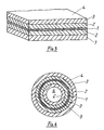
- FIG. 1 shows a perspective view of a cylindrical electrode with an electrically highly conductive conductor with a circular cross section.
- FIG. 2 shows a modification of the electrode according to FIG. 1 with an enlarged working surface.
- FIG. 3 shows a plate-shaped electrode with an electrically highly conductive conductor, which is covered on both sides by the plastic material.
- 4 shows in cross section a hollow cylindrical electrode, the electrically highly conductive conductor being covered on both sides by a plastic material.
- the electrode according to the invention consists of an electrically highly conductive conductor 1 made of metal or carbon, which is covered by an inner layer 2 made of an electrically conductive plastic material and an outer layer 3 made of an electrically conductive plastic material, the surface 4 of which forms the effective working surface of the electrode .
- an electrically highly conductive conductor 1 made of metal or carbon
- an inner layer 2 made of an electrically conductive plastic material
- an outer layer 3 made of an electrically conductive plastic material, the surface 4 of which forms the effective working surface of the electrode .
- carbon black, graphite powder, carbon fibers, graphite fibers or mixtures thereof are added to the plastic material.
- intrinsically conductive polymers can also be added.
- the inner layer 2, which surrounds the electrically highly conductive conductor 1, consists of a predominantly non-polar plastic material, which does not lose its closed and dense structure during the electrochemical processes taking place and thus guarantees protection of the electrically highly conductive conductor 1 against electrochemical or chemical influences, however ensures the necessary electrical connection between the electrically highly conductive conductor 1 and the outer layer 3.
- This outer layer 3 on the other hand, consists of a predominantly polar plastic material, which is designed in such a way that it loses its closed structure due to the electrochemical processes taking place on the surface 4 and expands to a larger volume, the effective outer and internal surface area is increased, thereby increasing the electrochemical conversion at the electrode.
- the embodiment according to FIG. 2 differs from the embodiment according to FIG. 1 in that the outer layer 3 is provided with projecting wings 5, whereby the effective working area of the electrode is increased.
- FIG. 3 shows an embodiment in which the electrically highly conductive conductor 1, which consists of a flat material, is covered on both sides by the two layers 2, 3 and is therefore, like in the embodiment according to FIGS. 1 and 2, completely encased.
- Fig. 4 shows a hollow cylindrical electrode.
- the cylindrical, electrically highly conductive conductor 1 is surrounded on both sides by cylindrical layers 2, 3 made of an electrically conductive plastic material and is therefore also completely encased.
- the electrolyte not only surrounds the outer surface 4 ', but also flows through the cylindrical cavity 6 and is therefore also in contact with the inner surface 4 ".
- the values of known electrodes are compared below with the values of the electrode according to the invention using an example.
- the stability of the electrodes was tested under electrolysis conditions in a NaCl electrolyte (5%) under galvanostatic conditions (direct current with 1mA / cm2). After every 50 hours of operation, a current-voltage curve was recorded with and without compensation for the ohmic voltage drop.
- an ethylene-vinyl acetate copolymer with 25% carbon black was mixed, plasticized and granulated in an extruder for the production of the outer layer.
- the inner layer was granulated from a mixture of low pressure polyethylene and carbon black as well as the outer layer in an extruder.
- the inner layer was first continuously extruded around an electrically highly conductive conductor made of copper, taking care to ensure a uniform layer thickness of 1.5 mm.
- the outer layer was then extruded to a thickness of 2 mm onto the inner layer.
- the first comparison electrode consisting of a copper conductor which was sheathed with a single layer of an electrically conductive plastic material which plastic material corresponded to the outer layer of the electrode according to the invention.
- the second comparative electrode was produced in the same way with the same layer thickness, but the electrically conductive plastic material corresponded to that used for the production of the inner layer of the electrode according to the invention.
- the comparison electrodes were immersed in a loop in an electrolyte, the ends were contacted and tested in the manner described above.
- the electrode according to the invention was switched as an anode under electrolysis conditions.
- the cathode of the same construction showed no significant changes in its appearance and properties over the entire duration of the test.
- the second comparison electrode was also switched as an anode under electrolysis conditions.
- the cathode of the same construction showed a slight increase in the ohmic resistance and the working potential over the entire duration of the experiment.
Landscapes
- Chemical & Material Sciences (AREA)
- Chemical Kinetics & Catalysis (AREA)
- Electrochemistry (AREA)
- Engineering & Computer Science (AREA)
- Materials Engineering (AREA)
- General Chemical & Material Sciences (AREA)
- Metallurgy (AREA)
- Organic Chemistry (AREA)
- Mechanical Engineering (AREA)
- Composite Materials (AREA)
- Electrodes For Compound Or Non-Metal Manufacture (AREA)
- Compositions Of Macromolecular Compounds (AREA)
- Battery Electrode And Active Subsutance (AREA)
- Electric Double-Layer Capacitors Or The Like (AREA)
- Inert Electrodes (AREA)
- Laminated Bodies (AREA)
Description
- Die Erfindung betrifft eine in einem Elektrolyten polarisierbare Elektrode, bestehend aus einem elektrisch hochleitfähigen Leiter, vorzugsweise aus Metall oder aus Kohlenstoff aus einer inneren, dem Leiter unmittelbar benachbarten Schicht aus einem gegebenenfalls Füllstoffe, wie Graphit oder Ruß enthaltenden, elektrisch leitfähigen Kunststoffmaterial hoher Beständigkeit gegenüber dem Elektrolyten und aus einer äußeren, dem Elektrolyten zugewandten Schicht aus einem elektrochemisch aktiven, unter Einwirkung des Elektrolyten strukturverändernden Kunststoffmaterial.
- Derartige Elektroden sind bereits bekannt und werden in elektrochemischen Prozessen, beispielsweise zur Synthese von Stoffen, zur Elektrolyse, in galvanischen Zellen zur Energiespeicherung, als Sensoren, zum Korrosionsschutz u. dgl. verwendet.
- Hierbei besteht die Forderung, daß beim Einsatz der Elektrode in einem Elektrolyten über eine bestimmte vorgegebene Mindestlebensdauer ein Mindeststromübergang zum Elektrolyten gegeben ist. Dieser Wert wird in mA/cm² angegeben. Außerdem muß über diese bestimmte, vorgegebene Lebensdauer ein vorgegebener Stromumsatz gewährleistet sein, dessen Wert in mAh/cm² festgelegt ist.
- Diese Werte werden beim Einsatz in einem bestimmten Elektrolyten durch Auswahl geeigneter Werkstoffe erzielt. Hierbei spielen natürlich auch die Materialkosten eine wesentliche Rolle. Um diese Kosten zu reduzieren, ist man in letzter Zeit dazu übergegangen, für viele Anwendungsgebiete Elektroden zu verwenden, die aus einem elektrisch hochleitfähigen Leiter, vorzugsweise aus Metall oder aus Kohlenstoff bestehen, der mit einem Kunststoff ummantelt ist, welcher durch Zusatzstoffe elektrisch leitfähig gemacht wurde.
- Da derartige Elektroden für die meisten Anwendungsgebiete eine zu geringe aktive Oberfläche des Kunststoffmantels aufweisen, um den erforderlichen Mindeststromdurchgang und Stromumsatz über die vorgegebene Lebensdauer zu gewährleisten, wurde bereits vorgeschlagen, die Oberfläche des Kunststoffmantels durch eine entsprechende Gestaltung, beispielsweise durch Aufrauhen, oder durch Anbringung einer zusätzlichen Aktivschicht, zu verbessern, welche mit geringen Anteilen an Bindemitteln und einem hohen Anteil einer elektrisch leitfähigen Komponente in einer Form aufgebracht wird, die eine Vergrößerung der aktiven Oberfläche der Elektrode bei noch annehmbarem Haftvermögen gewährleistet. Befriedigende Ergebnisse ließen sich jedoch mit diesen bekannten Elektroden nicht erzielen.
- Die DE-A-2009814 offenbart eine bipolare Elektrode für elektrochemische Zellen, welche aus einer Metallfolie, einer Haftschicht aus einem Polymer oder Copolymer von Isobutylen und einer weiteren Schicht aus dem Copolymer von Äthylen und Vinylacetat besteht, wobei beide Schichten elektronisch leitende Teilchen enthalten.
- Die vorliegende Erfindung hat sich zur Aufgabe gestellt, eine stabile und hochaktive Elektrode für einen elektrochemischen Einsatz zu schaffen, welche bei geringen Materialkosten den erforderlichen Mindeststromübergang und den erforderlichen Stromumsatz während der gesamten vorgegebenen Lebensdauer garantiert. Zur Lösung dieser Aufgabe schlägt die Erfindung vor, daß die mindestens zwei am bzw. um den Leiter angeordneten Schichten einander vollständig überdecken, daß die innere Schicht den elektrisch hochleitfähigen Leiter dicht ummantelt und daß die innere Schicht aus unpolarem Kunststoff, wie Polyäthylen, Polypropylen oder Mischungen hiervon und die äußerste Schicht aus polarem Kunststoff, wie Äthylenvinylacetat, Hart- und Weichpolyvinylchlorid, Acrylnitril-Butadien-Styrol-Terpolymer, chloriertem Polyäthylen, Nitrilkautschuk, Styrol-Butadien-Kautschuk, Halogenelastomeren oder aus Mischungen hiervon bestehen. Bei einer solchen Elektrode verliert die innere Schicht weder durch elektrochemische noch durch chemische Einflüsse ihre geschlossene Struktur und gewährleistet somit einen Schutz des elektrisch hochleitfähigen Leiters gegen elektrochemischen oder chemischen Angriff, wobei jedoch die Verbindung zur äußersten Schicht erhalten bleibt, während die äußerste Schicht durch die an der Oberfläche stattfindenden chemischen und elektrochemischen Vorgänge ihre geschlossene Struktur verliert und auf ein größeres Volumen aufgeweitet wird. Die dadurch erreichte Porosität dieser äußersten Schicht vergrößert die wirksame Oberfläche der Elektrode und begünstigt dadurch einen verstärkten elektrochemischen Umsatz an der Elektrode.
- Zweckmäßig weist die erfindungsgemäße Elektrode zwei Schichten, nämlich eine innere und eine äußere Schicht auf, es können jedoch zwischen dieser inneren und äußeren Schicht noch zusätzliche Schichten aus einem elektrisch leitfähigen Kunststoffmaterial vorgesehen sein.
- Die erfindungsgemäß ausgebildete Elektrode eignet sich besonders für einen Einsatz bei elektrochemischen und elektrokinetischen Verfahren, wie Elektrolyse, Elektrophorese und Elektroosmose, sowie als Sensor und zum Korrosionsschutz von Metallen.
- Die erfindungsgemäße Elektrode ist weiters für die der jeweils gewählten Anwendung notwendige Spannung polarisierbar, auch wenn diese Spannung über der theoretischen Elektrolysespannung von 1,23 Volt liegt oder ein Vielfaches dieser Spannung ausmacht.
- Die Beimengungen, mittels welchen die elektrische Leitfähigkeit des die Schichten bildenden Kunststoffmaterials erzielt wird, sind so zu wählen, daß sie weitgehend beständig gegen oxidativen Abbau und gegen Intercalation von Anionen sind und ihre Leitfähigkeit unter Elektrolysebedingungen weitgehend beibehalten.
- Als solche Beimengungen können auch Metallteilchen verwendet werden, jedoch ist die Verwendung solcher Metallteilchen schon aus Kostengründen nicht zweckmäßig. Dem die beiden Schichten bildenden Kunststoffmaterial können zur Erzielung der elektrischen Leitfähigkeit auch Ruß, Graphitpulver, Kohlefasern, Graphitfasern oder Mischungen hiervon beigemengt werden. Nach einem weiteren Merkmal der Erfindung besteht jedoch das die beiden Schichten bildende Kunststoffmaterial zur Erzielung der elektrischen Leitfähigkeit teilweise aus intrinsisch leitfähigen Polymeren.
- Die Zusammensetzung der Schichten soll hierbei so gewählt werden, daß der Mischungsanteil der leitfähigen Komponente zu den schlecht oder nicht leitenden Kunststoffkomponenten ein solcher ist, daß für beide Schichten gemeinsam ein spezifischer Widerstand zwischen 1 und 1000 Ohm/cm erreicht wird. Um dies zu gewährleisten, enthält gemäß einem weiteren Merkmal der Erfindung das die Schichten bildende Kunststoffmaterial Beimengungen zur Erzielung der elektrischen Leitfähigkeit in einem Anteil zwischen 5 und 70 Vol.-%, vorzugsweise von etwa 20 Vol.-%.
- Ein Merkmal der Erfindung ist schließlich, daß der elektrisch hochleitfähige Leiter aus einem flächigen Material, vorzugsweise aus einem Gitter, beispielsweise aus einem Streckmetallgitter, oder aus einem Gewebe besteht; dabei soll seine kontaktgebende Oberfläche so groß wie möglich sein. Der Querschnitt des Leiters ist der jeweilig auftretenden Stromstärke anzupassen.
- Eine einfache Herstellung der erfindungsgemäßen Elektrode ergibt sich dann, wenn die beiden aus Kunststoff bestehenden Schichten im Extrusionsverfahren, im Spritzgießen oder durch Heißpressen auf den elektrisch hochleitfähigen Leiter aufgebracht sind. Es können dann für die Herstellung der erfindungsgemäßen Elektrode bekannte übliche Kunststoffverarbeitungsmaschinen verwendet werden. Die gemischte und homogenisierte Kunststoffmasse kann als Zwischenprodukt granuliert werden oder unmittelbar formgebend verarbeitet werden.
- Optimale Ergebnisse werden dann erzielt, wenn die Dicke jeder der aus Kunsstoff bestehenden Schichten zwischen 0,2 und 5 mm beträgt.
- Die erfindungsgemäße Elektrode kann sowohl als unbegrenzt lange Bandelektrode als auch als flächige und bipolare Elektrode hergestellt werden.
- In der Zeichnung ist die Erfindung an Hand von Ausführungsbeispielen schematisch veranschaulicht. Fig. 1 zeigt in perspektivischer Darstellung eine zylinderförmige Elektrode mit einem elektrisch hochleitfähigen Leiter mit kreisförmigem Querschnitt. Fig. 2 stellt eine Abwandlung der Elektrode nach Fig. 1 mit vergrößerter Arbeitsfläche dar. Fig. 3 zeigt eine plattenförmige Elektrode mit einem elektrisch hochleitfähigen Leiter, der beidseitig vom Kunststoffmaterial abgedeckt ist. Fig. 4 stellt im Querschnitt eine hohlzylindrische Elektrode dar, wobei der elektrisch hochleitfähige Leiter beidseitig von einem Kunststoffmaterial abgedeckt ist.
- Die erfindungsgemäße Elektrode besteht aus einem elektrisch hochleitfähigen Leiter 1 aus Metall oder aus Kohlenstoff, der von einer inneren Schicht 2 aus einem elektrisch leitfähigen Kunststoffmaterial und aus einer äußeren Schicht 3 aus einem elektrisch leitfähigen Kunststoffmaterial abgedeckt ist, deren Oberfläche 4 die wirksame Arbeitsfläche der Elektrode bildet. Zur Erzielung der elektrischen Leitfähigkeit beider Kunststoffschichten 2, 3 sind dem Kunststoffmaterial Ruß, Graphitpulver, Kohlefasern, Graphitfasern oder Mischungen hiervon beigemengt. Es kann aber auch eine Beimengung von intrinsisch leitfähigen Polymeren erfolgen.
- Die innere Schicht 2, welche den elektrisch hochleitfähigen Leiter 1 umgibt, besteht aus einem überwiegend unpolaren Kunststoffmaterial, welches bei den stattfindenden elektrochemischen Vorgängen seine geschlossene und dichte Struktur nicht verliert und somit einen Schutz des elektrisch hochleitfähigen Leiters 1 gegen elektrochemische oder chemische Einflüsse gewährleistet, jedoch die notwendige elektrische Verbindung zwischen dem elektrisch hochleitfähigen Leiter 1 und der äußeren Schicht 3 sicherstellt.
- Diese äußere Schicht 3 hingegen besteht aus einem überwiegend polaren Kunststoffmaterial, welches derart beschaffen ist, daß es durch die an der Oberfläche 4 stattfindenden elektrochemischen Vorgänge seine geschlossene Struktur verliert und sich auf ein größeres Volumen aufweitet, wobei durch die dabei entstehende Porosität die wirksame äußere und innere Oberfläche vergrößert und dadurch der elektrochemische Umsatz an der Elektrode verstärkt wird.
- Die Ausführungsform nach Fig. 2 unterscheidet sich von der Ausführungsform nach Fig. 1 dadurch, daß die äußere Schicht 3 mit abstehenden Flügeln 5 versehen ist, wodurch die wirksame Arbeitsfläche der Elektrode vergrößert wird.
- Fig. 3 zeigt eine Ausführungsform, bei welcher der aus einem flächigen Material bestehende elektrisch hochleitfähige Leiter 1 beidseitig von den beiden Schichten 2,3 bedeckt und daher, ebenso wie bei der Ausführungsform nach den Fig. 1 und 2, vollständig ummantelt ist.
- Fig. 4 zeigt eine hohlzylindrische Elektrode. Der zylinderförmige, elektrisch hochleitfähige Leiter 1 ist hierbei beidseitig von zylindrischen Schichten 2,3 aus einem elektrisch leitfähigen Kunststoffmaterial umgeben und daher gleichfalls vollständig ummantelt. Der Elektrolyt umgibt nicht nur die äußere Oberfläche 4′, sondern durchströmt auch den zylindrischen Hohlraum 6 und steht daher auch mit der inneren Oberfläche 4" in Berührung.
- Im folgenden werden an Hand eines Beispieles die Werte bekannter Elektroden mit den Werten der erfindungsgemäßen Elektrode verglichen. Die Prüfung der Stabilität der Elektroden erfolgte hierbei unter Elektrolysebedingungen in einem NaCl-Elektrolyten (5 %) unter galvanostatischen Bedingungen (Gleichstrom mit 1mA/cm²). Nach jeweils 50 Betriebsstunden wurde eine Strom-Spannungskurve mit und ohne Kompensation des Ohm'schen Spannungsabfalles aufgenommen.
- Zur Herstellung der erfindungsgemäßen Elektrode wurden in einem Extruder für die Herstellung der äußeren Schicht ein Äthylenvinylacetat-Copolymer mit 25% Ruß gemischt, plastifiziert und granuliert.
- Die innere Schicht wurde aus einer Mischung aus Niederdruck-Polyäthylen und Ruß ebenso wie die äußere Schicht in einem Extruder granuliert.
- Anschließend wurde um einen aus Kupfer bestehenden elektrisch hochleitfähigen Leiter zunächst die innere Schicht kontinuierlich extrudiert, wobei auf eine gleichmäßige Schichtdicke von 1,5 mm geachtet wurde. In einem zweiten Arbeitsgang wurde dann auf die innere Schicht die äußere Schicht in einer Dicke von 2 mm extrudiert.
- Als Vergleichselektroden wurden Einschichtelektroden gleicher Form hergestellt, wobei die erste Vergleichselektrode aus einem Kupferleiter bestand, der mit einer einzigen Schicht aus einem elektrisch leitfähigen Kunststoffmaterial ummantelt wurde, welches Kunststoffmaterial der äußeren Schicht der erfindungsgemäßen Elektrode entsprach. Die zweite Vergleichselektrode wurde in gleicher Weise mit derselben Schichtdicke hergestellt, wobei jedoch das elektrisch leitfähige Kunststoffmaterial jenem entsprach, das für die Herstellung der inneren Schicht der erfindungsgemäßen Elektrode verwendet wurde.
- Die Vergleichselektroden wurden als Schleife in einen Elektrolyten getaucht, die Enden kontaktiert und in der oben beschriebenen Weise getestet.
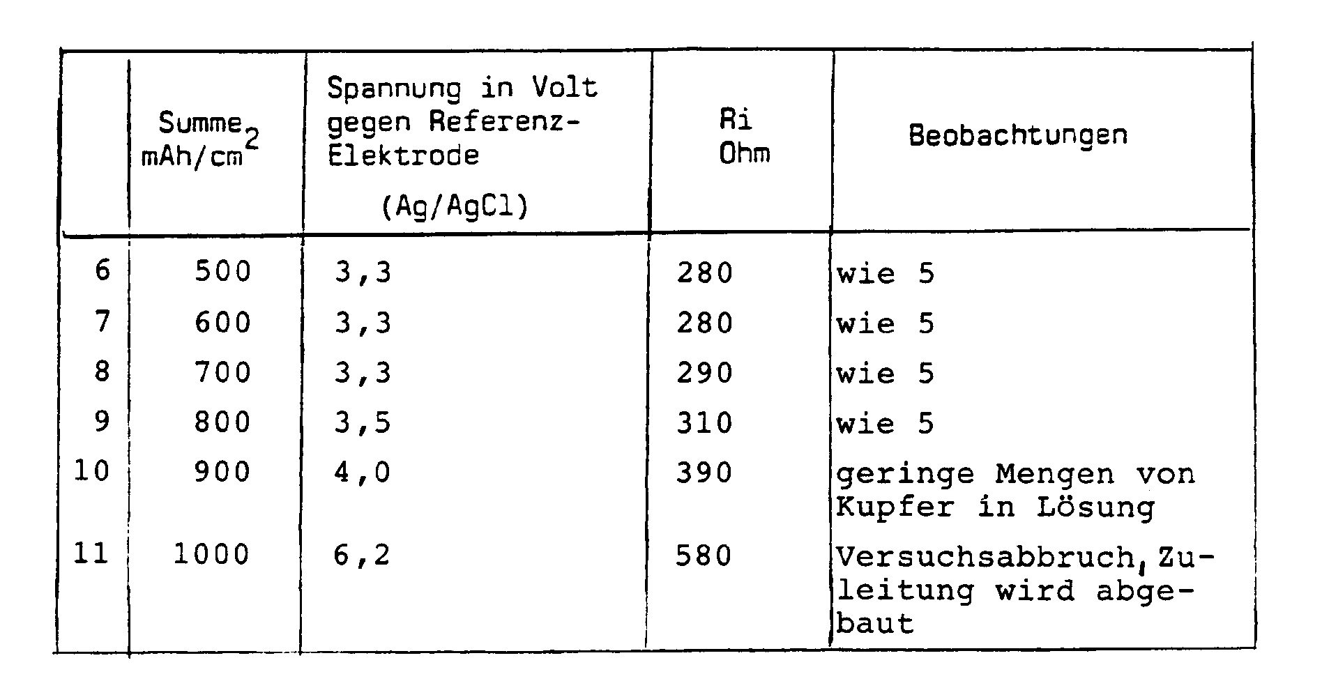
- In den folgenden Tabellen sind die Testergebnisse enthalten.
-
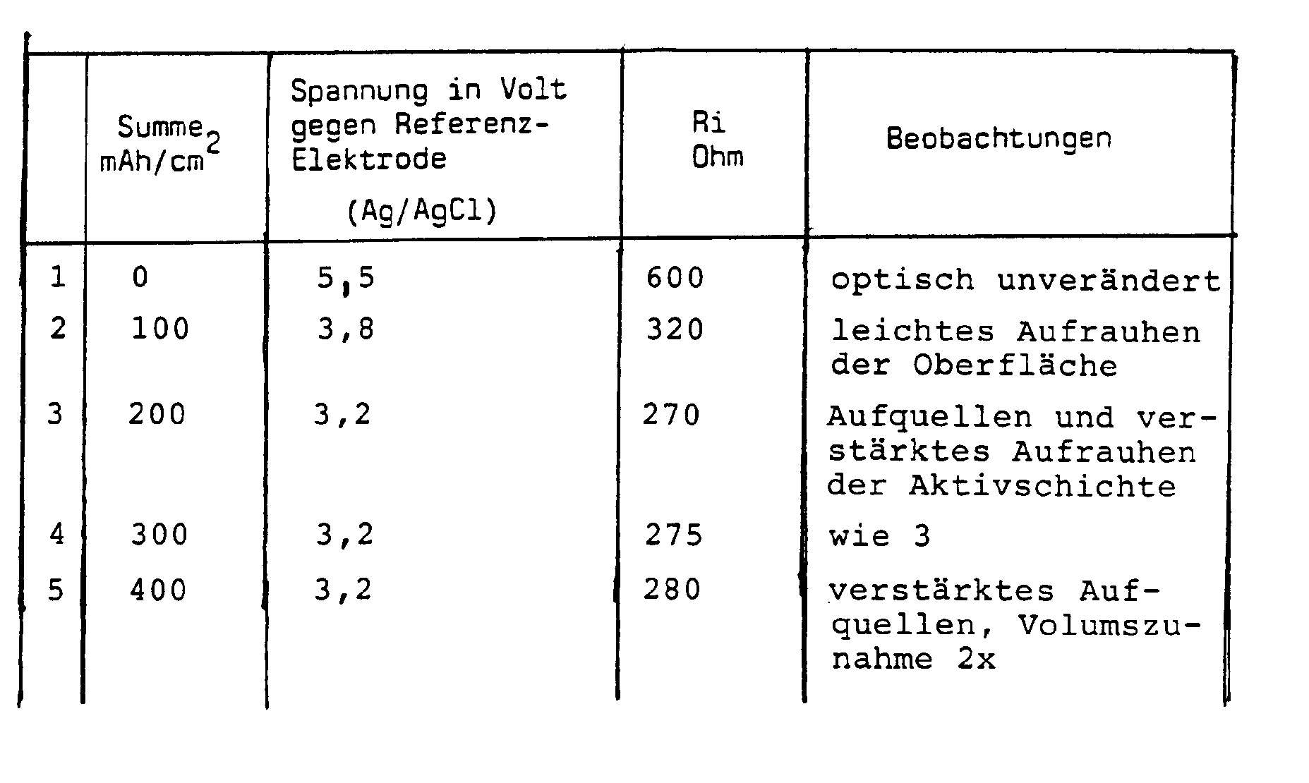
- Die erfindungsgemäße Elektrode wurde hierbei als Anode unter Elektrolysebedingungen geschaltet. Die Kathode derselben Konstruktion zeigte über die gesamte Versuchsdauer keine nennenswerten Veränderungen ihres Aussehens und ihrer Eigenschaften.
-

-

- Auch die zweite Vergleichselektrode wurde als Anode unter Elektrolysebedingungen geschaltet.
- Die Kathode derselben Konstruktion zeigte über die gesamte Versuchsdauer geringfügigen Anstieg des Ohm'schen Widerstandes und des Arbeitspotentials.
Claims (4)
- In einem Elektrolyten polarisierbare Elektrode, bestehend aus einem elektrisch hochleitfähigen Leiter (1), vorzugsweise aus Metall oder Kohlenstoff, aus einer inneren, dem Leiter (1) unmittelbar benachbarten Schicht (2) aus einem gegebenenfalls Füllstoffe, wie Graphit oder Ruß enthaltenden, elektrisch leitfähigen Kunststoffmaterial hoher Beständigkeit gegenüber dem Elektrolyten und aus einer äußeren, dem Elektrolyten zugewandten Schicht (3) aus einem elektrochemisch aktiven, unter Einwirkung des Elektrolyten strukturverändernden Kunststoffmaterial, dadurch gekennzeichnet, daß die mindestens zwei am bzw. um den Leiter (1) angeordneten Schichten (2, 3) einander vollständig überdecken, daß die innere Schicht (2) den elektrisch hochleitfähigen Leiter (1) dicht umhüllt und daß die innere Schicht (2) aus unpolarem Kunststoff, wie Polyäthylen, Polypropylen oder Mischungen hiervon und die äußerste Schicht (3) aus polarem Kunststoff, wie Äthylenvinylacetat, Hart- und Weichpolyvinylchlorid, Acrylnitril-Butadien-Styrol-Terpolymer, chloriertem Polyäthylen, Nitrilkautschuk, Styrol-Butadien-Kautschuk, Halogenelastomeren oder aus Mischungen hiervon bestehen.
- Elektrode nach Anspruch 1, dadurch gekennzeichnet, daß das die Schichten (2, 3) bildende Kunststoffmaterial zur Erzielung der elektrischen Leitfähigkeit teilweise aus intrinsisch leitfähigen Polymeren besteht.
- Elektrode nach einem der Ansprüche 1 oder 2, dadurch gekennzeichnet, daß das die Schichten (2, 3) bildende Kunststoffmaterial Beimengungen zur Erzielung der elektrischen Leitfähigkeit in einem Anteil zwischen 5 und 70 Vol.-%, vorzugsweise von etwa 20 Vol.-% enthält.
- Elektrode nach einem der Ansprüche 1 bis 3, dadurch gekennzeichnet, daß der elektrisch hochleitfähige Leiter (1) aus einem flächigen Material, vorzugsweise aus einem Gitter, beispielsweise einem Streckmetallgitter, oder aus einem Gewebe besteht.
Applications Claiming Priority (2)
| Application Number | Priority Date | Filing Date | Title |
|---|---|---|---|
| AT703/88 | 1988-03-15 | ||
| AT0070388A AT390274B (de) | 1988-03-15 | 1988-03-15 | Elektrode |
Publications (2)
| Publication Number | Publication Date |
|---|---|
| EP0333700A1 EP0333700A1 (de) | 1989-09-20 |
| EP0333700B1 true EP0333700B1 (de) | 1994-11-02 |
Family
ID=3497585
Family Applications (1)
| Application Number | Title | Priority Date | Filing Date |
|---|---|---|---|
| EP89890075A Expired - Lifetime EP0333700B1 (de) | 1988-03-15 | 1989-03-15 | Elektrode |
Country Status (14)
| Country | Link |
|---|---|
| US (1) | US4966675A (de) |
| EP (1) | EP0333700B1 (de) |
| AT (1) | AT390274B (de) |
| CA (1) | CA1338404C (de) |
| CZ (1) | CZ283378B6 (de) |
| DE (1) | DE58908574D1 (de) |
| DK (1) | DK70989A (de) |
| ES (1) | ES2064488T3 (de) |
| HU (1) | HU207538B (de) |
| LT (1) | LT3291B (de) |
| LV (1) | LV10793B (de) |
| RU (1) | RU2014368C1 (de) |
| SK (1) | SK278778B6 (de) |
| YU (1) | YU42289A (de) |
Families Citing this family (25)
| Publication number | Priority date | Publication date | Assignee | Title |
|---|---|---|---|---|
| US5078936A (en) * | 1989-08-16 | 1992-01-07 | E. I. Dupont De Nemours And Company | Method for producing a conductive polyimide structure |
| WO1992019793A1 (fr) * | 1991-04-15 | 1992-11-12 | Nv Raychem S.A. | Procede de protection electrique d'objet en metal, electrode de mise a la terre utilisee pour mettre en ×uvre le procede et composition d'electrode de mise a la terre |
| GB9116114D0 (en) * | 1991-07-25 | 1991-09-11 | Raychem Ltd | Corrosion protection system |
| US5754329A (en) * | 1992-12-22 | 1998-05-19 | Monsanto Company | Electrochromic display laminates |
| US5413739A (en) * | 1992-12-22 | 1995-05-09 | Coleman; James P. | Electrochromic materials and displays |
| US5948218A (en) * | 1994-04-21 | 1999-09-07 | N.V. Raychem S.A. | Corrosion protection system |
| US5876633A (en) * | 1995-12-26 | 1999-03-02 | Monsanto Company | Electrochromic metal oxides |
| US5891511A (en) * | 1995-12-26 | 1999-04-06 | Monsanto Company | Addition of color to electrochromic displays |
| WO1997023578A1 (en) * | 1995-12-26 | 1997-07-03 | Monsanto Company | Electrochromic tin oxide |
| GB2309978A (en) * | 1996-02-09 | 1997-08-13 | Atraverda Ltd | Titanium suboxide electrode; cathodic protection |
| ATE213227T1 (de) * | 1996-07-12 | 2002-02-15 | November Ag Molekulare Medizin | Verfahren und vorrichtung zur aufreinigung und anreicherung von molekülen |
| GB2337150B (en) * | 1998-05-07 | 2000-09-27 | Nat Power Plc | Carbon based electrodes |
| GB9915420D0 (en) * | 1999-07-01 | 1999-09-01 | Atraverda Ltd | Electrode |
| GB0005377D0 (en) | 2000-03-06 | 2000-04-26 | Atraverda Ltd | Electrode |
| US7804044B2 (en) * | 2000-12-23 | 2010-09-28 | Braincom Ag | Heating device and method for the production thereof and heatable object and method for producing same |
| NO321256B1 (no) * | 2002-08-26 | 2006-04-10 | Oro As | Elektrodekonstruksjoner, samt anvendelse derav |
| DE50311249D1 (de) * | 2002-10-23 | 2009-04-16 | Braincom Ag | Flächenheizung, verfahren zu deren herstellung und heizbarer gegenstand sowie sitzbelegungserkennung, sitz damit und sitzbelegungserkennungsverfahren |
| US7655327B2 (en) * | 2003-12-29 | 2010-02-02 | Translucent, Inc. | Composition comprising rare-earth dielectric |
| RU2345958C1 (ru) * | 2007-09-19 | 2009-02-10 | Государственное Образовательное Учреждение Высшего Профессионального Образования "Дагестанский Государственный Технический Университет" (Дгту) | Способ умягчения воды |
| RU2417955C1 (ru) * | 2009-10-05 | 2011-05-10 | Открытое Акционерное Общество "Научно-исследовательский институт по нефтепромысловой химии" (ОАО "НИИнефтепромхим") | Состав для предотвращения неорганических отложений |
| RU2417954C1 (ru) * | 2009-10-05 | 2011-05-10 | Открытое Акционерное Общество "Научно-исследовательский институт по нефтепромысловой химии" (ОАО "НИИнефтепромхим") | Состав для предотвращения неорганических отложений |
| US8649704B2 (en) * | 2009-11-20 | 2014-02-11 | Xerox Corporation | Bias charging overcoat |
| US8768219B2 (en) * | 2009-11-20 | 2014-07-01 | Xerox Corporation | Bias charging overcoat |
| CN103726090A (zh) * | 2012-10-11 | 2014-04-16 | 中国科学院大连化学物理研究所 | 一种用于光电解用的α-Fe2O3光阳极的制备方法 |
| PL248346B1 (pl) * | 2023-04-06 | 2025-12-01 | Uniwersytet Łódzki | Korpus elektrody dyskowej do pomiarów zwielokrotnionych |
Family Cites Families (13)
| Publication number | Priority date | Publication date | Assignee | Title |
|---|---|---|---|---|
| GB200363A (en) * | 1922-07-12 | 1923-07-12 | Gen Electric | Improvements in and relating to electrical induction apparatus, such as transformers |
| US3061494A (en) | 1959-10-05 | 1962-10-30 | Boeing Co | Process of chemical milling and acid aqueous bath used therefor |
| BE592862A (de) * | 1960-07-04 | |||
| US3193412A (en) * | 1962-02-20 | 1965-07-06 | Electric Storage Battery Co | Electric battery |
| US3423247A (en) * | 1963-06-07 | 1969-01-21 | Union Carbide Corp | Porous conductive electrode having at least two zones |
| US4135039A (en) * | 1969-02-21 | 1979-01-16 | Unigate, Limited | Electrode structures and electrodes therefrom for use in electrolytic cells or batteries |
| US3629007A (en) * | 1969-08-06 | 1971-12-21 | Us Army | Reserve battery electrodes using bonded active materials |
| GB1373711A (en) * | 1971-01-25 | 1974-11-13 | Zito Co | Electroconductive materials suitable for batteries and battery components |
| NL7706998A (nl) * | 1977-06-24 | 1978-12-28 | Electrochem Energieconversie | Poreuze elektrode. |
| JPS59215668A (ja) * | 1983-05-24 | 1984-12-05 | Meidensha Electric Mfg Co Ltd | 亜鉛−臭素電池の電極 |
| JPS61284059A (ja) * | 1985-06-10 | 1986-12-15 | Meidensha Electric Mfg Co Ltd | 多孔質カ−ボンプラスチツク電極の製造方法 |
| DE3610388A1 (de) * | 1986-03-27 | 1987-10-01 | Bernhard Dr Wessling | Stabile elektroden auf basis makromolekularer werkstoffe und verfahren zu ihrer verwendung |
| US4957612A (en) * | 1987-02-09 | 1990-09-18 | Raychem Corporation | Electrodes for use in electrochemical processes |
-
1988
- 1988-03-15 AT AT0070388A patent/AT390274B/de not_active IP Right Cessation
-
1989
- 1989-02-15 DK DK070989A patent/DK70989A/da not_active Application Discontinuation
- 1989-02-20 HU HU89821A patent/HU207538B/hu not_active IP Right Cessation
- 1989-02-27 YU YU00422/89A patent/YU42289A/xx unknown
- 1989-03-13 SK SK1565-89A patent/SK278778B6/sk unknown
- 1989-03-13 CZ CS891565A patent/CZ283378B6/cs not_active IP Right Cessation
- 1989-03-14 CA CA000593633A patent/CA1338404C/en not_active Expired - Fee Related
- 1989-03-14 RU SU894613667A patent/RU2014368C1/ru active
- 1989-03-15 ES ES89890075T patent/ES2064488T3/es not_active Expired - Lifetime
- 1989-03-15 US US07/324,369 patent/US4966675A/en not_active Expired - Fee Related
- 1989-03-15 EP EP89890075A patent/EP0333700B1/de not_active Expired - Lifetime
- 1989-03-15 DE DE58908574T patent/DE58908574D1/de not_active Expired - Fee Related
-
1993
- 1993-04-08 LV LVP-93-236A patent/LV10793B/xx unknown
- 1993-06-04 LT LTIP619A patent/LT3291B/lt not_active IP Right Cessation
Also Published As
| Publication number | Publication date |
|---|---|
| LV10793B (en) | 1995-10-20 |
| EP0333700A1 (de) | 1989-09-20 |
| HU207538B (en) | 1993-04-28 |
| CZ283378B6 (cs) | 1998-04-15 |
| LV10793A (lv) | 1995-08-20 |
| DE58908574D1 (de) | 1994-12-08 |
| US4966675A (en) | 1990-10-30 |
| AT390274B (de) | 1990-04-10 |
| RU2014368C1 (ru) | 1994-06-15 |
| YU42289A (en) | 1990-06-30 |
| HUT55059A (en) | 1991-04-29 |
| LTIP619A (en) | 1994-12-27 |
| CA1338404C (en) | 1996-06-18 |
| DK70989D0 (da) | 1989-02-15 |
| SK156589A3 (en) | 1998-02-04 |
| ATA70388A (de) | 1989-09-15 |
| ES2064488T3 (es) | 1995-02-01 |
| SK278778B6 (sk) | 1998-02-04 |
| DK70989A (da) | 1989-09-16 |
| CZ156589A3 (en) | 1997-11-12 |
| LT3291B (en) | 1995-06-26 |
Similar Documents
| Publication | Publication Date | Title |
|---|---|---|
| EP0333700B1 (de) | Elektrode | |
| DE3871818T2 (de) | Elektroden zur verwendung in elektrochemischen verfahren. | |
| DE3440617C1 (de) | Antistatische bzw. elektrisch halbleitende thermoplastische Polymerblends,Verfahren zu deren Herstellung und deren Verwendung | |
| DE2459627C2 (de) | Medizinische Elektrode | |
| DE3147192C2 (de) | ||
| DE2220247C3 (de) | Sauerstoff-Anode | |
| DE3000777A1 (de) | Kondensator mit elektrischer doppelschicht | |
| DE2163569A1 (de) | Elektrische Zelle mit sie nach außen verschließenden Trennelementen | |
| DE69131787T2 (de) | Verfahren zur herstellung einer elektrischen vorrichtung | |
| DE10039174B4 (de) | Elektrode für einen elektrischen Doppelschichtkondensator und Aufschlemmung zur Bildung derselben | |
| DE3026778A1 (de) | Elektrode | |
| EP1924125A1 (de) | Heizbare Folie | |
| DE2524774C3 (de) | Negative Kobalt-Elektrode für alkalische Akkumulatoren und Verfahren zu ihrer Herstellung | |
| DE2929303A1 (de) | Zinkelektrode und verfahren zu ihrer herstellung | |
| DE2008548B2 (de) | Positive Elektrode für wiederaufladbare elektrische Zink-Halogenzellen eines Akkumulators | |
| EP0244626B1 (de) | Elektrode sowie deren Verwendung | |
| DE3413303C2 (de) | ||
| DE2311957C3 (de) | Verfahren zur Herstellung eines Elektrodengefüges für elektrische Zellen | |
| DE69121594T2 (de) | Verfahren zum elektrischen schutz von metallobjekten, erdungselektrode dafür und zusammensetzung der erdungselektrode | |
| DE2243187A1 (de) | Kathode fuer galvanisches element und verfahren zu deren herstellung | |
| DE2818559A1 (de) | Aus einer poroesen membran und einem traeger bestehender verbundkoerper und verfahren zu seiner herstellung | |
| EP3035771B1 (de) | Elektrisch leitfähiges polymeres flächengebilde | |
| EP1698372B1 (de) | Verfahren zur Herstellung eines elektrisch kontaktierbaren Bereichs auf einem dotierten Polymer und nach dem Verfahren herstellbare Elektroden | |
| DE1932025A1 (de) | Poroese Elektrode und Verfahren zur elektrochemischen Umwandlung in Elektrolyse-Zellen | |
| DE1931954C3 (de) | Elektrode, die mindestens teilweise aus porösem Material besteht, für elektrochemische Umwandlungen in einer elektrolytischen Zelle |
Legal Events
| Date | Code | Title | Description |
|---|---|---|---|
| PUAI | Public reference made under article 153(3) epc to a published international application that has entered the european phase |
Free format text: ORIGINAL CODE: 0009012 |
|
| AK | Designated contracting states |
Kind code of ref document: A1 Designated state(s): BE CH DE ES FR GB GR IT LI LU NL SE |
|
| 17P | Request for examination filed |
Effective date: 19891107 |
|
| 17Q | First examination report despatched |
Effective date: 19911025 |
|
| RAP3 | Party data changed (applicant data changed or rights of an application transferred) |
Owner name: STEININGER, KARL-HEINZ, DIPL.-ING.DR.TECHN. |
|
| GRAA | (expected) grant |
Free format text: ORIGINAL CODE: 0009210 |
|
| AK | Designated contracting states |
Kind code of ref document: B1 Designated state(s): BE CH DE ES FR GB GR IT LI LU NL SE |
|
| PG25 | Lapsed in a contracting state [announced via postgrant information from national office to epo] |
Ref country code: GR Free format text: LAPSE BECAUSE OF FAILURE TO SUBMIT A TRANSLATION OF THE DESCRIPTION OR TO PAY THE FEE WITHIN THE PRESCRIBED TIME-LIMIT Effective date: 19941102 Ref country code: BE Effective date: 19941102 |
|
| REF | Corresponds to: |
Ref document number: 58908574 Country of ref document: DE Date of ref document: 19941208 |
|
| GBT | Gb: translation of ep patent filed (gb section 77(6)(a)/1977) |
Effective date: 19941215 |
|
| ITF | It: translation for a ep patent filed | ||
| REG | Reference to a national code |
Ref country code: ES Ref legal event code: FG2A Ref document number: 2064488 Country of ref document: ES Kind code of ref document: T3 |
|
| PG25 | Lapsed in a contracting state [announced via postgrant information from national office to epo] |
Ref country code: SE Effective date: 19950202 |
|
| ET | Fr: translation filed | ||
| PG25 | Lapsed in a contracting state [announced via postgrant information from national office to epo] |
Ref country code: LU Free format text: LAPSE BECAUSE OF NON-PAYMENT OF DUE FEES Effective date: 19950331 |
|
| PLBE | No opposition filed within time limit |
Free format text: ORIGINAL CODE: 0009261 |
|
| STAA | Information on the status of an ep patent application or granted ep patent |
Free format text: STATUS: NO OPPOSITION FILED WITHIN TIME LIMIT |
|
| 26N | No opposition filed | ||
| PGFP | Annual fee paid to national office [announced via postgrant information from national office to epo] |
Ref country code: FR Payment date: 20010309 Year of fee payment: 13 Ref country code: CH Payment date: 20010309 Year of fee payment: 13 |
|
| PGFP | Annual fee paid to national office [announced via postgrant information from national office to epo] |
Ref country code: GB Payment date: 20010314 Year of fee payment: 13 |
|
| PGFP | Annual fee paid to national office [announced via postgrant information from national office to epo] |
Ref country code: NL Payment date: 20010330 Year of fee payment: 13 |
|
| PGFP | Annual fee paid to national office [announced via postgrant information from national office to epo] |
Ref country code: ES Payment date: 20010409 Year of fee payment: 13 |
|
| REG | Reference to a national code |
Ref country code: GB Ref legal event code: IF02 |
|
| PG25 | Lapsed in a contracting state [announced via postgrant information from national office to epo] |
Ref country code: GB Free format text: LAPSE BECAUSE OF NON-PAYMENT OF DUE FEES Effective date: 20020315 |
|
| PGFP | Annual fee paid to national office [announced via postgrant information from national office to epo] |
Ref country code: DE Payment date: 20020315 Year of fee payment: 14 |
|
| PG25 | Lapsed in a contracting state [announced via postgrant information from national office to epo] |
Ref country code: ES Free format text: LAPSE BECAUSE OF NON-PAYMENT OF DUE FEES Effective date: 20020316 |
|
| PG25 | Lapsed in a contracting state [announced via postgrant information from national office to epo] |
Ref country code: LI Free format text: LAPSE BECAUSE OF NON-PAYMENT OF DUE FEES Effective date: 20020331 Ref country code: CH Free format text: LAPSE BECAUSE OF NON-PAYMENT OF DUE FEES Effective date: 20020331 |
|
| PG25 | Lapsed in a contracting state [announced via postgrant information from national office to epo] |
Ref country code: NL Free format text: LAPSE BECAUSE OF NON-PAYMENT OF DUE FEES Effective date: 20021001 |
|
| GBPC | Gb: european patent ceased through non-payment of renewal fee |
Effective date: 20020315 |
|
| REG | Reference to a national code |
Ref country code: CH Ref legal event code: PL |
|
| PG25 | Lapsed in a contracting state [announced via postgrant information from national office to epo] |
Ref country code: FR Free format text: LAPSE BECAUSE OF NON-PAYMENT OF DUE FEES Effective date: 20021129 |
|
| NLV4 | Nl: lapsed or anulled due to non-payment of the annual fee |
Effective date: 20021001 |
|
| REG | Reference to a national code |
Ref country code: FR Ref legal event code: ST |
|
| PG25 | Lapsed in a contracting state [announced via postgrant information from national office to epo] |
Ref country code: DE Free format text: LAPSE BECAUSE OF NON-PAYMENT OF DUE FEES Effective date: 20031001 |
|
| REG | Reference to a national code |
Ref country code: ES Ref legal event code: FD2A Effective date: 20030410 |
|
| PG25 | Lapsed in a contracting state [announced via postgrant information from national office to epo] |
Ref country code: IT Free format text: LAPSE BECAUSE OF NON-PAYMENT OF DUE FEES;WARNING: LAPSES OF ITALIAN PATENTS WITH EFFECTIVE DATE BEFORE 2007 MAY HAVE OCCURRED AT ANY TIME BEFORE 2007. THE CORRECT EFFECTIVE DATE MAY BE DIFFERENT FROM THE ONE RECORDED. Effective date: 20050315 |