EP0333669B1 - Anlasser für Brennkraftmaschinen - Google Patents
Anlasser für Brennkraftmaschinen Download PDFInfo
- Publication number
- EP0333669B1 EP0333669B1 EP89830097A EP89830097A EP0333669B1 EP 0333669 B1 EP0333669 B1 EP 0333669B1 EP 89830097 A EP89830097 A EP 89830097A EP 89830097 A EP89830097 A EP 89830097A EP 0333669 B1 EP0333669 B1 EP 0333669B1
- Authority
- EP
- European Patent Office
- Prior art keywords
- main shaft
- starter according
- movable component
- starter
- pinion
- Prior art date
- Legal status (The legal status is an assumption and is not a legal conclusion. Google has not performed a legal analysis and makes no representation as to the accuracy of the status listed.)
- Expired - Lifetime
Links
- 239000007858 starting material Substances 0.000 title claims abstract description 35
- 238000002485 combustion reaction Methods 0.000 title claims abstract description 10
- 230000007246 mechanism Effects 0.000 claims description 3
- 230000000694 effects Effects 0.000 claims description 2
- 230000008878 coupling Effects 0.000 description 3
- 238000010168 coupling process Methods 0.000 description 3
- 238000005859 coupling reaction Methods 0.000 description 3
- 230000009471 action Effects 0.000 description 2
- 239000002184 metal Substances 0.000 description 2
- 230000002093 peripheral effect Effects 0.000 description 2
- 230000004913 activation Effects 0.000 description 1
- 230000015572 biosynthetic process Effects 0.000 description 1
- 238000006243 chemical reaction Methods 0.000 description 1
- 230000000295 complement effect Effects 0.000 description 1
- 230000036461 convulsion Effects 0.000 description 1
- 230000007423 decrease Effects 0.000 description 1
- 230000003247 decreasing effect Effects 0.000 description 1
- 238000005755 formation reaction Methods 0.000 description 1
- 230000005484 gravity Effects 0.000 description 1
- 238000004519 manufacturing process Methods 0.000 description 1
- 239000000463 material Substances 0.000 description 1
- 230000009467 reduction Effects 0.000 description 1
- 230000000452 restraining effect Effects 0.000 description 1
Images

Classifications
-
- F—MECHANICAL ENGINEERING; LIGHTING; HEATING; WEAPONS; BLASTING
- F02—COMBUSTION ENGINES; HOT-GAS OR COMBUSTION-PRODUCT ENGINE PLANTS
- F02N—STARTING OF COMBUSTION ENGINES; STARTING AIDS FOR SUCH ENGINES, NOT OTHERWISE PROVIDED FOR
- F02N15/00—Other power-operated starting apparatus; Component parts, details, or accessories, not provided for in, or of interest apart from groups F02N5/00 - F02N13/00
- F02N15/02—Gearing between starting-engines and started engines; Engagement or disengagement thereof
- F02N15/022—Gearing between starting-engines and started engines; Engagement or disengagement thereof the starter comprising an intermediate clutch
- F02N15/023—Gearing between starting-engines and started engines; Engagement or disengagement thereof the starter comprising an intermediate clutch of the overrunning type
-
- Y—GENERAL TAGGING OF NEW TECHNOLOGICAL DEVELOPMENTS; GENERAL TAGGING OF CROSS-SECTIONAL TECHNOLOGIES SPANNING OVER SEVERAL SECTIONS OF THE IPC; TECHNICAL SUBJECTS COVERED BY FORMER USPC CROSS-REFERENCE ART COLLECTIONS [XRACs] AND DIGESTS
- Y10—TECHNICAL SUBJECTS COVERED BY FORMER USPC
- Y10T—TECHNICAL SUBJECTS COVERED BY FORMER US CLASSIFICATION
- Y10T74/00—Machine element or mechanism
- Y10T74/13—Machine starters
- Y10T74/131—Automatic
- Y10T74/133—Holders
Definitions
- the present invention relates to starters for internal combustion engines and particularly concerns a starter of the type comprising:
- a starter of the type specified above is known, for example from United States patent N0. 4,325,265.
- a somewhat similar arrangement is known also from GB-A-561440.
- starters differ from prior art starters (such as those known, for example, from British patent No. 511,289, German patent No. 717,864, French patent No. 843,175 and United States patents Nos. 2,787,910, 3,656,355 and 4395923 in that they provide for the use of means which act centrifugally, not for disengaging the pinion from its advanced starting position but for keeping the pinion in that position until the internal combustion engine has safely been started.
- prior art starters such as those known, for example, from British patent No. 511,289, German patent No. 717,864, French patent No. 843,175 and United States patents Nos. 2,787,910, 3,656,355 and 4395923 in that they provide for the use of means which act centrifugally, not for disengaging the pinion from its advanced starting position but for keeping the pinion in that position until the internal combustion engine has safely been started.
- the object of the present invention is to provide a starter which is further improved, particularly as regards the reduction of its dimensions (and therefore of its weight) and its structural simplification, which provides cost advantages in the manufacture of the product on an industrial scale.
- a starter generally indicated 1 is intended for association with an electric starter motor (not illustrated) so as to enable the starting of an internal combustion engine of which the ring gear C keyed to the shaft is partially visible in Figures 1 and 2.
- the main shaft of the starter 1 is indicated 2 and has a sprocket 3 keyed firmly to one end thereof, for rotation by the electric motor (not illustrated) already referred to above ⁇ causing the rotation of the shaft 2 about its axis X2.
- the shaft 2 Immediately behind the sprocket 3, the shaft 2 has a portion 4 which has a helical thread with several starts.
- the shaft 2 Immediately downstream of the threaded portion 4, the shaft 2 has a shoulder 5 which constitutes one side of an annular groove 6.
- the groove 6 On its side opposite the shoulder 5, the groove 6 is defined by another shoulder 7, downstream of which the shaft 2 continues into a substantially cylindrical portion 8.
- a generally-cylindrical, movable component 10 is slidably fitted around the shaft 2 with the interposition of a bush 9 of self-lubricating material which surrounds the cylindrical portion 8.
- the component 10 is constituted essentially by a cover or casing 11 of pressed metal which (starting from the end facing towards the sprocket 3) encloses the following elements:
- the function of the screw-thread coupling between the toothed portion 4 of the shaft 2 and the internal toothing of the annular body 12 is to cause a movement of the movable component 10 generally (and of the pinion 14 carried thereby) towards an advanced position in which it is meshed with the ring gear C, as shown in Figure 2, as a result of the rotation of the shaft 2.
- This advance of the movable element 10 occurs against a resilient biassing force exerted by a helical spring 17 fitted around an annular appendage 14a of the pinion 14, which surrounds the cylindrical portion 8 of the shaft 2. More precisely, the spring 17 acts between the pinion 14 and an annular end member 18 fitted around the end of the cylindrical portion 8 of the shaft 2 and held in position by a resilient ring 19 (or like stop member) snap-engaged in a corresponding groove 20 in the shaft 2.
- the shoulder 5 which is frusto-conical and tapers towards the end of the shaft 2 on which the stop end member 18 is fitted, and the groove 6 as a whole, therefore define ⁇ within the shaft 2 ⁇ a taper in the direction of movement of the movable component 10 towards its advanced, meshed position.
- the taper of the shoulder 5 is preferably selected so that the generatrices of the theoretical conic surface defined by the shoulder are at an angle ⁇ of approximately 80° to the axis X2 of the shaft 2. Moreover, it is preferable for the working of the groove 6 to be such that its diameter is slightly less than the inner or base diameter of the threading 4.
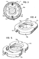
- the two centrifugal bodies or masses 13a and 13b are generally annular in shape. They are each constituted essentially by a curved portion 113 which faces the wall of the sleeve 15 (and thus faces away from the shaft 2) and an arcuate portion 114 intended to embrace the shaft 2.
- the arcuate portions 114 have respective thinner central sections 116, in correspondence with which the bodies 13a, 13b are slidably coupled together.
- the bodies 13a, 13b are also clearly asymmetrical, as regards the distribution of their weight along their generally annular shape, their centres of gravity being displaced towards the curved portions 113.
- the bodies 13a and 13b are mounted in the sleeve 15 so as to be fitted arround the shaft 2.
- Respective biassing springs 115 which each act between the wall of the sleeve 15 and the curved portion 113 of the body 13a, 13b facing it, urge the curved portions 113 towards the shaft 2.
- the two bodies 13a and 13b are slidably coupled so as to be movable between:
- the bodies 13a, 13b are located within the sleeve 15, which is provided internally (see in particular Figure 3) with two straight, diametrally-opposed, parallel chordal formations 15a, which act as sliding and restraining guides for the bodies 13a and 13b.
- the biassing spring 17 urges the pinion 14 (and the movable component 10 as a whole) into the position in which it bears against the drive sprocket 3.
- the biassing springs 115 thrust the bodies 13a, 13b into the position of Figure 4 in which they are close together so that the threaded section 4 of the shaft 2 extends freely within the central aperture or orifice defined by the arcuate portions 114 without opposing the retraction of the movable component 10.
- the shaft 2 is rotated by the activation of the electric motor which acts on the sprocket 3.
- the screw-thread coupling between the threaded portion 4 and the annular body 12 as well as causing the rotation of the component 10 and the pinion 14 carried thereby, also drives the advance of the movable component 10 as a whole against the resilient biassing force exerted by the spring 17.
- the pinion 14 is brought into the position in which it meshes with the ring gear C of the internal combustion engine.
- the pinion 14 thus transmits its movement to the ring gear C, causing the starting of the internal combustion engine.
- the advance of the movable component 10 positions the bodies 13a, 13b in correspondence with the groove 6.
- the central orifice jointly defined by the arcuate portions 114 thus closes up and the portions 114 tighten around the walls of the groove 6 downstream of the shoulder 5.
- the movable component 10 is securely prevented from returning to its rest position as a result of the reaction of the portions 114 against the shoulder 5.
- the presence of the free-wheel mechanism 16 also means that, under these conditions, although the condition in which the pinion 14 is meshed with the ring gear C of the started motor may persist momentarily, the movable component 10 (within which the bodies 13a, 13b are mounted) is not rotated by the ring C itself.
- the generally-tapered shape of the shoulder 5 (preferably with an angle ⁇ of 80°) is intended to facilitate the return of the bodies 13a, 13b to the rest position shown in Figures 1 and 4.
- the shoulder 5 is inserted like a wedge between the arcuate portions 114, moving them apart and facilitating the movement of the curved portions 113 towards each other under the action of the springs 115.
Landscapes
- Engineering & Computer Science (AREA)
- Chemical & Material Sciences (AREA)
- Combustion & Propulsion (AREA)
- Mechanical Engineering (AREA)
- General Engineering & Computer Science (AREA)
- Connection Of Motors, Electrical Generators, Mechanical Devices, And The Like (AREA)
- Valve Device For Special Equipments (AREA)
- Output Control And Ontrol Of Special Type Engine (AREA)
- Cylinder Crankcases Of Internal Combustion Engines (AREA)
Claims (15)
Priority Applications (1)
| Application Number | Priority Date | Filing Date | Title |
|---|---|---|---|
| AT89830097T ATE71190T1 (de) | 1988-03-18 | 1989-03-07 | Anlasser fuer brennkraftmaschinen. |
Applications Claiming Priority (2)
| Application Number | Priority Date | Filing Date | Title |
|---|---|---|---|
| IT67243/88A IT1219129B (it) | 1988-03-18 | 1988-03-18 | Dispositivo d'avviamento per motori a combustione interna |
| IT6724388 | 1988-03-18 |
Publications (2)
| Publication Number | Publication Date |
|---|---|
| EP0333669A1 EP0333669A1 (de) | 1989-09-20 |
| EP0333669B1 true EP0333669B1 (de) | 1992-01-02 |
Family
ID=11300789
Family Applications (1)
| Application Number | Title | Priority Date | Filing Date |
|---|---|---|---|
| EP89830097A Expired - Lifetime EP0333669B1 (de) | 1988-03-18 | 1989-03-07 | Anlasser für Brennkraftmaschinen |
Country Status (7)
| Country | Link |
|---|---|
| US (1) | US4924717A (de) |
| EP (1) | EP0333669B1 (de) |
| AT (1) | ATE71190T1 (de) |
| DE (1) | DE68900626D1 (de) |
| ES (1) | ES2029137T3 (de) |
| IT (1) | IT1219129B (de) |
| PT (1) | PT90044B (de) |
Families Citing this family (7)
| Publication number | Priority date | Publication date | Assignee | Title |
|---|---|---|---|---|
| DE4011143C2 (de) * | 1990-04-06 | 1994-01-20 | Voith Gmbh J M | Walzenantriebswelle, insbesondere für ein Glättwerk einer Papiermaschine |
| JP3222066B2 (ja) * | 1996-04-02 | 2001-10-22 | 株式会社ミツバ | 始動装置におけるガバナ装置 |
| US6109122A (en) * | 1998-11-10 | 2000-08-29 | Delco Remy International, Inc. | Starter motor assembly |
| IT1307647B1 (it) * | 1999-01-27 | 2001-11-14 | Ducati Energia Spa | Dispositivo di avviamento per motori a combustione interna |
| US6630760B2 (en) * | 2001-12-05 | 2003-10-07 | Delco Remy America, Inc. | Coaxial starter motor assembly having a return spring spaced from the pinion shaft |
| US6633099B2 (en) | 2001-12-05 | 2003-10-14 | Delco Remy America, Inc. | Engagement and disengagement mechanism for a coaxial starter motor assembly |
| DE102012214314B4 (de) * | 2012-08-10 | 2021-03-18 | Seg Automotive Germany Gmbh | Andrehvorrichtung für eine Brennkraftmaschine und Verfahren zur Montage einer Andrehvorrichtung |
Family Cites Families (13)
| Publication number | Priority date | Publication date | Assignee | Title |
|---|---|---|---|---|
| US1971740A (en) * | 1932-01-30 | 1934-08-28 | Eclipse Machine Co | Rebound check for engine starters |
| GB511289A (en) * | 1937-02-15 | 1939-08-16 | Bosch Gmbh Robert | Improvements in or relating to starting devices for internal combustion engines |
| GB518937A (en) * | 1937-09-09 | 1940-03-12 | Bosch Gmbh Robert | Improvements in or relating to starting devices for internal combustion engines |
| FR843175A (fr) * | 1937-09-09 | 1939-06-27 | Bosch Gmbh Robert | Dispositif de démarrage pour moteurs à combustion interne |
| DE717864C (de) * | 1939-07-09 | 1942-02-25 | Bosch Gmbh Robert | Andrehvorrichtung fuer Brennkraftmaschinen |
| GB567440A (en) * | 1942-07-15 | 1945-02-14 | Bendix Aviat Corp | Improvement in engine starter drive |
| US2345791A (en) * | 1942-11-13 | 1944-04-04 | Bendix Aviat Corp | Engine starter gearing |
| US2787910A (en) * | 1953-12-01 | 1957-04-09 | Bendix Aviat Corp | Engine starter drive |
| US3247727A (en) * | 1964-05-11 | 1966-04-26 | Bendix Corp | Engine starter with one way clutch |
| US3656355A (en) * | 1969-03-28 | 1972-04-18 | Mitsubishi Electric Corp | Engine starter having means for holding same in a cranking position |
| DE3007778C2 (de) * | 1979-03-02 | 1983-01-20 | Honda Giken Kogyo K.K., Tokyo | Anlasser fuer brennkraftmaschinen |
| SU879003A1 (ru) * | 1979-06-18 | 1981-11-07 | Научно-исследовательский конструкторско-технологический институт тракторных и комбайновых двигателей | Устройство дл автоматического отключени пускового агрегата |
| US4395923A (en) * | 1979-10-15 | 1983-08-02 | Facet Enterprises, Inc. | Engine starter gearing |
-
1988
- 1988-03-18 IT IT67243/88A patent/IT1219129B/it active
-
1989
- 1989-03-07 EP EP89830097A patent/EP0333669B1/de not_active Expired - Lifetime
- 1989-03-07 AT AT89830097T patent/ATE71190T1/de active
- 1989-03-07 ES ES198989830097T patent/ES2029137T3/es not_active Expired - Lifetime
- 1989-03-07 DE DE8989830097T patent/DE68900626D1/de not_active Expired - Fee Related
- 1989-03-14 US US07/323,447 patent/US4924717A/en not_active Expired - Fee Related
- 1989-03-17 PT PT90044A patent/PT90044B/pt not_active IP Right Cessation
Also Published As
| Publication number | Publication date |
|---|---|
| ATE71190T1 (de) | 1992-01-15 |
| DE68900626D1 (de) | 1992-02-13 |
| ES2029137T3 (es) | 1992-07-16 |
| US4924717A (en) | 1990-05-15 |
| IT1219129B (it) | 1990-05-03 |
| PT90044B (pt) | 1994-03-31 |
| IT8867243A0 (it) | 1988-03-18 |
| PT90044A (pt) | 1989-11-10 |
| EP0333669A1 (de) | 1989-09-20 |
Similar Documents
| Publication | Publication Date | Title |
|---|---|---|
| US4618108A (en) | Safety belt reel-in mechanism having a tensioning arrangement | |
| EP0333669B1 (de) | Anlasser für Brennkraftmaschinen | |
| US3398611A (en) | Electric hand tool with overload coupling | |
| GB2191933A (en) | Belt tightener | |
| KR930002641Y1 (ko) | 스타팅 모터의 피니온 스톱퍼 장치 | |
| US4395923A (en) | Engine starter gearing | |
| AU2002320966B2 (en) | Starter | |
| US4712435A (en) | Engine starter gearing | |
| US4627299A (en) | Engine starter gearing | |
| US3210554A (en) | Electric starter mechanism for internal combustion engines | |
| US20030000066A1 (en) | Clutch for a screw gun | |
| CN110466474B (zh) | 离合装置、安全带卷收器和安全带组件 | |
| US4715239A (en) | Engine starter gearing | |
| AU2012312099A1 (en) | Starter motor having clutch with grooved roller elements | |
| GB2153438A (en) | Engine starter gearing | |
| EP0386970B1 (de) | Anlasser für Verbrennungsmotor | |
| US2902864A (en) | Engine starter drives | |
| EP3489096A1 (de) | Kupplung für einen sittzgurtstraffer und verfahren zur betätigung der kupplung | |
| US5042312A (en) | Dual shock absorber starter drive | |
| GB1145737A (en) | Starting mechanisms for internal combustion engines | |
| KR102386889B1 (ko) | 시트벨트용 리트랙터 | |
| GB2193543A (en) | Unidirectional clutch | |
| DE112012006169T5 (de) | Anlasser | |
| US2304241A (en) | Engine starter gearing | |
| US3703305A (en) | Spring clip retainer |
Legal Events
| Date | Code | Title | Description |
|---|---|---|---|
| PUAI | Public reference made under article 153(3) epc to a published international application that has entered the european phase |
Free format text: ORIGINAL CODE: 0009012 |
|
| AK | Designated contracting states |
Kind code of ref document: A1 Designated state(s): AT BE CH DE ES FR GB GR IT LI LU NL SE |
|
| 17P | Request for examination filed |
Effective date: 19900203 |
|
| 17Q | First examination report despatched |
Effective date: 19910205 |
|
| GRAA | (expected) grant |
Free format text: ORIGINAL CODE: 0009210 |
|
| AK | Designated contracting states |
Kind code of ref document: B1 Designated state(s): AT BE CH DE ES FR GB GR IT LI LU NL SE |
|
| PG25 | Lapsed in a contracting state [announced via postgrant information from national office to epo] |
Ref country code: NL Effective date: 19920102 Ref country code: LI Effective date: 19920102 Ref country code: GR Free format text: LAPSE BECAUSE OF FAILURE TO SUBMIT A TRANSLATION OF THE DESCRIPTION OR TO PAY THE FEE WITHIN THE PRESCRIBED TIME-LIMIT Effective date: 19920102 Ref country code: CH Effective date: 19920102 Ref country code: BE Effective date: 19920102 |
|
| REF | Corresponds to: |
Ref document number: 71190 Country of ref document: AT Date of ref document: 19920115 Kind code of ref document: T |
|
| ITF | It: translation for a ep patent filed | ||
| REF | Corresponds to: |
Ref document number: 68900626 Country of ref document: DE Date of ref document: 19920213 |
|
| PG25 | Lapsed in a contracting state [announced via postgrant information from national office to epo] |
Ref country code: LU Free format text: LAPSE BECAUSE OF NON-PAYMENT OF DUE FEES Effective date: 19920331 |
|
| ET | Fr: translation filed | ||
| REG | Reference to a national code |
Ref country code: CH Ref legal event code: PL |
|
| NLV1 | Nl: lapsed or annulled due to failure to fulfill the requirements of art. 29p and 29m of the patents act | ||
| REG | Reference to a national code |
Ref country code: ES Ref legal event code: FG2A Ref document number: 2029137 Country of ref document: ES Kind code of ref document: T3 |
|
| PLBE | No opposition filed within time limit |
Free format text: ORIGINAL CODE: 0009261 |
|
| STAA | Information on the status of an ep patent application or granted ep patent |
Free format text: STATUS: NO OPPOSITION FILED WITHIN TIME LIMIT |
|
| 26N | No opposition filed | ||
| PGFP | Annual fee paid to national office [announced via postgrant information from national office to epo] |
Ref country code: AT Payment date: 19940214 Year of fee payment: 6 |
|
| PGFP | Annual fee paid to national office [announced via postgrant information from national office to epo] |
Ref country code: GB Payment date: 19940216 Year of fee payment: 6 |
|
| PGFP | Annual fee paid to national office [announced via postgrant information from national office to epo] |
Ref country code: DE Payment date: 19940217 Year of fee payment: 6 |
|
| PGFP | Annual fee paid to national office [announced via postgrant information from national office to epo] |
Ref country code: SE Payment date: 19940223 Year of fee payment: 6 |
|
| PGFP | Annual fee paid to national office [announced via postgrant information from national office to epo] |
Ref country code: ES Payment date: 19940310 Year of fee payment: 6 |
|
| PGFP | Annual fee paid to national office [announced via postgrant information from national office to epo] |
Ref country code: FR Payment date: 19940330 Year of fee payment: 6 |
|
| EAL | Se: european patent in force in sweden |
Ref document number: 89830097.5 |
|
| PG25 | Lapsed in a contracting state [announced via postgrant information from national office to epo] |
Ref country code: GB Effective date: 19950307 Ref country code: AT Effective date: 19950307 |
|
| PG25 | Lapsed in a contracting state [announced via postgrant information from national office to epo] |
Ref country code: SE Effective date: 19950308 Ref country code: ES Free format text: LAPSE BECAUSE OF NON-PAYMENT OF DUE FEES Effective date: 19950308 |
|
| GBPC | Gb: european patent ceased through non-payment of renewal fee |
Effective date: 19950307 |
|
| PG25 | Lapsed in a contracting state [announced via postgrant information from national office to epo] |
Ref country code: FR Free format text: LAPSE BECAUSE OF NON-PAYMENT OF DUE FEES Effective date: 19951130 |
|
| PG25 | Lapsed in a contracting state [announced via postgrant information from national office to epo] |
Ref country code: DE Effective date: 19951201 |
|
| EUG | Se: european patent has lapsed |
Ref document number: 89830097.5 |
|
| REG | Reference to a national code |
Ref country code: FR Ref legal event code: ST |
|
| REG | Reference to a national code |
Ref country code: ES Ref legal event code: FD2A Effective date: 19990503 |
|
| PG25 | Lapsed in a contracting state [announced via postgrant information from national office to epo] |
Ref country code: IT Free format text: LAPSE BECAUSE OF NON-PAYMENT OF DUE FEES;WARNING: LAPSES OF ITALIAN PATENTS WITH EFFECTIVE DATE BEFORE 2007 MAY HAVE OCCURRED AT ANY TIME BEFORE 2007. THE CORRECT EFFECTIVE DATE MAY BE DIFFERENT FROM THE ONE RECORDED. Effective date: 20050307 |