EP0333598A2 - Dispositif de meulage de lentilles - Google Patents
Dispositif de meulage de lentilles Download PDFInfo
- Publication number
- EP0333598A2 EP0333598A2 EP89400760A EP89400760A EP0333598A2 EP 0333598 A2 EP0333598 A2 EP 0333598A2 EP 89400760 A EP89400760 A EP 89400760A EP 89400760 A EP89400760 A EP 89400760A EP 0333598 A2 EP0333598 A2 EP 0333598A2
- Authority
- EP
- European Patent Office
- Prior art keywords
- lens
- carriage
- grinding apparatus
- grinder
- edging
- Prior art date
- Legal status (The legal status is an assumption and is not a legal conclusion. Google has not performed a legal analysis and makes no representation as to the accuracy of the status listed.)
- Granted
Links
Images


Classifications
-
- B—PERFORMING OPERATIONS; TRANSPORTING
- B24—GRINDING; POLISHING
- B24B—MACHINES, DEVICES, OR PROCESSES FOR GRINDING OR POLISHING; DRESSING OR CONDITIONING OF ABRADING SURFACES; FEEDING OF GRINDING, POLISHING, OR LAPPING AGENTS
- B24B9/00—Machines or devices designed for grinding edges or bevels on work or for removing burrs; Accessories therefor
- B24B9/02—Machines or devices designed for grinding edges or bevels on work or for removing burrs; Accessories therefor characterised by a special design with respect to properties of materials specific to articles to be ground
- B24B9/06—Machines or devices designed for grinding edges or bevels on work or for removing burrs; Accessories therefor characterised by a special design with respect to properties of materials specific to articles to be ground of non-metallic inorganic material, e.g. stone, ceramics, porcelain
- B24B9/08—Machines or devices designed for grinding edges or bevels on work or for removing burrs; Accessories therefor characterised by a special design with respect to properties of materials specific to articles to be ground of non-metallic inorganic material, e.g. stone, ceramics, porcelain of glass
- B24B9/14—Machines or devices designed for grinding edges or bevels on work or for removing burrs; Accessories therefor characterised by a special design with respect to properties of materials specific to articles to be ground of non-metallic inorganic material, e.g. stone, ceramics, porcelain of glass of optical work, e.g. lenses, prisms
- B24B9/148—Machines or devices designed for grinding edges or bevels on work or for removing burrs; Accessories therefor characterised by a special design with respect to properties of materials specific to articles to be ground of non-metallic inorganic material, e.g. stone, ceramics, porcelain of glass of optical work, e.g. lenses, prisms electrically, e.g. numerically, controlled
Definitions
- This invention relates to a lens grinding apparatus in which there can be obtained a position, i.e., a coordinate of the edge of a lens, which was roughly ground and held between two lens rotating shafts of a swingable carriage with respect to a V-groove of a V-beveling or V-edging grinder.
- a drive shaft 2 disposed within a front portion of a body 1 is secured thereon with a coarse grinder 3 and a V-edging grinder 4 adjacent to each other.
- a supporting portion 5 is disposed on a rear portion of the body 1.
- a supporting shaft 6, which is parallel with the drive shaft 2, is rotatably and movably held by the supporting portion 5 for movement in the axial direction thereof.
- a carriage 7 is secured at a rear end portion thereof to the supporting shaft 6.
- a pair of lens shafts 8,9 which are parallel with the supporting shaft 6 and coaxial with each other, are rotatably held by a front end portion of the carriage 7.
- the lens shaft 9 is adjustable as such that it can be moved forward and backward with respect to the lens shaft 8. By tightening the lens shaft 9, an ophthalmic lens L to be ground is fixedly held between the lens shafts 8 and 9.
- the lens shafts 8,9 can be rotated in synchronism with each other by a pulse motor 10 which is disposed within the carriage 7.
- the lens shaft 8 is provided with a template 11 removably mounted on one end portion thereof.
- a pulse motor 12 supported on a frame (not shown) is rotated normally or reversely, a feed screw 13 is rotated.
- an arm plate 15, which is supported by a guide shaft 14, is reciprocally moved in the longitudinal direction parallel with the lens shafts 8,9 and the supporting shaft 6. Since one end portion of the supporting shaft 6 is rotatably held by the arm plate 15, the carriage 7 is reciprocally moved in the axial direction of the supporting shaft 6 by means of activation of the pulse motor 12 through the arm plate 15.
- the arm plate 15 is provided with a contact platform 16 vertically and movably held thereby and with a pulse motor 17 mounted thereon and adapted to move the contact platform 16 in the vertical direction.
- the contact platform 16 comprises a body 16a and a contact piece 16b mounted on the body 16a in such a manner as to be swingable within a predetermined range in the vertical direction about one end thereof.
- the contact piece 16b is energized upwardly by spring means (not shown).
- the template 11 is brought to be contact with the platform 16.
- the lens shafts 8,9 are rotated and the coarse grinder 3 is driven to rotate.
- the platform 16 is lowered, the lens L is roughly ground into a configuration identical with that of the template 11 by the coarse grinder 3.
- the lens L which was roughly ground, is different in radius vector ⁇ i from the center of rotation thereof to the peripheral surface thereof at each point in the circumferential direction according to the configuration of the template 11. Also, since both refractive surfaces of the lens L are three-dimensional curved-surfaces as shown in Fig. 9, peripheral edges L f , L b of the lens L are changed in the axial direction of the lens shafts 8,9. Therefore, when the edges of the lens L, which was roughly ground as mentioned, is going to be subjected to V-edging treatment, the lateral moving amount of the carriage 7 is required to be controlled according to each radius vector ⁇ i since otherwise an ideal V-edging treatment cannot be applied to the peripheral portion of the lens L.
- the abutting force of the peripheral edges L f , L b of the lens L against the inclined surfaces 18a, 18b uses a pivotal moment by the weight of the carriage 7, if the swing angle ⁇ is changed, the abutting force is increased, and therefore, not constant.
- the abutting force is small enough and always constant under lens grinding pressure, even if the abutting positions are moved in the circumferential direction to change the radius vector ⁇ i at the abutting points.
- a lens grinding apparatus including a V-edging grinder rotatably mounted on a body of the apparatus, a carriage swingably supported by a supporting shaft parallel with a rotating shaft of the V-edging grinder in such a manner as to be swung about the supporting shaft and adapted to hold a lens to be ground with a lens rotating shaft thereof, and means for measuring the radius vector of the lens, CHARACTERIZED in that the lens grinding apparatus comprises a carriage base having the supporting shaft and reciprocally movably mounted on the body in such a manner as to be moved in a direction parallel with the rotating shaft, a resilient member mounted at one end thereof on either a rear end por tion of the carriage or the carriage base, abutting force adjusting means interposed between the rear end portion of the carriage or the carriage base, on which the resilient member is not mounted, and the other end of the resilient member, and control means for calculating a swing down moment of the carriage with reference to a swing angle of
- a swing down moment of the carriage is calculated with reference to the swing angle of the carriage when the roughly ground lens is abutted against the V-edging grinder and the radius vector of the lens at that time, and the abutting force adjusting means is drive controlled by the control means as such that a difference between the swing down moment and a swing down preventing moment by the abutting force adjusting means becomes constant.
- the abutting force of the lens against the V-edging grinder becomes constant even if the radius vector of the lens at its abutting position against the V-edging grinder is changed.
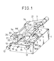
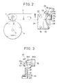
- Fig. 1 is a perspective view of a lens grinder including a device for maintaining abutting pressure against a grinder according to the present invention, in which identical or similar parts of Fig. 8 are denoted by identical reference numerals and description thereof is omitted. Also, the measurement of a peripheral edge position of a lens is performed in the same manner as described in Japanese patent application No. Sho 62-335672 filed by the present applicant.
- a body 1 of the apparatus is provided with a guide shaft 19 extending in a direction parallel with a drive shaft 2 (rotating shaft) of a V-edging grinder 4 and mounted to position (not shown) of a rear portion of the body 1.
- a carriage base 20 is reciprocally and movably held by the guide shaft 19 in the longitudinally direction thereof.
- the carriage base 20 is connected with an arm plate 15 and is reciprocally moved in the axial direction of the guide shaft 19 by a pulse motor 12 together with the arm plate 15.
- the carriage base 20 is provided at both ends in its moving direction with supporting portions 21,21 projecting upward therefrom.
- the carriage 7 is provided with an abutting force adjusting means 23 mounted on a rear end portion 7a thereof.
- the abutting force adjusting means 23 includes a pulse motor 24 mounted on the rear end portion 7a, a reduction gear 24a interlocked with the pulse motor 24, a rotating shaft 24b interlocked with the reduction gear 24a, a circular timing plate 25 and a lever 26 mounted on the rotating shaft 24b, and a microswitch 27 mounted on the rear end portion 7a.
- the timing plate 25 is formed with a V-shaped notch 25a.
- a roller 27b attached to an actuator lever 27a of the microswitch 27 is abutted against the peripheral surface of the timing plate 25. And, upon engagement of the roller 27b with the notch 25a, the microswitch 26 is switched off.
- a spring 28 is interposed between the free end portion or lower end portion of the lever 26 and the carriage base 20, a spring 28 is interposed.
- the timing plate 25 and the microswitch 27 constitute means for detecting a pivot starting position of the lever 26.
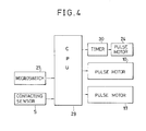
- the abutting force adjusting means 23 is drive controlled by CPU 29 (central processing unit) as a calculation control circuit (control circuit).
- CPU 29 central processing unit
- power output from the microswitch 26 and a signal from the contacting sensor S are input.
- the CPU 29 controls the rotating time of the pulse motor 24 through a timer 30.
- the CPU 29 calculates the rotation angle of the lens shafts 8,9 in accordance with a drive control pulse signal of the pulse motor 10 during rough grinding treatment of the lens and stores the same therein. An electric power is fed to the pulse motor 24 through the timer 30 when the timer 30 is being activated.
- the CPU 29 employs a measuring device as disclosed in the above-mentioned Japanese patent application in order to measure a positional coordinate of the peripheral edge of the roughly ground lens L in such a manner as that a radius vector ⁇ i of the lens L abutted against the V-edging grinder 4 is found in accordance with the shaft rotation angle of the lens shafts 8,9 and a swing angle ⁇ of the carriage 7, when the roughly ground lens L is abutted against the V-edging grinder 4 in this radius vector position, is calculated based on such obtained radius vector ⁇ i and a known carriage arm length.
- the CPU 29 determines the operating time of the timer 30 and the current feeding direction to the pulse motor 24, thereby to allow the timer 30 to control the current feeding time to the pulse motor 24 and the current feeding direction.
- the controlling of the current feeding time and the current feeding direction by the timer 30 is started from a position where the microswitch 27 is switched off due to engagement of the roller 27 with the notch 25a and is performed as such that a difference between a swing down moment by weight of the carriage acted on the abutting portion from the swing angle ⁇ of the carriage 7 and a pivot down preventing moment by the spring 28 becomes constant.
- the driving time of the pulse motor 24 is determined by the operating time of the timer 30, it may be designed as such that the number of drive pulse of the pulse motor 24 is found through the above calculation and such found number of drive pulse is input into the pulse motor 24 from the CPU 29 so as to drive control the pulse motor 24 directly by the CPU 29.
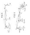
- Fig. 5 shows a case where the carriage 7 is in its horizontal position and where the swing angle thereof is zero.
- the lens grinding radius vector is denoted by ⁇ 0
- the correlation of A ⁇ W0, C ⁇ G0 and B ⁇ F0 becomes as follows;
- a ⁇ W0 + C ⁇ G0 B ⁇ F0
- the pulse motor is controlled as such that the lever is brought to its downwardly vertical position.
- Fig. 6 shows a case where the radius vector ⁇ i is ⁇ 1 which is larger than ⁇ 0.
- the radius vector ⁇ i is ⁇ 1 which is larger than ⁇ 0.
- Fig. 7 shows a case where the grinding radius vector ⁇ 1 is ⁇ 2 which is smaller than ⁇ 0.
- the force relation is arranged as follows; In this case, therefore, the lever is pivoted toward the side approaching to the swing center O.
- a swing angle detecting rotary encoder RE may be provided as shown by the broken line of Fig. 1.
- the present invention is not necessarily limited to this.
- a spring mounting member is movably mounted on the rear end portion 7a of the carriage 7 in such a manner as to move forward and backward with respect to the front end portion of the carriage 7, so that the upper end portion of the spring 28 is held by the spring mounting member and the spring mounting member is controlled by a pulse motor, a cylinder or the like in such a manner as to move forward and backward with respect to the front end portion of the carriage 7.
- a lens grinding apparatus including a V-edging grinder rotatably mounted on a body of the apparatus, a carriage swingably supported by a supporting shaft parallel with a rotating shaft of the V-edging grinder in such a manner as to be swung about the supporting shaft and adapted to hold a lens to be ground with a lens rotating shaft thereof, and means for measuring the radius vector of the lens
- the lens grinding apparatus comprises a carriage base having the supporting shaft and reciprocally movably mounted on the body in such a manner as to be moved in a direction parallel with the rotating shaft, a resilient member mounted at one end thereof on either a rear end portion of the carriage or the carriage base, abutting force adjusting means interposed between the rear end portion of the carriage or the carriage base, on which the resilient member is not mounted, and the other end of the resilient member, and control means for calculating a swing down moment of the carriage with reference to a swing angle of the carriage about the supporting shaft when the lens, which was
- the abutting force of the peripheral edge of the roughly ground lens against the V-edging grinder can be made smaller enough than the grinding pressure during the lens grinding treatment.
- this controlling may be utilized not only in a case where the peripheral edge is abutted and measured but also in a case where the grinding pressure during the lens grinding treatment is adjusted.
- the present invention employs a method for changing the position of the operating point of a spring, the adjusting device becomes small and easy to handle. Furthermore, it is of energy saving type.
- the adjusting range of the carriage pivot preventing moment can be taken large and one adjusting mechanism can be used both for adjusting the abutting force during the measurement of the thickness of the peripheral edge of a lens and for adjusting the grinding pressure during the grinding treatment of a lens.
Landscapes
- Engineering & Computer Science (AREA)
- Chemical & Material Sciences (AREA)
- Ceramic Engineering (AREA)
- Inorganic Chemistry (AREA)
- Mechanical Engineering (AREA)
- Grinding And Polishing Of Tertiary Curved Surfaces And Surfaces With Complex Shapes (AREA)
Applications Claiming Priority (2)
| Application Number | Priority Date | Filing Date | Title |
|---|---|---|---|
| JP64835/88 | 1988-03-18 | ||
| JP6483588A JPH0796185B2 (ja) | 1988-03-18 | 1988-03-18 | 玉摺機砥石へのレンズ定圧当接装置 |
Publications (3)
| Publication Number | Publication Date |
|---|---|
| EP0333598A2 true EP0333598A2 (fr) | 1989-09-20 |
| EP0333598A3 EP0333598A3 (en) | 1990-12-27 |
| EP0333598B1 EP0333598B1 (fr) | 1993-07-28 |
Family
ID=13269702
Family Applications (1)
| Application Number | Title | Priority Date | Filing Date |
|---|---|---|---|
| EP19890400760 Expired - Lifetime EP0333598B1 (fr) | 1988-03-18 | 1989-03-17 | Dispositif de meulage de lentilles |
Country Status (3)
| Country | Link |
|---|---|
| EP (1) | EP0333598B1 (fr) |
| JP (1) | JPH0796185B2 (fr) |
| DE (1) | DE68907757T2 (fr) |
Cited By (2)
| Publication number | Priority date | Publication date | Assignee | Title |
|---|---|---|---|---|
| EP0803325A3 (fr) * | 1996-04-25 | 1998-01-14 | Wernicke & Co. GmbH | Procédé pour le meulage façonné du bord de circonférence de verres de lunettes et le cas échéant meulage de facette suivant ainsi que dispositif de meulage pour les bords de verres de lunettes |
| CN116944962A (zh) * | 2023-09-08 | 2023-10-27 | 杭州电子科技大学浦江微电子与智能制造研究院有限公司 | 一种基于力位融合的水晶加工方法及装置 |
Family Cites Families (3)
| Publication number | Priority date | Publication date | Assignee | Title |
|---|---|---|---|---|
| DE1962821A1 (de) * | 1969-12-15 | 1971-06-16 | Textron Inc | Vorrichtung zum Zurichten von aufgebockten Linsenrohlingen |
| JPS6049545B2 (ja) * | 1982-04-16 | 1985-11-02 | 株式会社工研 | レンズ加工機 |
| JPS60123259A (ja) * | 1983-12-02 | 1985-07-01 | Nippon Kogaku Kk <Nikon> | レンズ周縁加工機 |
-
1988
- 1988-03-18 JP JP6483588A patent/JPH0796185B2/ja not_active Expired - Fee Related
-
1989
- 1989-03-17 EP EP19890400760 patent/EP0333598B1/fr not_active Expired - Lifetime
- 1989-03-17 DE DE1989607757 patent/DE68907757T2/de not_active Expired - Fee Related
Cited By (2)
| Publication number | Priority date | Publication date | Assignee | Title |
|---|---|---|---|---|
| EP0803325A3 (fr) * | 1996-04-25 | 1998-01-14 | Wernicke & Co. GmbH | Procédé pour le meulage façonné du bord de circonférence de verres de lunettes et le cas échéant meulage de facette suivant ainsi que dispositif de meulage pour les bords de verres de lunettes |
| CN116944962A (zh) * | 2023-09-08 | 2023-10-27 | 杭州电子科技大学浦江微电子与智能制造研究院有限公司 | 一种基于力位融合的水晶加工方法及装置 |
Also Published As
| Publication number | Publication date |
|---|---|
| EP0333598B1 (fr) | 1993-07-28 |
| DE68907757D1 (de) | 1993-09-02 |
| JPH0796185B2 (ja) | 1995-10-18 |
| EP0333598A3 (en) | 1990-12-27 |
| JPH01252349A (ja) | 1989-10-09 |
| DE68907757T2 (de) | 1994-02-24 |
Similar Documents
| Publication | Publication Date | Title |
|---|---|---|
| JP3992853B2 (ja) | 表面追従型測定機 | |
| JP5485676B2 (ja) | 表面性状測定機 | |
| GB2169408A (en) | Height gauge | |
| US6728656B2 (en) | Lens frame shape measuring apparatus | |
| JPH01295713A (ja) | ねじ軸有効径のインプロセス測定方法および装置 | |
| EP0333598A2 (fr) | Dispositif de meulage de lentilles | |
| US6261150B1 (en) | Eyeglass lens grinding apparatus | |
| US5317972A (en) | Offset printing machine, printing plate and image position reading-out method for offset printing machine | |
| JPH0569318A (ja) | 板状材の面取り方法及びその装置 | |
| GB1594005A (en) | Mounting for rotary cylinders particularly in a printing press | |
| JPS6130371A (ja) | ガラス板の縁端研削装置 | |
| US4020598A (en) | Method of measuring the radius of a rotating grinding wheel and device therefor | |
| CN116352513B (zh) | 电极修磨方法、修磨装置及焊接设备 | |
| JP2540095Y2 (ja) | クランクシャフトの振れ測定装置 | |
| JPH04201170A (ja) | 長尺軸の外面研削装置 | |
| JPH0655219A (ja) | ベンダーのクラウニング装置 | |
| JP2996898B2 (ja) | 帯状刃材の曲げ加工装置 | |
| JP3528291B2 (ja) | オンラインロール研削装置 | |
| CN216179640U (zh) | 一种用于磨削触点的磨削机 | |
| CN111761486B (zh) | 玻璃除膜装置自动调整方法 | |
| JP2579314Y2 (ja) | シート状部材の厚み測定装置 | |
| JPS61155901A (ja) | 触針式測定機 | |
| JPH07186025A (ja) | レンズ面取装置 | |
| JPH0799329B2 (ja) | 眼鏡レンズ枠又は型板形状測定装置 | |
| JP2806971B2 (ja) | レンズ研削装置 |
Legal Events
| Date | Code | Title | Description |
|---|---|---|---|
| PUAI | Public reference made under article 153(3) epc to a published international application that has entered the european phase |
Free format text: ORIGINAL CODE: 0009012 |
|
| AK | Designated contracting states |
Kind code of ref document: A2 Designated state(s): DE FR GB IT NL |
|
| PUAL | Search report despatched |
Free format text: ORIGINAL CODE: 0009013 |
|
| AK | Designated contracting states |
Kind code of ref document: A3 Designated state(s): DE FR GB IT NL |
|
| 17P | Request for examination filed |
Effective date: 19910202 |
|
| 17Q | First examination report despatched |
Effective date: 19920513 |
|
| GRAA | (expected) grant |
Free format text: ORIGINAL CODE: 0009210 |
|
| AK | Designated contracting states |
Kind code of ref document: B1 Designated state(s): DE FR GB IT NL |
|
| ITF | It: translation for a ep patent filed | ||
| REF | Corresponds to: |
Ref document number: 68907757 Country of ref document: DE Date of ref document: 19930902 |
|
| ET | Fr: translation filed | ||
| PLBE | No opposition filed within time limit |
Free format text: ORIGINAL CODE: 0009261 |
|
| STAA | Information on the status of an ep patent application or granted ep patent |
Free format text: STATUS: NO OPPOSITION FILED WITHIN TIME LIMIT |
|
| 26N | No opposition filed | ||
| REG | Reference to a national code |
Ref country code: GB Ref legal event code: IF02 |
|
| PGFP | Annual fee paid to national office [announced via postgrant information from national office to epo] |
Ref country code: NL Payment date: 20050228 Year of fee payment: 17 |
|
| PGFP | Annual fee paid to national office [announced via postgrant information from national office to epo] |
Ref country code: GB Payment date: 20050310 Year of fee payment: 17 |
|
| PGFP | Annual fee paid to national office [announced via postgrant information from national office to epo] |
Ref country code: FR Payment date: 20050325 Year of fee payment: 17 |
|
| PGFP | Annual fee paid to national office [announced via postgrant information from national office to epo] |
Ref country code: DE Payment date: 20050331 Year of fee payment: 17 |
|
| PG25 | Lapsed in a contracting state [announced via postgrant information from national office to epo] |
Ref country code: GB Free format text: LAPSE BECAUSE OF NON-PAYMENT OF DUE FEES Effective date: 20060317 |
|
| PGFP | Annual fee paid to national office [announced via postgrant information from national office to epo] |
Ref country code: IT Payment date: 20060331 Year of fee payment: 18 |
|
| PG25 | Lapsed in a contracting state [announced via postgrant information from national office to epo] |
Ref country code: NL Free format text: LAPSE BECAUSE OF NON-PAYMENT OF DUE FEES Effective date: 20061001 |
|
| PG25 | Lapsed in a contracting state [announced via postgrant information from national office to epo] |
Ref country code: DE Free format text: LAPSE BECAUSE OF NON-PAYMENT OF DUE FEES Effective date: 20061003 |
|
| GBPC | Gb: european patent ceased through non-payment of renewal fee |
Effective date: 20060317 |
|
| NLV4 | Nl: lapsed or anulled due to non-payment of the annual fee |
Effective date: 20061001 |
|
| REG | Reference to a national code |
Ref country code: FR Ref legal event code: ST Effective date: 20061130 |
|
| PG25 | Lapsed in a contracting state [announced via postgrant information from national office to epo] |
Ref country code: FR Free format text: LAPSE BECAUSE OF NON-PAYMENT OF DUE FEES Effective date: 20060331 |
|
| PG25 | Lapsed in a contracting state [announced via postgrant information from national office to epo] |
Ref country code: IT Free format text: LAPSE BECAUSE OF NON-PAYMENT OF DUE FEES Effective date: 20070317 |