EP0333566A1 - Verfahren und Anordnungen für die Verschiebung entlang der Frequenzachse des Moduls der Übertragungsfunktion eines Filters - Google Patents
Verfahren und Anordnungen für die Verschiebung entlang der Frequenzachse des Moduls der Übertragungsfunktion eines Filters Download PDFInfo
- Publication number
- EP0333566A1 EP0333566A1 EP89400675A EP89400675A EP0333566A1 EP 0333566 A1 EP0333566 A1 EP 0333566A1 EP 89400675 A EP89400675 A EP 89400675A EP 89400675 A EP89400675 A EP 89400675A EP 0333566 A1 EP0333566 A1 EP 0333566A1
- Authority
- EP
- European Patent Office
- Prior art keywords
- filter
- coefficients
- frequency
- transfer function
- module
- Prior art date
- Legal status (The legal status is an assumption and is not a legal conclusion. Google has not performed a legal analysis and makes no representation as to the accuracy of the status listed.)
- Granted
Links
- 238000012546 transfer Methods 0.000 title claims abstract description 27
- 238000000034 method Methods 0.000 title claims abstract description 13
- 238000013519 translation Methods 0.000 title description 3
- 230000006870 function Effects 0.000 claims description 25
- 230000015654 memory Effects 0.000 claims description 18
- 238000012545 processing Methods 0.000 claims description 8
- 238000002592 echocardiography Methods 0.000 abstract description 18
- 230000008030 elimination Effects 0.000 abstract description 2
- 238000003379 elimination reaction Methods 0.000 abstract description 2
- 238000010586 diagram Methods 0.000 description 10
- 238000001914 filtration Methods 0.000 description 5
- 238000001228 spectrum Methods 0.000 description 3
- 230000005540 biological transmission Effects 0.000 description 2
- 230000004044 response Effects 0.000 description 2
- 238000013459 approach Methods 0.000 description 1
- 230000001427 coherent effect Effects 0.000 description 1
- 230000000295 complement effect Effects 0.000 description 1
- 238000011161 development Methods 0.000 description 1
- 230000018109 developmental process Effects 0.000 description 1
- 230000000694 effects Effects 0.000 description 1
- 230000003071 parasitic effect Effects 0.000 description 1
- 230000010363 phase shift Effects 0.000 description 1
- 238000005070 sampling Methods 0.000 description 1
Images


Classifications
-
- G—PHYSICS
- G01—MEASURING; TESTING
- G01S—RADIO DIRECTION-FINDING; RADIO NAVIGATION; DETERMINING DISTANCE OR VELOCITY BY USE OF RADIO WAVES; LOCATING OR PRESENCE-DETECTING BY USE OF THE REFLECTION OR RERADIATION OF RADIO WAVES; ANALOGOUS ARRANGEMENTS USING OTHER WAVES
- G01S13/00—Systems using the reflection or reradiation of radio waves, e.g. radar systems; Analogous systems using reflection or reradiation of waves whose nature or wavelength is irrelevant or unspecified
- G01S13/02—Systems using reflection of radio waves, e.g. primary radar systems; Analogous systems
- G01S13/50—Systems of measurement based on relative movement of target
- G01S13/52—Discriminating between fixed and moving objects or between objects moving at different speeds
- G01S13/522—Discriminating between fixed and moving objects or between objects moving at different speeds using transmissions of interrupted pulse modulated waves
- G01S13/524—Discriminating between fixed and moving objects or between objects moving at different speeds using transmissions of interrupted pulse modulated waves based upon the phase or frequency shift resulting from movement of objects, with reference to the transmitted signals, e.g. coherent MTi
- G01S13/526—Discriminating between fixed and moving objects or between objects moving at different speeds using transmissions of interrupted pulse modulated waves based upon the phase or frequency shift resulting from movement of objects, with reference to the transmitted signals, e.g. coherent MTi performing filtering on the whole spectrum without loss of range information, e.g. using delay line cancellers or comb filters
-
- G—PHYSICS
- G01—MEASURING; TESTING
- G01S—RADIO DIRECTION-FINDING; RADIO NAVIGATION; DETERMINING DISTANCE OR VELOCITY BY USE OF RADIO WAVES; LOCATING OR PRESENCE-DETECTING BY USE OF THE REFLECTION OR RERADIATION OF RADIO WAVES; ANALOGOUS ARRANGEMENTS USING OTHER WAVES
- G01S13/00—Systems using the reflection or reradiation of radio waves, e.g. radar systems; Analogous systems using reflection or reradiation of waves whose nature or wavelength is irrelevant or unspecified
- G01S13/02—Systems using reflection of radio waves, e.g. primary radar systems; Analogous systems
- G01S13/50—Systems of measurement based on relative movement of target
- G01S13/52—Discriminating between fixed and moving objects or between objects moving at different speeds
- G01S13/522—Discriminating between fixed and moving objects or between objects moving at different speeds using transmissions of interrupted pulse modulated waves
- G01S13/524—Discriminating between fixed and moving objects or between objects moving at different speeds using transmissions of interrupted pulse modulated waves based upon the phase or frequency shift resulting from movement of objects, with reference to the transmitted signals, e.g. coherent MTi
- G01S13/5244—Adaptive clutter cancellation
-
- H—ELECTRICITY
- H03—ELECTRONIC CIRCUITRY
- H03H—IMPEDANCE NETWORKS, e.g. RESONANT CIRCUITS; RESONATORS
- H03H17/00—Networks using digital techniques
- H03H17/02—Frequency selective networks
- H03H17/06—Non-recursive filters
Definitions
- the invention relates to a method for shifting in frequency the module of the transfer function of a filter of the digital type and with transverse structure; it also relates to devices for implementing said method.
- Frequency filters of electrical signals are used in many fields of electronics and in particular in the processing of radar signals to eliminate for example fixed echoes or to detect echoes having determined characteristics such as a radial speed.
- This processing mode is for example used in coherent Doppler radars with constant ambiguous speed pulses which make it possible, by taking advantage of the Doppler effect, to detect mobile obstacles which give rise to radar signals of low amplitude in the middle of fixed obstacles corresponding to large amplitude radar signals. Indeed, in these pulse radars the waves received after reflection on the moving obstacles are affected by a phase which varies from one repetition period to the next while the waves received from the fixed obstacles do not exhibit such a variation in the phase shift. .
- the signals which correspond to fixed obstacles have a constant amplitude and their spectrum consists of a series of discrete lines at frequencies O, Fr 2Fr, ... nFr, Fr being the repetition frequency of the transmitted pulses.
- the spectrum of the signals corresponding to mobile obstacles is made up of discrete lines of the mFr - + Fd type.
- the filters are often made in digital form, that is to say that the signals to be filtered are sampled at a frequency equal to the repetition frequency of the pulses emitted by the radar, then the amplitude of the samples is coded so as to obtain a succession of digital codes; finally, these codes are multiplied by coefficients whose values define the characteristics of the filtering get.
- Such digital filters can be used in fields other than that of radars, for example in that of high-fidelity signals, in particular when such signals are in digital form. In these fields, there is also a need to modify the transfer function of the filters on the frequency axis without however profoundly modifying the structure of the filters, for example to extend the rejection band of the filter.
- An object of the present invention is therefore to implement a method which makes it possible, in a transverse filter, to shift in frequency the module of the transfer function of said filter.
- Another object of the invention is to provide devices for implementing the method which, for certain values of the frequency offset, are simple to carry out.
- This device comprises several delay lines, for example three, LR1 , LR2 and LR3 arranged in series, each delay line introducing a delay equal to the repetition period Tr of the pulses emitted at frequency Fr.
- Each delay line output and the input of the first LR1 are respectively connected to a circuit multiplication or weighting MO, M1, M2 and M3 in which the amplitude of the signal is multiplied or weighted respectively by a coefficient K0, K1, K2, and K3.
- the outputs of the multiplication circuits are connected to a summing circuit S which performs the sum of the weighted signals so as to obtain a filtered signal.
- the values of the coefficients K0, K1, K2 and K3 can be 1, -3, 3 and -1 respectively and the frequency transfer function of such a filter is of the form
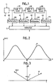
- the module of the frequency response curve of such a filter is given by the diagram in FIG. 2.
- such a filter is known as a transverse filter and is of the type with cancellation on four pulses. , which corresponds to the Anglo-Saxon expression of "four-pulse canceler transverse filter".
- the samples X i to X i + 3 therefore correspond to a radar signal coming from a distance box located at a determined distance from the antenna of the radar equal to t / C if C is the speed of light.
- FIG. 3 makes it possible to understand the approach of the invention.
- such a multiplication circuit 10 is no longer necessary and is replaced by new values K′0, K′1, K′2, and K′3 of the multiplication coefficients used in the circuits M0 to M3, values which are fixed and which, for certain values of the frequency Fd, are easy to perform digitally.
- the z-transform of a discrete-time signal (x n ) is defined by the series:
- x n corresponds to the series of samples separated from each other by a repetition period Tr.
- FIG. 4 gives the canonical structure of such a transverse filter in the case of a weighting made on four pulses.
- the input of the operator circuit Z1 as well as the outputs of the operator circuits Z1, Z2 and Z3 are connected to multiplier circuits M′0 to M′3 which carry out the multiplication by the coefficients K′0 to K′3 respectively.
- Hi (z) and H ′ (z) have the same module, which means that we perform the same filtering with structure (C) as with structure (B) if we do not s 'is only of interest in the module, but in structure (C) the coefficients no longer depend on the rank of the sample in the repetition period and are therefore fixed values.
- the four coefficients K′0 to K′3 can be respectively equal to one of the following four groups - (-d, 3, 3d, -1) - (1, 3d, -3, -d) - (d, -3, -3d, 1) - (-1, -3d, 3, j)
- they can be respectively equal to: - (j, 3, -3d, -1) - (1, -3d, -3, j) - (-j, -3, 3d, 1) - (-1, 3d, 3, -d)
- the modulus of the frequency transfer function H ′ (f) is given by curve 12 in FIG. 5 which corresponds to curve 11 elimination of fixed echoes in Figure 2, but moved by -Fr / 4 on the frequency axis.
- Such a transfer function, the transmission maximum of which is at + Fr / 4 makes it possible to eliminate the echoes corresponding to the Doppler frequencies close to -Fr / 4.
- the modulus of the frequency transfer function H ′ (f) is given by curve 13 in FIG. 6 which corresponds to curve 11 for eliminating fixed echoes but displaced by + Fr / 4 over l 'frequency axis.
- Such a transfer function whose maximum transmission is at -Fr / 4 allows the filter to eliminate the echoes corresponding to the Doppler frequencies close to + Fr / 4.
- FIG. 7 is a diagram of a digital filtering device which implements the method of the invention in the case of simultaneous frequency offsets of + Fr / 4 and -Fr / 4 with processing on four pulses at using three memories each carrying a delay line.
- the signal to be filtered is presented in the form of its two real components I and imaginary Q which are first processed in two separate channels and then in a common part.
- Each separate channel comprises a memory 20 (or 21) which is made up, in the case of simultaneous processing on four samples, of three identical elementary memories 22, 24, 26 (or 23, 25, 27) which are provided for recording each, in the case of a radar signal, the sample codes corresponding to a repetition period Tr.
- the outputs of memories 22 and 24 (or 23 and 25) are connected respectively to adder circuits 28 and 30 (or 29 and 31) which carry out the operation multiplication by the coefficient 3.
- the common part includes adder circuits 32 to 39 and two module calculation circuits.
- the adder circuits 32 to 35 and 36, 39 have a direct input + and a complementary input - which completes the code applied to it. More precisely, the inputs (-) of the adder circuits 32 to 35 are connected respectively: - at the output of memory 26, - at the output of the adder circuit 31, - at the input of memory 22, and - at the output of memory 27.
- the outputs (+) of the adder circuits 32 to 35 are connected respectively: - at the output of the adder circuit 28, - at the input of memory 23, - at the output of the adder circuit 30, and - at the output of the adder circuit 29.
- Each output of the adding circuits 32 to 35 is connected to one of the two inputs of one of the adding circuits 36 to 39.
- the output of the adding circuit 32 is connected to the inputs (+) of the adding circuits 36 and 37;
- the output of the adder circuit 33 is connected to the input (-) of the circuit 36 and to the input (+) of the circuit 37;
- the output of circuit 34 is connected to the input (+) of circuit 38 and to the input (-) of circuit 31;
- the output of circuit 35 is connected to the input (+) of circuits 38 and 39.
- the outputs 42 and 45 of circuits 36 and 39 are connected to the two inputs of the module calculation circuit 41 while the outputs 43 and 44 are connected to the two inputs of the module calculation circuit 40.
- the respective coefficients which have been indicated above are -1, -3j, 3 and j, for the complex samples X3, X2, X1, XO.
- -1 (I3 + jQ3) - 3j (I2 + jQ2) + 3 (I1 + JQ1) + j (Io + JQo) either: - I3 + 3I1 - QO + 3Q2 + j (-Q3 + 3Q1 + IO - 3I2) , which corresponds for the real part to the output 42 of the circuit 36 and for the imaginary part to the output 45 of circuit 39.
- the circuit for calculating the module 40 therefore gives the module of the signal corresponding to the filter + Fr / 4 while the circuit 41 gives the module of the signal corresponding to the filter -Fr / 4.
- the description which has just been given in relation to FIG. 7 shows that the application of the invention to particular cases of filters makes it possible to achieve simple digital devices, easy to produce and using only elementary circuits .
- the invention has been described in relation to a particular application in the field of radars. However, it is understood that the invention applies to the filtering of all types of electrical signals provided that they are sampled at a frequency at least equal to twice the maximum frequency of the useful spectrum so as to obtain the samples Xi separated by intervals of times equal to the sampling period.
- each transverse filter having an appropriate transfer function so that the sum transfer functions lead to the global transfer function sought.
Landscapes
- Engineering & Computer Science (AREA)
- Radar, Positioning & Navigation (AREA)
- Remote Sensing (AREA)
- Physics & Mathematics (AREA)
- Computer Networks & Wireless Communication (AREA)
- General Physics & Mathematics (AREA)
- Computer Hardware Design (AREA)
- Mathematical Physics (AREA)
- Radar Systems Or Details Thereof (AREA)
Applications Claiming Priority (2)
| Application Number | Priority Date | Filing Date | Title |
|---|---|---|---|
| FR8803524 | 1988-03-18 | ||
| FR8803524A FR2628909B1 (fr) | 1988-03-18 | 1988-03-18 | Procede et dispositifs de translation le long de l'axe des frequences du module de la fonction de transfert d'un filtre |
Publications (2)
| Publication Number | Publication Date |
|---|---|
| EP0333566A1 true EP0333566A1 (de) | 1989-09-20 |
| EP0333566B1 EP0333566B1 (de) | 1992-09-23 |
Family
ID=9364391
Family Applications (1)
| Application Number | Title | Priority Date | Filing Date |
|---|---|---|---|
| EP89400675A Expired - Lifetime EP0333566B1 (de) | 1988-03-18 | 1989-03-10 | Verfahren und Anordnungen für die Verschiebung entlang der Frequenzachse des Moduls der Übertragungsfunktion eines Filters |
Country Status (4)
| Country | Link |
|---|---|
| US (1) | US4965584A (de) |
| EP (1) | EP0333566B1 (de) |
| DE (1) | DE68902937T2 (de) |
| FR (1) | FR2628909B1 (de) |
Families Citing this family (2)
| Publication number | Priority date | Publication date | Assignee | Title |
|---|---|---|---|---|
| DE4013684C2 (de) * | 1990-04-28 | 1994-04-07 | Honeywell Elac Nautik Gmbh | Verfahren und Schaltungsanordnung zum Erkennen störungsbehafteter Signale |
| DE10115607A1 (de) * | 2001-03-29 | 2002-10-02 | Valeo Schalter & Sensoren Gmbh | Verfahren und Vorrichtung zur Detektion von Objekten in Entfernungszellen mittels Radarsignalen |
Citations (2)
| Publication number | Priority date | Publication date | Assignee | Title |
|---|---|---|---|---|
| US4463356A (en) * | 1981-08-17 | 1984-07-31 | Sperry Corporation | Apparatus for control of clutter breakthrough in MTI radar |
| GB2173366A (en) * | 1985-04-05 | 1986-10-08 | Grass Valley Group | A mixer controlled variable passband finite impulse response filter |
Family Cites Families (13)
| Publication number | Priority date | Publication date | Assignee | Title |
|---|---|---|---|---|
| US3877010A (en) * | 1967-10-26 | 1975-04-08 | Hughes Aircraft Co | Adaptable moving target processor |
| US4035799A (en) * | 1975-11-04 | 1977-07-12 | The United States Of America As Represented By The Secretary Of The Navy | Digital mean clutter doppler compensation system |
| US4153899A (en) * | 1976-03-10 | 1979-05-08 | Westinghouse Electric Corp. | MTI radar system and method |
| JPS5348496A (en) * | 1976-10-14 | 1978-05-01 | Mitsubishi Electric Corp | Moving target displaying system |
| US4173017A (en) * | 1977-04-11 | 1979-10-30 | The United States Of America As Represented By The Secretary Of The Army | Programmable signal processor for Doppler filtering |
| US4137532A (en) * | 1977-04-29 | 1979-01-30 | Westinghouse Electric Corp. | VIP doppler filter bank signal processor for pulse doppler radar |
| JPS5964912A (ja) * | 1982-10-05 | 1984-04-13 | Nec Corp | デイジタルフイルタ |
| JPS6024477A (ja) * | 1983-07-21 | 1985-02-07 | Nec Corp | レ−ダ−信号処理装置 |
| US4616229A (en) * | 1983-09-30 | 1986-10-07 | Westinghouse Electric Corp. | System and method of compensating a doppler processor for input unbalance and an unbalance measuring sensor for use therein |
| US4694298A (en) * | 1983-11-04 | 1987-09-15 | Itt Gilfillan | Adaptive, fault-tolerant narrowband filterbank |
| US4709236A (en) * | 1985-05-08 | 1987-11-24 | Westinghouse Electric Corp. | Selectable doppler filter for radar systems |
| EP0227457B1 (de) * | 1985-12-23 | 1993-09-15 | Nec Corporation | Radarsystem |
| US4783660A (en) * | 1986-09-29 | 1988-11-08 | Signatron, Inc. | Signal source distortion compensator |
-
1988
- 1988-03-18 FR FR8803524A patent/FR2628909B1/fr not_active Expired - Lifetime
-
1989
- 1989-03-10 DE DE8989400675T patent/DE68902937T2/de not_active Expired - Fee Related
- 1989-03-10 EP EP89400675A patent/EP0333566B1/de not_active Expired - Lifetime
- 1989-03-20 US US07/325,586 patent/US4965584A/en not_active Expired - Fee Related
Patent Citations (2)
| Publication number | Priority date | Publication date | Assignee | Title |
|---|---|---|---|---|
| US4463356A (en) * | 1981-08-17 | 1984-07-31 | Sperry Corporation | Apparatus for control of clutter breakthrough in MTI radar |
| GB2173366A (en) * | 1985-04-05 | 1986-10-08 | Grass Valley Group | A mixer controlled variable passband finite impulse response filter |
Non-Patent Citations (3)
| Title |
|---|
| IEEE TRANSACTIONS ON AUDIO AND ELECTROACOUSTICS, vol. AU-19, no. 1, mars 1971, pages 72-77; W. ROECKER: "The application of digital filters for moving target indication" * |
| PATENT ABSTRACTS OF JAPAN, vol. 2, no. 84, 8 juillet 1978, page 3606 E 78; & JP-A-53 48 496 (MITSUBISHI DENKI K.K.) 01-05-1978 * |
| RCA REVIEW, vol. 32, no. 3, septembre 1971, pages 402-428; T. MURAKAMI et al.: "Clutter suppression by use of weighted pulse trains" * |
Also Published As
| Publication number | Publication date |
|---|---|
| US4965584A (en) | 1990-10-23 |
| EP0333566B1 (de) | 1992-09-23 |
| DE68902937T2 (de) | 1993-02-25 |
| DE68902937D1 (de) | 1992-10-29 |
| FR2628909B1 (fr) | 1990-07-13 |
| FR2628909A1 (fr) | 1989-09-22 |
Similar Documents
| Publication | Publication Date | Title |
|---|---|---|
| EP0036348B1 (de) | Aktives Detektionssystem mit gleichzeitiger Ausstrahlung von Frequenzimpulsen | |
| EP0932836B1 (de) | Verfahren für impulskompression mit synthetischem-band wellenformen | |
| EP0877260A1 (de) | Verfahren zum Bearbeiten von Emfpangssignalen aus einem SAR-Radar mit Frequenz-Rampen | |
| FR2587819A1 (fr) | Dispositif de calcul d'une transformee de fourier discrete, glissante et non recursive, et son application a un systeme radar | |
| EP0884605A1 (de) | Verfahren zur Verarbeitung eines empfangenen Signals einer Radaranlage mit synthetischer Apertur vom FDERAMP-Typ | |
| CA1263756A (fr) | Dispositif de calcul d'une transformee de fourier discrete et son application a la compression d'impulsion dans un systeme radar | |
| EP0068909B1 (de) | Verfahren und Vorrichtung zur Verminderung der über die Nebenzipfel einer Radarantenne empfangenen Störsignalstärke | |
| EP0334711B1 (de) | Gerät zur Unterdrückung von beweglichen Störechos in einem Radar | |
| EP0207859A1 (de) | Rechnungseinrichtung zur diskreten und verschiebenden Fourier-Transformation zur Verwendung in einem Radarsystem | |
| EP0493189B1 (de) | Digitalkodierte Impulssignalverarbeitung | |
| FR2652654A1 (fr) | Echographe ultrasonore utilisant un dispositif numerique de formation de voies en reception. | |
| EP3671250B1 (de) | Digitales interferometer mit unterabtastung | |
| EP0147305B1 (de) | Anordnung zur Unterscheidung von Radarechos | |
| EP0333566B1 (de) | Verfahren und Anordnungen für die Verschiebung entlang der Frequenzachse des Moduls der Übertragungsfunktion eines Filters | |
| EP0464115A1 (de) | Verfahren und anordnung zur spektralanalyse in realzeit von komplexen instationären signalen | |
| EP1940023A2 (de) | Kaskadierbare, digitale Filterbank und darin enthaltene Empfangsschaltung | |
| FR2632420A1 (fr) | Procede et dispositif de compensation de la vitesse du fouillis dans un radar doppler coherent a vitesse ambigue variable | |
| FR2629602A1 (fr) | Dispositif de traitement des signaux d'un radar a vision laterale, et systeme radar comportant un tel dispositif | |
| EP0010481B1 (de) | Verfahren und Vorrichtung zum Anzeigen bewegender Ziele, insbesondere bei einem Radargerät mit variabler Wiederholungsfrequenz | |
| EP1326091B1 (de) | Verfahren zur Verbesserung der Qualität eines Radarbildes | |
| CA1190614A (fr) | Systeme de filtration adaptif destine a annuler un ou plusieurs signaux d'interference de forme sinusoidale | |
| EP0029760B1 (de) | Filtervorrichtung und ihre Verwendung bei Radaranzeigesystemen | |
| FR2724028A1 (fr) | Procede d'estimation aveugle de retards differentiels entre deux signaux | |
| FR2739453A1 (fr) | Procede et dispositif d'elimination adaptative de fouillis dans un radar doppler a impulsions | |
| FR2680250A1 (fr) | Procede et dispositif d'imagerie ultra-sonore d'objets en milieu liquide. |
Legal Events
| Date | Code | Title | Description |
|---|---|---|---|
| PUAI | Public reference made under article 153(3) epc to a published international application that has entered the european phase |
Free format text: ORIGINAL CODE: 0009012 |
|
| AK | Designated contracting states |
Kind code of ref document: A1 Designated state(s): DE GB IT NL |
|
| 17P | Request for examination filed |
Effective date: 19900131 |
|
| 17Q | First examination report despatched |
Effective date: 19920303 |
|
| GRAA | (expected) grant |
Free format text: ORIGINAL CODE: 0009210 |
|
| AK | Designated contracting states |
Kind code of ref document: B1 Designated state(s): DE GB IT NL |
|
| PG25 | Lapsed in a contracting state [announced via postgrant information from national office to epo] |
Ref country code: NL Effective date: 19920923 |
|
| ITF | It: translation for a ep patent filed | ||
| REF | Corresponds to: |
Ref document number: 68902937 Country of ref document: DE Date of ref document: 19921029 |
|
| GBT | Gb: translation of ep patent filed (gb section 77(6)(a)/1977) | ||
| PGFP | Annual fee paid to national office [announced via postgrant information from national office to epo] |
Ref country code: GB Payment date: 19930225 Year of fee payment: 5 Ref country code: DE Payment date: 19930225 Year of fee payment: 5 |
|
| NLV1 | Nl: lapsed or annulled due to failure to fulfill the requirements of art. 29p and 29m of the patents act | ||
| PLBI | Opposition filed |
Free format text: ORIGINAL CODE: 0009260 |
|
| 26 | Opposition filed |
Opponent name: ANT NACHRICHTENTECHNIK GMBH PATENTABTEILUNG Effective date: 19930619 |
|
| RAP2 | Party data changed (patent owner data changed or rights of a patent transferred) |
Owner name: THOMSON-CSF |
|
| PG25 | Lapsed in a contracting state [announced via postgrant information from national office to epo] |
Ref country code: GB Effective date: 19940310 |
|
| GBPC | Gb: european patent ceased through non-payment of renewal fee |
Effective date: 19940310 |
|
| PG25 | Lapsed in a contracting state [announced via postgrant information from national office to epo] |
Ref country code: DE Effective date: 19941201 |
|
| PLBO | Opposition rejected |
Free format text: ORIGINAL CODE: EPIDOS REJO |
|
| PLBN | Opposition rejected |
Free format text: ORIGINAL CODE: 0009273 |
|
| STAA | Information on the status of an ep patent application or granted ep patent |
Free format text: STATUS: OPPOSITION REJECTED |
|
| 27O | Opposition rejected |
Effective date: 19980410 |
|
| PG25 | Lapsed in a contracting state [announced via postgrant information from national office to epo] |
Ref country code: IT Free format text: LAPSE BECAUSE OF NON-PAYMENT OF DUE FEES;WARNING: LAPSES OF ITALIAN PATENTS WITH EFFECTIVE DATE BEFORE 2007 MAY HAVE OCCURRED AT ANY TIME BEFORE 2007. THE CORRECT EFFECTIVE DATE MAY BE DIFFERENT FROM THE ONE RECORDED. Effective date: 20050310 |