EP0010481B1 - Verfahren und Vorrichtung zum Anzeigen bewegender Ziele, insbesondere bei einem Radargerät mit variabler Wiederholungsfrequenz - Google Patents
Verfahren und Vorrichtung zum Anzeigen bewegender Ziele, insbesondere bei einem Radargerät mit variabler Wiederholungsfrequenz Download PDFInfo
- Publication number
- EP0010481B1 EP0010481B1 EP79400713A EP79400713A EP0010481B1 EP 0010481 B1 EP0010481 B1 EP 0010481B1 EP 79400713 A EP79400713 A EP 79400713A EP 79400713 A EP79400713 A EP 79400713A EP 0010481 B1 EP0010481 B1 EP 0010481B1
- Authority
- EP
- European Patent Office
- Prior art keywords
- ponderation
- signal
- signals
- phase
- channels
- Prior art date
- Legal status (The legal status is an assumption and is not a legal conclusion. Google has not performed a legal analysis and makes no representation as to the accuracy of the status listed.)
- Expired
Links
- 238000000034 method Methods 0.000 title claims description 10
- 238000001914 filtration Methods 0.000 claims description 9
- 230000014509 gene expression Effects 0.000 claims description 7
- 238000012800 visualization Methods 0.000 claims description 5
- 230000005540 biological transmission Effects 0.000 claims description 3
- 238000001228 spectrum Methods 0.000 claims description 2
- 238000004132 cross linking Methods 0.000 claims 3
- 238000012986 modification Methods 0.000 claims 1
- 230000004048 modification Effects 0.000 claims 1
- 238000002592 echocardiography Methods 0.000 description 9
- 230000006870 function Effects 0.000 description 3
- 230000000712 assembly Effects 0.000 description 2
- 238000000429 assembly Methods 0.000 description 2
- 230000001427 coherent effect Effects 0.000 description 2
- 230000003111 delayed effect Effects 0.000 description 2
- 238000001514 detection method Methods 0.000 description 2
- 238000010586 diagram Methods 0.000 description 2
- 235000008694 Humulus lupulus Nutrition 0.000 description 1
- 230000000694 effects Effects 0.000 description 1
- 230000008030 elimination Effects 0.000 description 1
- 238000003379 elimination reaction Methods 0.000 description 1
- 239000000463 material Substances 0.000 description 1
- 230000003071 parasitic effect Effects 0.000 description 1
- 238000012545 processing Methods 0.000 description 1
- 238000012552 review Methods 0.000 description 1
- 238000005070 sampling Methods 0.000 description 1
- 230000003595 spectral effect Effects 0.000 description 1
- 230000001629 suppression Effects 0.000 description 1
- 238000012546 transfer Methods 0.000 description 1
- 230000017105 transposition Effects 0.000 description 1
- 238000011144 upstream manufacturing Methods 0.000 description 1
Images
Classifications
-
- G—PHYSICS
- G01—MEASURING; TESTING
- G01S—RADIO DIRECTION-FINDING; RADIO NAVIGATION; DETERMINING DISTANCE OR VELOCITY BY USE OF RADIO WAVES; LOCATING OR PRESENCE-DETECTING BY USE OF THE REFLECTION OR RERADIATION OF RADIO WAVES; ANALOGOUS ARRANGEMENTS USING OTHER WAVES
- G01S13/00—Systems using the reflection or reradiation of radio waves, e.g. radar systems; Analogous systems using reflection or reradiation of waves whose nature or wavelength is irrelevant or unspecified
- G01S13/02—Systems using reflection of radio waves, e.g. primary radar systems; Analogous systems
- G01S13/06—Systems determining position data of a target
- G01S13/08—Systems for measuring distance only
- G01S13/10—Systems for measuring distance only using transmission of interrupted, pulse modulated waves
- G01S13/22—Systems for measuring distance only using transmission of interrupted, pulse modulated waves using irregular pulse repetition frequency
- G01S13/225—Systems for measuring distance only using transmission of interrupted, pulse modulated waves using irregular pulse repetition frequency with cyclic repetition of a non-uniform pulse sequence, e.g. staggered PRF
-
- G—PHYSICS
- G01—MEASURING; TESTING
- G01S—RADIO DIRECTION-FINDING; RADIO NAVIGATION; DETERMINING DISTANCE OR VELOCITY BY USE OF RADIO WAVES; LOCATING OR PRESENCE-DETECTING BY USE OF THE REFLECTION OR RERADIATION OF RADIO WAVES; ANALOGOUS ARRANGEMENTS USING OTHER WAVES
- G01S13/00—Systems using the reflection or reradiation of radio waves, e.g. radar systems; Analogous systems using reflection or reradiation of waves whose nature or wavelength is irrelevant or unspecified
- G01S13/02—Systems using reflection of radio waves, e.g. primary radar systems; Analogous systems
- G01S13/50—Systems of measurement based on relative movement of target
- G01S13/52—Discriminating between fixed and moving objects or between objects moving at different speeds
- G01S13/522—Discriminating between fixed and moving objects or between objects moving at different speeds using transmissions of interrupted pulse modulated waves
- G01S13/524—Discriminating between fixed and moving objects or between objects moving at different speeds using transmissions of interrupted pulse modulated waves based upon the phase or frequency shift resulting from movement of objects, with reference to the transmitted signals, e.g. coherent MTi
- G01S13/526—Discriminating between fixed and moving objects or between objects moving at different speeds using transmissions of interrupted pulse modulated waves based upon the phase or frequency shift resulting from movement of objects, with reference to the transmitted signals, e.g. coherent MTi performing filtering on the whole spectrum without loss of range information, e.g. using delay line cancellers or comb filters
- G01S13/528—Discriminating between fixed and moving objects or between objects moving at different speeds using transmissions of interrupted pulse modulated waves based upon the phase or frequency shift resulting from movement of objects, with reference to the transmitted signals, e.g. coherent MTi performing filtering on the whole spectrum without loss of range information, e.g. using delay line cancellers or comb filters with elimination of blind speeds
-
- G—PHYSICS
- G01—MEASURING; TESTING
- G01S—RADIO DIRECTION-FINDING; RADIO NAVIGATION; DETERMINING DISTANCE OR VELOCITY BY USE OF RADIO WAVES; LOCATING OR PRESENCE-DETECTING BY USE OF THE REFLECTION OR RERADIATION OF RADIO WAVES; ANALOGOUS ARRANGEMENTS USING OTHER WAVES
- G01S7/00—Details of systems according to groups G01S13/00, G01S15/00, G01S17/00
- G01S7/02—Details of systems according to groups G01S13/00, G01S15/00, G01S17/00 of systems according to group G01S13/00
- G01S7/28—Details of pulse systems
- G01S7/285—Receivers
- G01S7/292—Extracting wanted echo-signals
- G01S7/2923—Extracting wanted echo-signals based on data belonging to a number of consecutive radar periods
Definitions
- the present invention relates to the display of moving targets in radar equipment with a variable repetition period.
- the frequency of recurrence that is to say the duration of the repetition period, of the Doppler radar in question is varied by hops.
- the signals from two coherent detectors and phase shifted by jr / 2 relative to each other are preferably sampled in digital.
- the so-called sine channel and the so-called cosine channel two samples are taken, by echo, which are stored in memory so that samples corresponding to three successive recurrences can be placed simultaneously.
- the signals resulting from the difference between the three signals thus defined are then applied to a weighting device which comprises two multipliers with variable coefficients, these coefficients being a function of the recurrence considered.
- the signals leaving these weighting devices are added and then processed in a known manner in a filtering and detection device.
- the weighting operation is simplified by carrying out only one directly on the difference which is created at a given instant.
- the weighting operation is carried out with a real and / or complex coefficient, the weighting circuit delivering on its two output channels compensation signals obtained by linear combinations of the signals representing differences of the signals appearing in two successive recurrences delivered to the entry of the circuit by the sine and cosine channels.
- the useful video signal was taken into consideration as formed by a combination of the differences of the sampled signals with successive recurrences taken two by two and that a weighted sum of these differences was carried out with weighting coefficients varying over time as a function of the variation in the periods of recurrence.
- the weighted summation of the differences is no longer carried out, but only a single weighting is carried out on a single signal representing the difference obtained over two repetition periods successive.
- the weighting coefficient chosen which varies according to the values of the last repetition periods, can be either real or complex; in the case where the coefficient is complex, this amounts to operating on the vector representing the video signal considered, a homothety followed by a rotation so that the vector obtained at the output of the device implementing the invention is equipollent to the vector " ideal "which would be received at the input of the device for a frequency for which compensation is sought, in other words that the" corrected "vector would have the same amplitude and the same phase as this ideal vector. In the case where the weighting coefficient is real, the vector considered would undergo only one homothety.
- the device in which the weighting takes place is advantageously placed between two filtering devices canceling the zero frequency.
- the elimination of the zero Doppler frequency being carried out in the first of these filtering devices is therefore not disturbed by any imperfections in the weighting.
- the compensation remains effective for frequencies close to that chosen.
- the weighting device can be followed by a filtering device of any structure having a rejection zone which contains the frequency f on which the compensation system is adjusted.
- phase modulation coefficient is determined which must be applied to the signal Ui-1-Ui so that the signal obtained after weighting has a phase identical to that which the difference vector would have in the absence of variations in duration. recurrence periods.
- the expression of the phase of the phase modulation coefficient being we can determine the phase increment to apply to it from one period to another, either:
- the treated vector which in the general case has therefore undergone a homothetic operation followed by a rotation has become an equipollent vector to the vector applied to the input of the device which would correspond to a pure Doppler frequency.
- the signals obtained after weighting are then conventionally processed in filters, then rectified and applied for example to a display or operating device.
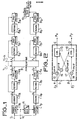
- FIG. 1 gives an exemplary embodiment of the device for displaying mobile targets according to the invention, in which only the part of the receiver of the Doppler radar concerned has been shown.
- the radar intermediate frequency receiver has an output S which is also the input of the device considered.
- This terminal S is connected to two demodulators la and 1b respectively which receive the signal leaving the intermediate frequency receiver, as well as a reference signal by the terminal R, reference signal which is phase shifted by x / 2 in the circuit 11 before to be applied to demodulator 1b.
- the signals coming out of the demodulators 1a and 1b thus constitute the two components in quadrature of the vector representing the signal applied to the input S. It will be admitted that the different frequency transpositions carried out upstream from the intermediate frequency receiver are such that for a fixed echo, the signal applied at S has a constant phase with respect to the reference signals and also that a coherent oscillator is used in the case of a transmission with random phase.
- the signals called X and Y which are the components of the signals U considered previously are coded in digital at a sampling frequency f e whose value is chosen as a function of the bandwidth of the radar receiver.
- the numerical values thus obtained are A x and Ay.
- These signals are respectively applied to the delay device 3a, 3b followed by a subtractor 4a ⁇ 4b.
- a direct connection between the output of the coding device 2a-2b is however carried out with the subtractor 4a ⁇ 4b.
- the delay devices can be either shift registers or random access memory.
- the assembly which has just been described makes it possible to perform the subtraction of the signals A x and Ay, corresponding to two successive recurrence periods, it being understood that the signals present simultaneously at the two inputs of each of the two subtractors 4a-4b all correspond at the same distance, that is to say at the same delay with respect to the transmission pulse which is at the origin of each of the signals.
- the digital signals delivered by the subtractors thus appear to have been freed, in particular of the spectral line corresponding to the zero Doppler frequency.
- FIG. 2 shows schematically how this operation is performed.
- the modulator comprises two direct channels and two crossed channels into which operators performing the operations according to the last expression are introduced. If A, B, C and D are the input and output terminals of the weighting device 5, it can be assumed that the channel AC is the cosine channel and the channel BD is the sine channel.
- the channel AC then comprises an operator 12 carrying out the multiplication of the component E x by M cos ⁇ and an adder 13 connected to an operator 17 carrying out the multiplication of the component Ey by - M sin cp.
- the channel BD comprises an operator 14 performing the multiplication of the component Ey by M cos p and an adder 15 connected to an operator 16 performing the multiplication of the component E x by M sin ⁇ .
- On the output terminals of the weighter 5 we collect the components P x and Py of the vector equipollent to the vector "ideal".
- circuits 6a, 6b, 8a, 8b are delay circuits and the circuits 7a, 7b, 9a, 9b are subtractors if the direct link avoiding the delay circuits is with transfer coefficient +1.
- a rectifier circuit 10 connected to the outputs of the last subtractors 9a-9b envisaged in the channels delivers signals which in a conventional manner are transmitted to operating or display circuits.
- the number of filter assemblies mentioned in the embodiment described above is not limited to two and moreover, as has been said, the structure of the filter assembly which follows the weighting can be arbitrary with a rejection zone which contains the frequency f on which the compensation system is adjusted.
Landscapes
- Engineering & Computer Science (AREA)
- Radar, Positioning & Navigation (AREA)
- Remote Sensing (AREA)
- Computer Networks & Wireless Communication (AREA)
- Physics & Mathematics (AREA)
- General Physics & Mathematics (AREA)
- Radar Systems Or Details Thereof (AREA)
Claims (7)

Applications Claiming Priority (2)
| Application Number | Priority Date | Filing Date | Title |
|---|---|---|---|
| FR7830203A FR2440002A1 (fr) | 1978-10-24 | 1978-10-24 | Procede et dispositif de visualisation de cibles mobiles, notamment dans un equipement radar a periode de repetition variable |
| FR7830203 | 1978-10-24 |
Publications (2)
| Publication Number | Publication Date |
|---|---|
| EP0010481A1 EP0010481A1 (de) | 1980-04-30 |
| EP0010481B1 true EP0010481B1 (de) | 1982-12-08 |
Family
ID=9214094
Family Applications (1)
| Application Number | Title | Priority Date | Filing Date |
|---|---|---|---|
| EP79400713A Expired EP0010481B1 (de) | 1978-10-24 | 1979-10-05 | Verfahren und Vorrichtung zum Anzeigen bewegender Ziele, insbesondere bei einem Radargerät mit variabler Wiederholungsfrequenz |
Country Status (4)
| Country | Link |
|---|---|
| US (1) | US4308535A (de) |
| EP (1) | EP0010481B1 (de) |
| DE (1) | DE2964220D1 (de) |
| FR (1) | FR2440002A1 (de) |
Families Citing this family (6)
| Publication number | Priority date | Publication date | Assignee | Title |
|---|---|---|---|---|
| JP2544342B2 (ja) * | 1986-01-22 | 1996-10-16 | 株式会社日立製作所 | 超音波ドップラ―診断装置 |
| FR2654838B1 (fr) * | 1989-11-17 | 1992-06-19 | Thomson Csf | Radar doppler pour la detection et la localisation d'helicopteres. |
| US5357256A (en) * | 1993-08-17 | 1994-10-18 | Alliedsignal Inc. | Radar receiver with adaptive clutter threshold reference |
| EP0777131A1 (de) * | 1995-12-06 | 1997-06-04 | Geberit Technik Ag | Überwachungsvorrichtung mit einer Radarsonde |
| JP2006118924A (ja) * | 2004-10-20 | 2006-05-11 | Tdk Corp | パルスレーダー装置 |
| CN116679291B (zh) * | 2023-07-27 | 2023-11-03 | 北京宏景智驾科技有限公司 | 超声波雷达防误报控制方法和装置及计算机可读存储介质 |
Family Cites Families (9)
| Publication number | Priority date | Publication date | Assignee | Title |
|---|---|---|---|---|
| US4062011A (en) * | 1972-08-21 | 1977-12-06 | Control Data Corporation | MTI System processor and method |
| US3831174A (en) * | 1973-02-05 | 1974-08-20 | Hughes Aircraft Co | Automatic target acquisition in mti radar system |
| US3987442A (en) * | 1974-06-24 | 1976-10-19 | Raytheon Company | Digital MTI radar system |
| US4040055A (en) * | 1974-07-15 | 1977-08-02 | International Telephone And Telegraph Corporation | Digital compensator for transmitter instability |
| US4153899A (en) * | 1976-03-10 | 1979-05-08 | Westinghouse Electric Corp. | MTI radar system and method |
| US4095224A (en) * | 1976-11-12 | 1978-06-13 | Motorola, Inc. | Digital phase correction for coherent-on-receive pulsed radar system |
| US4117538A (en) * | 1977-05-04 | 1978-09-26 | Raytheon Company | Radar system with specialized weighting |
| US4132990A (en) * | 1977-10-12 | 1979-01-02 | United Technologies Corporation | Amti target/clutter discriminator |
| US4137533A (en) * | 1977-10-12 | 1979-01-30 | United Technologies Corporation | Angle/vector processed, phase-accumulated single vector rotation, variable order adaptive MTI processor |
-
1978
- 1978-10-24 FR FR7830203A patent/FR2440002A1/fr active Granted
-
1979
- 1979-10-05 DE DE7979400713T patent/DE2964220D1/de not_active Expired
- 1979-10-05 EP EP79400713A patent/EP0010481B1/de not_active Expired
- 1979-10-19 US US06/086,429 patent/US4308535A/en not_active Expired - Lifetime
Also Published As
| Publication number | Publication date |
|---|---|
| EP0010481A1 (de) | 1980-04-30 |
| FR2440002B1 (de) | 1982-03-05 |
| DE2964220D1 (en) | 1983-01-13 |
| US4308535A (en) | 1981-12-29 |
| FR2440002A1 (fr) | 1980-05-23 |
Similar Documents
| Publication | Publication Date | Title |
|---|---|---|
| EP0932836B1 (de) | Verfahren für impulskompression mit synthetischem-band wellenformen | |
| EP0036348B1 (de) | Aktives Detektionssystem mit gleichzeitiger Ausstrahlung von Frequenzimpulsen | |
| EP0681190B1 (de) | System und Verfahren zur diskreten Radarerkennung | |
| EP3819670B1 (de) | Verarbeitungsverfahren für kohärenten mimo-radar, der ddma-wellenformen verarbeitet | |
| EP2287633B1 (de) | Radar zur Erkennung von Luftzielen, der als Ausrüstung eines Luftfahrzeugs dient, insbesondere zur Hindernisumfliegung | |
| FR2731853A1 (fr) | Procede et dispositif de demodulation par echantillonnage, notamment pour systeme d'alarme de vehicule automobile | |
| EP0050060A1 (de) | Bilderzeugungssystem mit gleichzeitiger mehrfacher Aussendung | |
| FR2763134A1 (fr) | Procede de traitement du signal de reception d'un radar sar a rampes de frequence | |
| EP0036794A1 (de) | Akustisches Abbildungssystem | |
| EP3022573B1 (de) | Vorrichtung zur erkennung von elektromagnetischen signalen | |
| EP0010481B1 (de) | Verfahren und Vorrichtung zum Anzeigen bewegender Ziele, insbesondere bei einem Radargerät mit variabler Wiederholungsfrequenz | |
| EP0752597B1 (de) | Polarimetrische Detektorschaltung für einen Radarempfänger | |
| EP0334711B1 (de) | Gerät zur Unterdrückung von beweglichen Störechos in einem Radar | |
| EP0849889B1 (de) | Verfahren zum Mehrwegesignalempfang | |
| FR2652164A1 (fr) | Procede de formation de voies pour sonar, notamment pour sonar remorque. | |
| EP0147305A2 (de) | Anordnung zur Unterscheidung von Radarechos | |
| FR2465233A1 (fr) | Appareil de determination de gisement a radar ultrasonore | |
| FR2632420A1 (fr) | Procede et dispositif de compensation de la vitesse du fouillis dans un radar doppler coherent a vitesse ambigue variable | |
| FR2672395A1 (fr) | Procede et dispositif de reduction des effets des bruits parasites sur la detection d'une cible par un systeme comprenant une pluralite de capteurs elementaires. | |
| EP0977051B1 (de) | Verfahren zur Wiederherstellung der Radarempfindlichkeit bei gepulster elektromagnetischer Störung | |
| EP1326091A1 (de) | Verfahren zur Verbesserung der Qualität eines Radarbildes | |
| EP1855125B1 (de) | Filterverfahren für Störzeichen für eine mobile Mehrwegantenne | |
| EP3213112A1 (de) | Verfahren zur verarbeitung eines radarsignals in einem land/see-detektionsmodus, verarbeitungssystem und zugehöriges computerprogrammprodukt | |
| EP0333566B1 (de) | Verfahren und Anordnungen für die Verschiebung entlang der Frequenzachse des Moduls der Übertragungsfunktion eines Filters | |
| FR2599854A1 (fr) | Procede de mesure de la distance ambigue et radar doppler a impulsions mettant en oeuvre un tel procede |
Legal Events
| Date | Code | Title | Description |
|---|---|---|---|
| PUAI | Public reference made under article 153(3) epc to a published international application that has entered the european phase |
Free format text: ORIGINAL CODE: 0009012 |
|
| AK | Designated contracting states |
Designated state(s): CH DE GB IT NL SE |
|
| 17P | Request for examination filed | ||
| ITF | It: translation for a ep patent filed | ||
| GRAA | (expected) grant |
Free format text: ORIGINAL CODE: 0009210 |
|
| AK | Designated contracting states |
Designated state(s): CH DE GB IT NL SE |
|
| REF | Corresponds to: |
Ref document number: 2964220 Country of ref document: DE Date of ref document: 19830113 |
|
| PGFP | Annual fee paid to national office [announced via postgrant information from national office to epo] |
Ref country code: CH Payment date: 19890914 Year of fee payment: 11 |
|
| PGFP | Annual fee paid to national office [announced via postgrant information from national office to epo] |
Ref country code: NL Payment date: 19891031 Year of fee payment: 11 |
|
| PG25 | Lapsed in a contracting state [announced via postgrant information from national office to epo] |
Ref country code: CH Effective date: 19901031 |
|
| PG25 | Lapsed in a contracting state [announced via postgrant information from national office to epo] |
Ref country code: NL Effective date: 19910501 |
|
| NLV4 | Nl: lapsed or anulled due to non-payment of the annual fee | ||
| REG | Reference to a national code |
Ref country code: CH Ref legal event code: PL |
|
| ITTA | It: last paid annual fee | ||
| PGFP | Annual fee paid to national office [announced via postgrant information from national office to epo] |
Ref country code: DE Payment date: 19940917 Year of fee payment: 16 |
|
| PGFP | Annual fee paid to national office [announced via postgrant information from national office to epo] |
Ref country code: SE Payment date: 19940919 Year of fee payment: 16 |
|
| PGFP | Annual fee paid to national office [announced via postgrant information from national office to epo] |
Ref country code: GB Payment date: 19940920 Year of fee payment: 16 |
|
| EAL | Se: european patent in force in sweden |
Ref document number: 79400713.8 |
|
| PG25 | Lapsed in a contracting state [announced via postgrant information from national office to epo] |
Ref country code: GB Effective date: 19951005 |
|
| PG25 | Lapsed in a contracting state [announced via postgrant information from national office to epo] |
Ref country code: SE Effective date: 19951006 |
|
| GBPC | Gb: european patent ceased through non-payment of renewal fee |
Effective date: 19951005 |
|
| EUG | Se: european patent has lapsed |
Ref document number: 79400713.8 |
|
| PG25 | Lapsed in a contracting state [announced via postgrant information from national office to epo] |
Ref country code: DE Effective date: 19960801 |
|
| PLBE | No opposition filed within time limit |
Free format text: ORIGINAL CODE: 0009261 |
|
| STAA | Information on the status of an ep patent application or granted ep patent |
Free format text: STATUS: NO OPPOSITION FILED WITHIN TIME LIMIT |