EP0333566A1 - Method and devices for the translation along the frequency axis of the modulus of the transfer function of a filter - Google Patents
Method and devices for the translation along the frequency axis of the modulus of the transfer function of a filter Download PDFInfo
- Publication number
- EP0333566A1 EP0333566A1 EP89400675A EP89400675A EP0333566A1 EP 0333566 A1 EP0333566 A1 EP 0333566A1 EP 89400675 A EP89400675 A EP 89400675A EP 89400675 A EP89400675 A EP 89400675A EP 0333566 A1 EP0333566 A1 EP 0333566A1
- Authority
- EP
- European Patent Office
- Prior art keywords
- filter
- coefficients
- frequency
- transfer function
- module
- Prior art date
- Legal status (The legal status is an assumption and is not a legal conclusion. Google has not performed a legal analysis and makes no representation as to the accuracy of the status listed.)
- Granted
Links
Images


Classifications
-
- G—PHYSICS
- G01—MEASURING; TESTING
- G01S—RADIO DIRECTION-FINDING; RADIO NAVIGATION; DETERMINING DISTANCE OR VELOCITY BY USE OF RADIO WAVES; LOCATING OR PRESENCE-DETECTING BY USE OF THE REFLECTION OR RERADIATION OF RADIO WAVES; ANALOGOUS ARRANGEMENTS USING OTHER WAVES
- G01S13/00—Systems using the reflection or reradiation of radio waves, e.g. radar systems; Analogous systems using reflection or reradiation of waves whose nature or wavelength is irrelevant or unspecified
- G01S13/02—Systems using reflection of radio waves, e.g. primary radar systems; Analogous systems
- G01S13/50—Systems of measurement based on relative movement of target
- G01S13/52—Discriminating between fixed and moving objects or between objects moving at different speeds
- G01S13/522—Discriminating between fixed and moving objects or between objects moving at different speeds using transmissions of interrupted pulse modulated waves
- G01S13/524—Discriminating between fixed and moving objects or between objects moving at different speeds using transmissions of interrupted pulse modulated waves based upon the phase or frequency shift resulting from movement of objects, with reference to the transmitted signals, e.g. coherent MTi
- G01S13/526—Discriminating between fixed and moving objects or between objects moving at different speeds using transmissions of interrupted pulse modulated waves based upon the phase or frequency shift resulting from movement of objects, with reference to the transmitted signals, e.g. coherent MTi performing filtering on the whole spectrum without loss of range information, e.g. using delay line cancellers or comb filters
-
- G—PHYSICS
- G01—MEASURING; TESTING
- G01S—RADIO DIRECTION-FINDING; RADIO NAVIGATION; DETERMINING DISTANCE OR VELOCITY BY USE OF RADIO WAVES; LOCATING OR PRESENCE-DETECTING BY USE OF THE REFLECTION OR RERADIATION OF RADIO WAVES; ANALOGOUS ARRANGEMENTS USING OTHER WAVES
- G01S13/00—Systems using the reflection or reradiation of radio waves, e.g. radar systems; Analogous systems using reflection or reradiation of waves whose nature or wavelength is irrelevant or unspecified
- G01S13/02—Systems using reflection of radio waves, e.g. primary radar systems; Analogous systems
- G01S13/50—Systems of measurement based on relative movement of target
- G01S13/52—Discriminating between fixed and moving objects or between objects moving at different speeds
- G01S13/522—Discriminating between fixed and moving objects or between objects moving at different speeds using transmissions of interrupted pulse modulated waves
- G01S13/524—Discriminating between fixed and moving objects or between objects moving at different speeds using transmissions of interrupted pulse modulated waves based upon the phase or frequency shift resulting from movement of objects, with reference to the transmitted signals, e.g. coherent MTi
- G01S13/5244—Adaptive clutter cancellation
-
- H—ELECTRICITY
- H03—ELECTRONIC CIRCUITRY
- H03H—IMPEDANCE NETWORKS, e.g. RESONANT CIRCUITS; RESONATORS
- H03H17/00—Networks using digital techniques
- H03H17/02—Frequency selective networks
- H03H17/06—Non-recursive filters
Definitions
- the invention relates to a method for shifting in frequency the module of the transfer function of a filter of the digital type and with transverse structure; it also relates to devices for implementing said method.
- Frequency filters of electrical signals are used in many fields of electronics and in particular in the processing of radar signals to eliminate for example fixed echoes or to detect echoes having determined characteristics such as a radial speed.
- This processing mode is for example used in coherent Doppler radars with constant ambiguous speed pulses which make it possible, by taking advantage of the Doppler effect, to detect mobile obstacles which give rise to radar signals of low amplitude in the middle of fixed obstacles corresponding to large amplitude radar signals. Indeed, in these pulse radars the waves received after reflection on the moving obstacles are affected by a phase which varies from one repetition period to the next while the waves received from the fixed obstacles do not exhibit such a variation in the phase shift. .
- the signals which correspond to fixed obstacles have a constant amplitude and their spectrum consists of a series of discrete lines at frequencies O, Fr 2Fr, ... nFr, Fr being the repetition frequency of the transmitted pulses.
- the spectrum of the signals corresponding to mobile obstacles is made up of discrete lines of the mFr - + Fd type.
- the filters are often made in digital form, that is to say that the signals to be filtered are sampled at a frequency equal to the repetition frequency of the pulses emitted by the radar, then the amplitude of the samples is coded so as to obtain a succession of digital codes; finally, these codes are multiplied by coefficients whose values define the characteristics of the filtering get.
- Such digital filters can be used in fields other than that of radars, for example in that of high-fidelity signals, in particular when such signals are in digital form. In these fields, there is also a need to modify the transfer function of the filters on the frequency axis without however profoundly modifying the structure of the filters, for example to extend the rejection band of the filter.
- An object of the present invention is therefore to implement a method which makes it possible, in a transverse filter, to shift in frequency the module of the transfer function of said filter.
- Another object of the invention is to provide devices for implementing the method which, for certain values of the frequency offset, are simple to carry out.
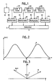
- This device comprises several delay lines, for example three, LR1 , LR2 and LR3 arranged in series, each delay line introducing a delay equal to the repetition period Tr of the pulses emitted at frequency Fr.
- Each delay line output and the input of the first LR1 are respectively connected to a circuit multiplication or weighting MO, M1, M2 and M3 in which the amplitude of the signal is multiplied or weighted respectively by a coefficient K0, K1, K2, and K3.
- the outputs of the multiplication circuits are connected to a summing circuit S which performs the sum of the weighted signals so as to obtain a filtered signal.
- the values of the coefficients K0, K1, K2 and K3 can be 1, -3, 3 and -1 respectively and the frequency transfer function of such a filter is of the form
- the module of the frequency response curve of such a filter is given by the diagram in FIG. 2.
- such a filter is known as a transverse filter and is of the type with cancellation on four pulses. , which corresponds to the Anglo-Saxon expression of "four-pulse canceler transverse filter".
- the samples X i to X i + 3 therefore correspond to a radar signal coming from a distance box located at a determined distance from the antenna of the radar equal to t / C if C is the speed of light.
- FIG. 3 makes it possible to understand the approach of the invention.
- such a multiplication circuit 10 is no longer necessary and is replaced by new values K′0, K′1, K′2, and K′3 of the multiplication coefficients used in the circuits M0 to M3, values which are fixed and which, for certain values of the frequency Fd, are easy to perform digitally.
- the z-transform of a discrete-time signal (x n ) is defined by the series:
- x n corresponds to the series of samples separated from each other by a repetition period Tr.
- FIG. 4 gives the canonical structure of such a transverse filter in the case of a weighting made on four pulses.
- the input of the operator circuit Z1 as well as the outputs of the operator circuits Z1, Z2 and Z3 are connected to multiplier circuits M′0 to M′3 which carry out the multiplication by the coefficients K′0 to K′3 respectively.
- Hi (z) and H ′ (z) have the same module, which means that we perform the same filtering with structure (C) as with structure (B) if we do not s 'is only of interest in the module, but in structure (C) the coefficients no longer depend on the rank of the sample in the repetition period and are therefore fixed values.
- the four coefficients K′0 to K′3 can be respectively equal to one of the following four groups - (-d, 3, 3d, -1) - (1, 3d, -3, -d) - (d, -3, -3d, 1) - (-1, -3d, 3, j)
- they can be respectively equal to: - (j, 3, -3d, -1) - (1, -3d, -3, j) - (-j, -3, 3d, 1) - (-1, 3d, 3, -d)
- the modulus of the frequency transfer function H ′ (f) is given by curve 12 in FIG. 5 which corresponds to curve 11 elimination of fixed echoes in Figure 2, but moved by -Fr / 4 on the frequency axis.
- Such a transfer function, the transmission maximum of which is at + Fr / 4 makes it possible to eliminate the echoes corresponding to the Doppler frequencies close to -Fr / 4.
- the modulus of the frequency transfer function H ′ (f) is given by curve 13 in FIG. 6 which corresponds to curve 11 for eliminating fixed echoes but displaced by + Fr / 4 over l 'frequency axis.
- Such a transfer function whose maximum transmission is at -Fr / 4 allows the filter to eliminate the echoes corresponding to the Doppler frequencies close to + Fr / 4.
- FIG. 7 is a diagram of a digital filtering device which implements the method of the invention in the case of simultaneous frequency offsets of + Fr / 4 and -Fr / 4 with processing on four pulses at using three memories each carrying a delay line.
- the signal to be filtered is presented in the form of its two real components I and imaginary Q which are first processed in two separate channels and then in a common part.
- Each separate channel comprises a memory 20 (or 21) which is made up, in the case of simultaneous processing on four samples, of three identical elementary memories 22, 24, 26 (or 23, 25, 27) which are provided for recording each, in the case of a radar signal, the sample codes corresponding to a repetition period Tr.
- the outputs of memories 22 and 24 (or 23 and 25) are connected respectively to adder circuits 28 and 30 (or 29 and 31) which carry out the operation multiplication by the coefficient 3.
- the common part includes adder circuits 32 to 39 and two module calculation circuits.
- the adder circuits 32 to 35 and 36, 39 have a direct input + and a complementary input - which completes the code applied to it. More precisely, the inputs (-) of the adder circuits 32 to 35 are connected respectively: - at the output of memory 26, - at the output of the adder circuit 31, - at the input of memory 22, and - at the output of memory 27.
- the outputs (+) of the adder circuits 32 to 35 are connected respectively: - at the output of the adder circuit 28, - at the input of memory 23, - at the output of the adder circuit 30, and - at the output of the adder circuit 29.
- Each output of the adding circuits 32 to 35 is connected to one of the two inputs of one of the adding circuits 36 to 39.
- the output of the adding circuit 32 is connected to the inputs (+) of the adding circuits 36 and 37;
- the output of the adder circuit 33 is connected to the input (-) of the circuit 36 and to the input (+) of the circuit 37;
- the output of circuit 34 is connected to the input (+) of circuit 38 and to the input (-) of circuit 31;
- the output of circuit 35 is connected to the input (+) of circuits 38 and 39.
- the outputs 42 and 45 of circuits 36 and 39 are connected to the two inputs of the module calculation circuit 41 while the outputs 43 and 44 are connected to the two inputs of the module calculation circuit 40.
- the respective coefficients which have been indicated above are -1, -3j, 3 and j, for the complex samples X3, X2, X1, XO.
- -1 (I3 + jQ3) - 3j (I2 + jQ2) + 3 (I1 + JQ1) + j (Io + JQo) either: - I3 + 3I1 - QO + 3Q2 + j (-Q3 + 3Q1 + IO - 3I2) , which corresponds for the real part to the output 42 of the circuit 36 and for the imaginary part to the output 45 of circuit 39.
- the circuit for calculating the module 40 therefore gives the module of the signal corresponding to the filter + Fr / 4 while the circuit 41 gives the module of the signal corresponding to the filter -Fr / 4.
- the description which has just been given in relation to FIG. 7 shows that the application of the invention to particular cases of filters makes it possible to achieve simple digital devices, easy to produce and using only elementary circuits .
- the invention has been described in relation to a particular application in the field of radars. However, it is understood that the invention applies to the filtering of all types of electrical signals provided that they are sampled at a frequency at least equal to twice the maximum frequency of the useful spectrum so as to obtain the samples Xi separated by intervals of times equal to the sampling period.
- each transverse filter having an appropriate transfer function so that the sum transfer functions lead to the global transfer function sought.
Abstract
L'invention concerne un procédé et des dispositifs pour décaler en fréquence d'une valeur Fd le module de la fonction de transfert d'un filtre transverse.The invention relates to a method and devices for shifting the modulus of the transfer function of a transverse filter by a value Fd.
Dans un filtre transverse qui comprend trois lignes à retard Z1 Z2 et Z3 en série et quatre multiplicateurs M′0 à M′3, dont les coefficients multiplicateurs K0 à K3 sont prévus pour éliminer les signaux aux fréquences voisines de la fréquence zéro et des multiples entiers de la fréquence de répétition Fr des échantillons Xi, le procédé consiste à remplacer les coefficients multiplicateurs K0 à K3 par des coefficients K′0 à K′3 qui se déduisent des premiers en les multipliant par des coefficients fixes,
e3jr, e2jr, ejr et 1 avec r = 2πFd/FrIn a transverse filter which comprises three delay lines Z1 Z2 and Z3 in series and four multipliers M′0 to M′3, whose multiplier coefficients K0 to K3 are provided for eliminating the signals at frequencies close to frequency zero and multiples integers of the repetition frequency Fr of samples X i , the method consists in replacing the multiplying coefficients K0 to K3 by coefficients K′0 to K′3 which are deduced from the former by multiplying them by fixed coefficients,
e 3jr , e 2jr , e jr and 1 with r = 2πFd / Fr
L'invention est notamment applicable à l'élimination dans les signaux radar de certains échos indésirables. 
Description
L'invention concerne un procédé pour décaler en fréquence le module de la fonction de transfert d'un filtre du type numérique et à structure transverse ; elle concerne également des dispositifs pour mettre en oeuvre ledit procédé.The invention relates to a method for shifting in frequency the module of the transfer function of a filter of the digital type and with transverse structure; it also relates to devices for implementing said method.
Les filtres de fréquence de signaux électriques sont utilisés dans de nombreux domaines de l'électronique et notamment dans le traitement des signaux radar pour éliminer par exemple les échos fixes ou pour détecter des échos ayant des caractéristiques déterminées telles qu'une vitesse radiale. Ce mode de traitement est par exemple utilisé dans les radars Doppler cohérents à impulsions à vitesse ambiguë constante qui permettent, en mettant à profit l'effet Doppler, de déceler les obstacles mobiles qui donnent naissance à des signaux radar de faible amplitude au milieu d'obstacles fixes correspondant à des signaux radar de grande amplitude. En effet, dans ces radars à impulsions les ondes reçues après réflexion sur les obstacles mobiles sont affectés d'une phase qui varie d'une période de répétition à la suivante alors que les ondes reçues des obstacles fixes ne présentent pas une telle variation du déphasage. De ce fait, les signaux correspondant aux obstacles mobiles ont, après démodulation, des composantes qui varient sinusoïdalement à une fréquence fd appelée fréquence Doppler, qui est liée à la vitesse radiale v et à la longueur d'onde e du radar par la formule Fd = 2v/e. Les signaux qui correspondent à des obstacles fixes ont une amplitude constante et leur spectre est constitué par une série de raies discrètes aux fréquences O,Fr 2Fr,...nFr, Fr étant la fréquence de répétition des impulsions émises. Par ailleurs, le spectre des signaux correspondant à des obstacles mobiles se compose de raies discrètes du type mFr -+Fd.Frequency filters of electrical signals are used in many fields of electronics and in particular in the processing of radar signals to eliminate for example fixed echoes or to detect echoes having determined characteristics such as a radial speed. This processing mode is for example used in coherent Doppler radars with constant ambiguous speed pulses which make it possible, by taking advantage of the Doppler effect, to detect mobile obstacles which give rise to radar signals of low amplitude in the middle of fixed obstacles corresponding to large amplitude radar signals. Indeed, in these pulse radars the waves received after reflection on the moving obstacles are affected by a phase which varies from one repetition period to the next while the waves received from the fixed obstacles do not exhibit such a variation in the phase shift. . As a result, the signals corresponding to the mobile obstacles have, after demodulation, components which vary sinusoidally at a frequency fd called the Doppler frequency, which is linked to the radial speed v and to the wavelength e of the radar by the formula Fd = 2v / e. The signals which correspond to fixed obstacles have a constant amplitude and their spectrum consists of a series of discrete lines at frequencies O, Fr 2Fr, ... nFr, Fr being the repetition frequency of the transmitted pulses. In addition, the spectrum of the signals corresponding to mobile obstacles is made up of discrete lines of the mFr - + Fd type.
On comprend alors qu'il est possible d'éliminer les signaux correspondant aux obstacles fixes en utilisant un filtre d'élimination des échos fixes qui ne laisse pas passer les signaux de fréquence O, Fr, 2Fr,...nFr. Il est également souhaitable d'éliminer dans certains radars, tels que les radars de surveillance du trafic aérien, les obstacles mobiles qui présentent des vitesses Doppler faibles par rapport aux vitesses des échos auxquels on s'intéresse, par exemple les nuages, ou encore des obstacles fixes fluctuants qui présentent une certaine vitesse Doppler, tels que les arbres agités par le vent. Ces différents échos parasites à faible vitesse sont mieux connus sous le vocable anglo-saxon de "clutter" que l'on a traduit par le terme "fouillis". Ces exemples montrent qu'il serait avantageux de disposer dans le domaine des radars de filtres dont on pourrait modifier aisément et simplement la fonction de transfert le long de l'axe des fréquences pour éliminer non seulement les échos fixes ou pseudo-fixes mais également ceux dont la vitesse radiale est très différente de celle des cibles auxquelles on s'intéresse.It is then understood that it is possible to eliminate the signals corresponding to the fixed obstacles by using a filter for eliminating the fixed echoes which does not allow the signals of frequency O, Fr, 2Fr, ... nFr to pass. It is also desirable to eliminate in certain radars, such as air traffic surveillance radars, mobile obstacles which have low Doppler velocities compared to the echo velocities of interest, for example clouds, or even fluctuating fixed obstacles with a certain Doppler speed, such as wind-blown trees. These various parasitic echoes at low speed are better known by the English term "clutter" which has been translated by the term "clutter". These examples show that it would be advantageous to have filters in the field of radars, the transfer function of which could be easily and simply modified along the frequency axis to eliminate not only fixed or pseudo-fixed echoes but also those whose radial speed is very different from that of the targets in which we are interested.
Dans les radars, les filtres sont souvent réalisés sous forme numérique, c'est-à-dire que les signaux à filtrer sont échantillonnés à une fréquence égale à la fréquence de répétition des impulsions émises par le radar, puis l'amplitude des échantillons est codée de manière à obtenir une succession de codes numériques; enfin, ces codes sont multipliés par des coefficients dont les valeurs définissent les caractéristiques du filtrage à obtenir.In radars, the filters are often made in digital form, that is to say that the signals to be filtered are sampled at a frequency equal to the repetition frequency of the pulses emitted by the radar, then the amplitude of the samples is coded so as to obtain a succession of digital codes; finally, these codes are multiplied by coefficients whose values define the characteristics of the filtering get.
Ces filtres dits numériques sont réalisés par exemple à l'aide de mémoires disposées en série qui enregistrent chacune les codes de tous les échantillons d'une période de répétition, de circuits multiplicateurs disposés à la sortie desdites mémoires pour multiplier les codes lus dans la mémoire associée par un coefficient approprié et d'un circuit d'addition pour effectuer la sommation des codes résultant des multiplications.These so-called digital filters are produced for example using memories arranged in series which each record the codes of all the samples of a repetition period, multiplier circuits arranged at the output of said memories to multiply the codes read from the memory associated by an appropriate coefficient and an addition circuit for summing the codes resulting from the multiplications.
De tels filtres numériques peuvent être utilisés dans des domaines autres que celui des radars, par exemple dans celui des signaux haute-fidélité, notamment lorsque de tels signaux sont sous forme numérique. Dans ces domaines, il existe aussi un besoin de modifier la fonction de transfert des filtres sur l'axe des fréquences sans pour autant modifier profondément la structure des filtres, par exemple pour étendre la bande de réjection du filtre.Such digital filters can be used in fields other than that of radars, for example in that of high-fidelity signals, in particular when such signals are in digital form. In these fields, there is also a need to modify the transfer function of the filters on the frequency axis without however profoundly modifying the structure of the filters, for example to extend the rejection band of the filter.
Un but de la presente invention est donc de mettre en oeuvre un procédé qui permet, dans un filtre transverse, de décaler en fréquence le module de la fonction de transfert dudit filtre.An object of the present invention is therefore to implement a method which makes it possible, in a transverse filter, to shift in frequency the module of the transfer function of said filter.
Un autre but de l'invention est de réaliser des dispositifs de mise en oeuvre du procédé qui, pour certaines valeurs du décalage en fréquence, soient simples à réaliser.Another object of the invention is to provide devices for implementing the method which, for certain values of the frequency offset, are simple to carry out.
L'invention se rapporte à un procédé pour décaler en fréquence d'une valeur Fd le module de la fonction de transfert d'un filtre transverse à n cellules dont les coefficients de multiplication sont KO... Ki... Kn caractérisé en ce qu'il consiste à multiplier le coefficient de rang i par un facteur
ej(n-i)r
avec i variant de o à n et
r =2πFd.Tr
si Tr est la période de répétition des échantillons appliqués au filtre transverse de manière à obtenir de nouveaux coefficients K′O...K′i...K′n.The invention relates to a method for shifting in frequency by a value Fd the modulus of the transfer function of a transverse filter with n cells whose multiplication coefficients are KO ... Ki ... Kn characterized in that it consists in multiplying the coefficient of rank i by a factor
e j (ni) r
with i varying from o to n and
r = 2πFd.Tr
if Tr is the repetition period of the samples applied to the transverse filter so as to obtain new coefficients K′O ... K′i ... K′n.
D'autres caractéristiques et avantages de la présente invention apparaîtront à la lecture de la description suivante d'exemples particuliers de réalisation, ladite description étant faite en relation avec les dessins joints dans lesquels :
- - la figure 1 est un schéma de principe d'un filtre transverse d'élimination des échos fixes ,
- - la figure 2 est un diagramme montrant le module de la fonction de transfert du filtre transverse de la figure 1,
- - la figure 3 est un diagramme vectoriel montrant deux positions d'un vecteur signal radar dans le plan complexe,
- - la figure 4 est un schéma de la structure canonique d'un filtre transverse selon l'invention,
- - la figure 5 est un diagramme montrant le module de la fonction de transfert d'un filtre transverse selon l'invention, qui élimine les échos de fréquences Doppler voisines de -Fr/4,
- - la figure 6 est un diagramme montrant le module de la fonction de transfert d'un filtre transverse selon l'invention qui élimine les échos de fréquences Doppler voisines de +Fr/4 et la figure 7 est un schéma de réalisation de deux filtres transverses aux fréquences +Fr/4 et -Fr/4.
- FIG. 1 is a block diagram of a transverse filter for eliminating fixed echoes,
- FIG. 2 is a diagram showing the module of the transfer function of the transverse filter of FIG. 1,
- FIG. 3 is a vector diagram showing two positions of a radar signal vector in the complex plane,
- FIG. 4 is a diagram of the canonical structure of a transverse filter according to the invention,
- FIG. 5 is a diagram showing the module of the transfer function of a transverse filter according to the invention, which eliminates echoes of Doppler frequencies close to -Fr / 4,
- - Figure 6 is a diagram showing the module of the transfer function of a transverse filter according to the invention which eliminates echoes of Doppler frequencies close to + Fr / 4 and Figure 7 is a diagram of two transverse filters at frequencies + Fr / 4 and -Fr / 4.
L'invention sera décrite dans une application particulière qui est celle du filtrage de signaux radar.The invention will be described in a particular application which is that of radar signal filtering.
Dans les traitements de ces signaux, il est connu de les filtrer, notamment pour éliminer les échos fixes, en utilisant un dispositif dont le schéma de principe est donné par la figure 1. Ce dispositif comprend plusieurs lignes à retard, par exemple trois, LR1, LR2 et LR3 disposées en série, chaque ligne à retard introduisant un retard égal à la période de répétition Tr des impulsions émises de fréquence Fr. Chaque sortie de ligne à retard ainsi que l'entrée de la première LR1 est connectée respectivement à un circuit de multiplication ou de pondération MO, M1, M2 et M3 dans lequel l'amplitude du signal est multipliée ou pondérée respectivement par un coefficient K0, K1, K2, et K3. Les sorties des circuits de multiplication sont connectées à un circuit de sommation S qui effectue la somme des signaux pondérés de manière à obtenir un signal filtré. Pour éliminer les échos fixes les valeurs des coefficients K0, K1, K2 et K3 peuvent être respectivement 1, -3, 3 et -1 et la fonction de transfert en fréquence d'un tel filtre est de la forme
|sin πFd.Tr| ³
formule dans laquelle Fd est la fréquence Doppler de l'écho. Le module de la courbe de réponse en fréquence d'un tel filtre est donné par le diagramme de la figure 2. Dans le domaine des radars, un tel filtre est connu sous le nom de filtre transverse et est du type à annulation sur quatre impulsions, ce qui correspond à l'expression anglo-saxonne de "four-pulse canceler transverse filter".In the processing of these signals, it is known to filter them, in particular to eliminate the fixed echoes, by using a device whose block diagram is given in FIG. 1. This device comprises several delay lines, for example three, LR1 , LR2 and LR3 arranged in series, each delay line introducing a delay equal to the repetition period Tr of the pulses emitted at frequency Fr. Each delay line output and the input of the first LR1 are respectively connected to a circuit multiplication or weighting MO, M1, M2 and M3 in which the amplitude of the signal is multiplied or weighted respectively by a coefficient K0, K1, K2, and K3. The outputs of the multiplication circuits are connected to a summing circuit S which performs the sum of the weighted signals so as to obtain a filtered signal. To eliminate fixed echoes the values of the coefficients K0, K1, K2 and K3 can be 1, -3, 3 and -1 respectively and the frequency transfer function of such a filter is of the form
| sin πFd.Tr | ³
formula in which Fd is the Doppler frequency of the echo. The module of the frequency response curve of such a filter is given by the diagram in FIG. 2. In the radar field, such a filter is known as a transverse filter and is of the type with cancellation on four pulses. , which corresponds to the Anglo-Saxon expression of "four-pulse canceler transverse filter".
Dans les radars modernes, un tel filtre est réalisé de manière numérique, ce qui signifie que les signaux vidéo-fréquence du radar sont échantillonnés à la fréquence Fr, et codés numériquement pour obtenir des codes Xi. Ces codes sont enregistrés dans des mémoires qui réalisent les lignes à retard LR1, LR2, et LR3 de la figure 1. Les circuits de multiplication MO, M1, M2 et M3 ainsi que le circuit de sommation S sont également réalisés de manière numérique de sorte que pour un code Xi à l'entrée de la ligne à retard ou mémoire LR1, on obtient un code Si à la sortie du circuit S.In modern radars, such a filter is performed digitally, which means that the radar video-frequency signals are sampled at the frequency Fr, and digitally coded to obtain Xi codes. These codes are recorded in memories which produce the delay lines LR1, LR2, and LR3 of FIG. 1. The multiplication circuits MO, M1, M2 and M3 as well as the summing circuit S are also produced digitally so that for a code Xi at the input of the delay line or memory LR1, a code Si is obtained at the output of the circuit S.
Plus précisément, à un instant donné ti+3, le signal Si +3 à la sortie du circuit de sommation S sera donné par :
Si+3 = KO.Xi+3 + K1.Xi+2 + K2.Xi+1 + K3 Xi
formule dans laquelle :
- Xi est l'amplitude de l'échantillon à l'instant t de la récurrence de rang (i)
- Xi+1 est l'amplitude de l'échantillon à l'instant t de la récurrence de rang (i + 1) c'est-à-dire une période Tr plus tard,
- Xi+2 est l'amplitude de l'échantillon à l'instant t de la récurrence de rang (i + 2) c'est à dire deux périodes Tr plus tard,
- Xi+3 est l'amplitude de l'échantillon à l'instant t de la récurrence de rang (i + 3) c'est-à-dire trois périodes Tr plus tard.
S i + 3 = KO.X i + 3 + K1.X i + 2 + K2.X i + 1 + K3 X i
formula in which:
- X i is the amplitude of the sample at time t of the recurrence of rank (i)
- X i + 1 is the amplitude of the sample at time t of the recurrence of rank (i + 1), i.e. a period Tr later,
- X i + 2 is the amplitude of the sample at time t of the rank recurrence (i + 2), ie two periods Tr later,
- X i + 3 is the amplitude of the sample at time t of the recurrence of rank (i + 3), that is to say three periods Tr later.
Les échantillons Xi à Xi+3 correspondent donc à un signal radar provenant d'une case de distance située à une distance déterminée de l'antenne du radar égale à t/C si C est la vitesse de la lumière.The samples X i to X i + 3 therefore correspond to a radar signal coming from a distance box located at a determined distance from the antenna of the radar equal to t / C if C is the speed of light.
Ce que l'invention propose de réaliser est de décaler la fonction de transfert de ce filtre, dont la réponse en fréquence est montrée sur la figure 2, le long de l'axe des fréquences d'une valeur f, ce décalage étant obtenu de manière simple avec un minimum de moyens supplémentaires.What the invention proposes to achieve is to shift the transfer function of this filter, the frequency response of which is shown in FIG. 2, along the axis frequencies of a value f, this offset being obtained in a simple manner with a minimum of additional means.
La figure 3 permet de comprendre la démarche de l'invention. Sur cette figure, un signal radar Xi à la récurrence i peut être représenté sous la forme d'un vecteur Vi défini par ses composantes I et Q dans le plan complexe : Xi = Ii + JQi. A la récurrence suivante (i + 1), le vecteur sera devenu Vi+1 et correspondra au vecteur Vi mais avec une rotation r = 2πFd/Fr si Fd est la fréquence Doppler de l'écho. On comprendra alors que cet écho serait vu comme un écho fixe si, à chaque récurrence, on le déphasait de l'angle r dont il aurait tourné, ce qui revient à multiplier le signal radar :
Xi par 1
Xi+1 par e-jr
Xi+2 par e-2jr
Xi+3 par e-3jr FIG. 3 makes it possible to understand the approach of the invention. In this figure, a radar signal Xi at the recurrence i can be represented in the form of a vector Vi defined by its components I and Q in the complex plane: Xi = Ii + JQi. At the next recurrence (i + 1), the vector will have become Vi + 1 and will correspond to the vector Vi but with a rotation r = 2πFd / Fr if Fd is the Doppler frequency of the echo. We will then understand that this echo would be seen as a fixed echo if, at each recurrence, it was out of phase with the angle r which it would have rotated, which amounts to multiplying the radar signal:
X i by 1
X i + 1 by e -jr
X i + 2 by e -2d
X i + 3 by e -3d
On aurait ainsi obtenu une translation de fréquence du filtre d'élimination des échos fixes d'une valeur Fd. Une manière pour réaliser une telle translation est d'effectuer les multiplications à l'entrée du filtre transverse de la figure 1, c'est-à-dire en faisant précéder la ligne à retard LR1 d'un circuit de multiplication 10 qui a été représenté par un rectangle en tirets. Une telle solution conduit à un circuit de multiplication 10 qui est assez complexe car le coefficient change à chaque récurrence et qui est assez coûteux en nombre de circuits logiques et en temps de traitement.We would thus have obtained a frequency translation of the filter for eliminating fixed echoes by a value Fd. One way to carry out such a translation is to carry out the multiplications at the input of the transverse filter of FIG. 1, that is to say by preceding the delay line LR1 with a
Dans le dispositif de l'invention, un tel circuit de multiplication 10 , n'est plus nécessaire et est remplacé par de nouvelles valeurs K′0, K′1, K′2, et K′3 des coefficients de multiplication utilisés dans les circuits M0 à M3, valeurs qui sont fixes et qui, pour certaines valeurs de la fréquence Fd sont faciles à réaliser de manière numérique.In the device of the invention, such a
Les développements mathématiques qui vont suivre ont pour but de déterminer les coefficients K′0 à K′3. A cet effet, il est fait appel à la transformée en z qui est par exemple définie dans le livre intitulé "LES FILTRES NUMERIQUES" de R. BOITE et H. LEICH et édité par MASSON en 1980 - chapitre II.The mathematical developments which will follow are intended to determine the coefficients K′0 to K′3. To this end, use is made of the z-transform which is for example defined in the book entitled "THE NUMERICAL FILTERS" by R. BOITE and H. LEICH and published by MASSON in 1980 - chapter II.
La transformée en z d'un signal à temps discret (xn) est définie par la série :
Dans le cas d'un signal radar, xn correspond à la suite des échantillons séparés l'un de l'autre d'une période de répétition Tr.In the case of a radar signal, x n corresponds to the series of samples separated from each other by a repetition period Tr.
Les propriétés de la transformée en z permettent de démontrer que la fonction de transfert H(z) du filtre de la figure 1 (sans le circuit multiplicateur 10) s'écrit sous la forme :
H (z) = K0 + K1.z⁻¹ + K2.z⁻² + K3.z⁻³ (2)The properties of the transform in z allow to demonstrate that the transfer function H (z) of the filter of figure 1 (without the multiplier circuit 10) is written in the form:
H (z) = K0 + K1.z⁻¹ + K2.z⁻² + K3.z⁻³ (2)
Si l'on introduit le circuit multiplicateur 10, elle s'écrit sous la forme :
Hi(z) =KO.Ci+3 + K1.Ci+2.z⁻¹ + K2.Ci+1.z⁻² + K3.Ci.z⁻³
forme dans laquelle Ci = (ejr)i = (ej2πFd/Fr)i If we introduce the
Hi (z) = KO.C i + 3 + K1.C i + 2 .z⁻¹ + K2.C i + 1 .z⁻² + K3.C i .z⁻³
form in which Ci = (e jr ) i = (e j2πFd / Fr ) i
Le module Hi(z) est alors donné par
Hi(z) = KO.ej3r + K1.ej2r.z⁻¹ + K2.ejr.z⁻² + K3.z⁻³
ce qui correspond à un filtre de fonction de transfert H′(z) tel que
H′(z) = KO.ej3r + K1.ej2r.z⁻¹ + K2.ejr.z⁻² + K3.z⁻³ (3)The module Hi (z) is then given by
Hi (z) = KO.e j3r + K1.e j2r .z⁻¹ + K2.e jr .z⁻² + K3.z⁻³
which corresponds to a transfer function filter H ′ (z) such that
H ′ (z) = KO.e j3r + K1.e j2r .z⁻¹ + K2.e jr .z⁻² + K3.z⁻³ (3)
La comparaison des formules (2) et (3) montre que pour réaliser le décalage en fréquence fd du module de la fonction de transfert, il est suffisant de modifier les coefficients des circuits multiplicateurs M0 à M3 pour qu'ils deviennent
K′0 = K0.ej3r
K′1 = K1.ej2r
K′2 = K2.ejr
K′3 = K3The comparison of formulas (2) and (3) shows that to achieve the frequency offset fd of the module of the transfer function, it is sufficient to modify the coefficients of the multiplier circuits M0 to M3 so that they become
K′0 = K0.e j3r
K′1 = K1.e j2r
K′2 = K2.e jr
K′3 = K3
La figure 4 donne la structure canonique d'un tel filtre transverse dans le cas d'une pondération faite sur quatre impulsions. Sur cette figure, les lignes à retard LR1 à LR3 de la figure 1 sont schématisées par des opérateurs Z1 à Z3 en série qui réalisent chacun la transformée z⁻¹, ce qui correspond à effectuer un retard Tr de chaque échantillon Xi car :
z⁻¹ = e-j2πFd.Tr FIG. 4 gives the canonical structure of such a transverse filter in the case of a weighting made on four pulses. In this figure, the delay lines LR1 to LR3 of FIG. 1 are shown diagrammatically by operators Z1 to Z3 in series which each carry out the transform z⁻¹, which corresponds to effecting a delay Tr of each sample X i because:
z⁻¹ = e -j2πFd.Tr
L'entrée du circuit opérateur Z1 ainsi que les sorties des circuits opérateurs Z1, Z2 et Z3 sont connectés à des circuits multiplicateurs M′0 à M′3 qui effectuent respectivement la multiplication par les coefficients K′0 à K′3. Les sorties des circuits multiplicateurs M′0 à M′3 sont connectés à un circuit d'addition S′ qui fournit un signal filtré S′i+3 défini par :
S′i+3 = K′0.Xi+3 + K′1.Xi+2 + K′2. Xi+3 + K3.Xi
c'est-à-dire un signal dans lequel ont été éliminés les échos ayant des fréquences Doppler Fd.The input of the operator circuit Z1 as well as the outputs of the operator circuits Z1, Z2 and Z3 are connected to multiplier circuits M′0 to M′3 which carry out the multiplication by the coefficients K′0 to K′3 respectively. The outputs of the multiplier circuits M′0 to M′3 are connected to an addition circuit S ′ which provides a filtered signal S ′ i + 3 defined by:
S ′ i + 3 = K′0.X i + 3 + K′1.X i + 2 + K′2. X i + 3 + K3.X i
that is to say a signal in which the echoes having Doppler Fd frequencies have been eliminated.
La description de l'invention a été faite dans le cas particulier d'un filtre transverse traitant quatre impulsions mais il est clair que l'invention peut être mise en oeuvre pour un nombre d'impulsions quelconque. Ainsi, pour un nombre L d'impulsions à traiter simultanément, on a les fonctions de transfert en z suivantes selon les structures :
- (A) structure classique d'élimination des échos fixes :

- (B) structure avec multiplications en tête

- (C) structure avec multiplication en sortie

- (A) classic structure for eliminating fixed echoes:
- (B) structure with head multiplications
- (C) structure with multiplication at output
On constate alors que Hi(z) et H′(z) ont le même module, ce qui signifie que l'on réalise le même filtrage avec la structure (C) qu'avec la structure (B) si l'on ne s'intéresse qu'au module, mais dans la structure (C) les coefficients ne dépendent plus du rang de l'échantillon dans la période de répétition et sont donc des valeurs fixes.We then observe that Hi (z) and H ′ (z) have the same module, which means that we perform the same filtering with structure (C) as with structure (B) if we do not s 'is only of interest in the module, but in structure (C) the coefficients no longer depend on the rank of the sample in the repetition period and are therefore fixed values.
On remarque que, pour certaines valeurs de la fréquence Doppler Fd par rapport à la fréquence de répétition Fr, on obtient des valeurs des coefficients K′0 à K′3 qui sont des nombres entiers conduisant à des multiplications simples. Il en est ainsi lorsque Fd est égale à +Fr/4 ou à -Fr/4 ; dans le premier cas, les quatre coefficients K′0 à K′3 peuvent être respectivement égaux à l'un des quatre groupes suivants
- (-j, 3, 3j, -1)
- (1, 3j, -3, -j)
- (j, -3, -3j, 1)
- (-1, -3j, 3, j)
Dans le deuxième cas, ils peuvent être respectivement égaux à :
- (j, 3, -3j, -1)
- (1,-3j, -3, j)
- (-j, -3, 3j, 1)
- (-1, 3j, 3, -j)It is noted that, for certain values of the Doppler frequency Fd with respect to the repetition frequency Fr, we obtain values of the coefficients K′0 to K′3 which are whole numbers leading to simple multiplications. This is so when Fd is equal to + Fr / 4 or to -Fr / 4; in the first case, the four coefficients K′0 to K′3 can be respectively equal to one of the following four groups
- (-d, 3, 3d, -1)
- (1, 3d, -3, -d)
- (d, -3, -3d, 1)
- (-1, -3d, 3, j)
In the second case, they can be respectively equal to:
- (j, 3, -3d, -1)
- (1, -3d, -3, j)
- (-j, -3, 3d, 1)
- (-1, 3d, 3, -d)
Dans le premier cas, le module de la fonction de transfert en fréquence H′(f) est donné par la courbe 12 de la figure 5 qui correspond à la courbe 11 d'élimination des échos fixes de la figure 2, mais déplacée de -Fr/4 sur l'axe des fréquences. Une telle fonction de transfert, dont le maximum de transmission est à +Fr/4 permet d'éliminer les échos correspondant aux fréquences Doppler voisines de -Fr/4.In the first case, the modulus of the frequency transfer function H ′ (f) is given by
Dans le second cas, le module de la fonction de transfert en fréquence H′(f) est donné par la courbe 13 de la figure 6 qui correspond à la courbe 11 d'élimination des échos fixes mais déplacée de +Fr/4 sur l'axe des fréquences. Une telle fonction de transfert dont le maximum de transmission est à -Fr/4 permet au filtre d'éliminer les échos correspondant aux fréquences Doppler voisines de +Fr/4.In the second case, the modulus of the frequency transfer function H ′ (f) is given by
La figure 7 est un schéma d'un dispositif numérique de filtrage qui met en oeuvre le procédé de l'invention dans le cas de décalages simultanés en fréquence de +Fr/4 et -Fr/4 avec un traitement sur quatre impulsions à l'aide de trois mémoires réalisant chacune une ligne à retard.FIG. 7 is a diagram of a digital filtering device which implements the method of the invention in the case of simultaneous frequency offsets of + Fr / 4 and -Fr / 4 with processing on four pulses at using three memories each carrying a delay line.
Le signal à filtrer est présenté sous la forme de ses deux composantes réelle I et imaginaire Q qui sont d'abord traitées dans deux voies séparées puis dans une partie commune. Chaque voie séparée comprend une mémoire 20 (ou 21) qui est constituée, dans le cas d'un traitement simultané sur quatre échantillons, de trois mémoires élémentaires identiques 22, 24, 26 (ou 23, 25, 27) qui sont prévues pour enregistrer chacune, dans le cas d'un signal radar, les codes des échantillons correspondant à une période de répétition Tr. Les sorties des mémoires 22 et 24 (ou 23 et 25) sont connectées respectivement à des circuits additionneurs 28 et 30 (ou 29 et 31) qui réalisent l'opération multiplication par le coefficient 3.The signal to be filtered is presented in the form of its two real components I and imaginary Q which are first processed in two separate channels and then in a common part. Each separate channel comprises a memory 20 (or 21) which is made up, in the case of simultaneous processing on four samples, of three identical
La partie commune comprend des circuits additionneurs 32 à 39 et deux circuits de calcul de module. Les circuits additionneurs 32 à 35 et 36, 39, ont une entrée directe + et une entrée complémentaire - qui réalise le complément du code qui lui est appliqué. De manière plus précise, les entrées (-) des circuits additionneurs 32 à 35 sont connectées respectivement :
- à la sortie de la mémoire 26,
- à la sortie du circuit additionneur 31,
- à l'entrée de la mémoire 22, et
- à la sortie de la mémoire 27.The common part includes
- at the output of
- at the output of the
- at the input of
- at the output of
De même, les sorties (+) des circuits additionneurs 32 à 35 sont connectées respectivement :
- à la sortie du circuit additionneur 28,
- à l'entrée de la mémoire 23,
- à la sortie du circuit additionneur 30, et
- à la sortie du circuit additionneur 29.Similarly, the outputs (+) of the
- at the output of the
- at the input of
- at the output of the
- at the output of the
Chaque sortie des circuits additionneurs 32 à 35 est connectée à une des deux entrées d'un des circuits additionneurs 36 à 39. Ainsi, la sortie du circuit additionneur 32 est connectée aux entrées (+) des circuits additionneurs 36 et 37 ; la sortie du circuit additionneur 33 est connectée à l'entrée (-) du circuit 36 et à l'entrée (+) du circuit 37 ; la sortie du circuit 34 est connectée à l'entrée (+) du circuit 38 et à l'entrée (-) du circuit 31 ; enfin, la sortie du circuit 35 est connectée à l'entrée (+) des circuits 38 et 39.Each output of the adding
Les sorties 42 et 45 des circuits 36 et 39 sont connectées aux deux entrées du circuit de calcul du module 41 tandis que les sorties 43 et 44 sont connectées aux deux entrées du circuit de calcul de module 40.The
Si on appelle respectivement IO, I1, I2 et I3 les codes des échantillons à l'entrée de la mémoire 22 et aux sorties des mémoires 22, 24 et 26 et QO, Q1, Q2 et Q3 les codes des échantillons à l'entrée de la mémoire 21 et aux sorties des mémoires 23, 25 et 27, on peut voir que l'on a les codes suivants à la sortie des circuits 36 à 39.
- à la sortie 42 du circuit additionneur 36 :
- I3 + 3I1 - QO + 3Q2 ;
- à la sortie 45 du circuit additionneur 39 :
- Q3 + 3Q1 + IO - 3I2 ;
- à la sortie 43 du circuit additionneur 37 :
- I3 + 3I1 +QO - 3Q2 ;
- à la sortie 44 du circuit additionneur 38 :
- Q3 + 3Q1 - IO +3I2.If IO, I1, I2 and I3 respectively call the codes of the samples at the input of
- at
- I3 + 3I1 - QO + 3Q2;
- at output 45 of adder circuit 39:
- Q3 + 3Q1 + IO - 3I2;
- at
- I3 + 3I1 + QO - 3Q2;
- at output 44 of adder circuit 38:
- Q3 + 3Q1 - IO + 3I2.
On a montré ci-dessus que, pour obtenir un filtre dit +Fr/4 il fallait, selon l'invention, multiplier les échantillons complexes X3, X2, X1, XO par les coefficients respectifs -1, 3j, 3, -j et faire une sommation des résultats des multiplications c'est-à-dire obtenir :
-1(I3+jQ3) + 3j(I2+jQ2) + 3(I1+JQ1) - j(Io+JQo)
soit :
-I3 + 3I1 + QO - 3Q2 +j(-Q3+3Q1-IO+3I2),
ce qui correspond pour la partie réelle à la sortie 43 du circuit 37 et pour la partie imaginaire à la sortie 44 du circuit 38.It has been shown above that, in order to obtain a so-called + Fr / 4 filter, it was necessary, according to the invention, to multiply the complex samples X3, X2, X1, XO by the respective coefficients -1, 3j, 3, -j and sum the results of the multiplications, i.e. obtain:
-1 (I3 + jQ3) + 3j (I2 + jQ2) + 3 (I1 + JQ1) - j (Io + JQo)
is :
-I3 + 3I1 + QO - 3Q2 + j (-Q3 + 3Q1-IO + 3I2),
which corresponds for the real part to the
En ce qui concerne le filtre dit -Fr/4, les coefficients respectifs qui ont été indiqués ci-dessus sont -1, -3j, 3 et j, pour les échantillons complexes X3, X2,X1, XO. A la sortie du circuit de sommation S′ de la figure 4, on obtient :
-1 (I3+jQ3) - 3j(I2+jQ2) + 3(I1+JQ1) + j(Io+JQo) soit : - I3 + 3I1 - QO + 3Q2 + j (-Q3 + 3Q1 + IO - 3I2), ce qui correspond pour la partie réelle à la sortie 42 du circuit 36 et pour la partie imaginaire à la sortie 45 du circuit 39.Regarding the filter called -Fr / 4, the respective coefficients which have been indicated above are -1, -3j, 3 and j, for the complex samples X3, X2, X1, XO. At the output of the summing circuit S ′ in FIG. 4, we obtain:
-1 (I3 + jQ3) - 3j (I2 + jQ2) + 3 (I1 + JQ1) + j (Io + JQo) either: - I3 + 3I1 - QO + 3Q2 + j (-Q3 + 3Q1 + IO - 3I2) , which corresponds for the real part to the
En conséquence de ce qui précède, le circuit de calcul du module 40 donne donc le module du signal correspondant au filtre +Fr/4 tandis que le circuit 41 donne le module du signal correspondant au filtre -Fr/4. La description qui vient d'être faite en relation avec la figure 7 montre que l'application de l'invention à des cas particuliers de filtres permet d'aboutir à des dispositifs numériques simples, faciles à réaliser et n'utilisant que des circuits élémentaires.As a consequence of the above, the circuit for calculating the
L'invention a été décrite en relation avec une application particulière dans le domaine des radars. Cependant on comprend que l'invention s'applique au filtrage de tous types de signaux électriques à condition de les échantillonner à une fréquence au moins égale à deux fois la fréquence maximum du spectre utile de manière à obtenir les échantillons Xi séparés par des intervalles de temps égaux à la période d'échantillonnage.The invention has been described in relation to a particular application in the field of radars. However, it is understood that the invention applies to the filtering of all types of electrical signals provided that they are sampled at a frequency at least equal to twice the maximum frequency of the useful spectrum so as to obtain the samples Xi separated by intervals of times equal to the sampling period.
Bien entendu, pour obtenir un filtre ayant une fonction de transfert donnée en mettant en oeuvre la présente invention, il est possible de mettre en parallèle plusieurs filtres transverses selon l'invention, chaque filtre transverse ayant une fonction de transfert appropriée de manière que la somme des fonctions de transfert aboutisse à la fonction de transfert globale recherchée.Of course, to obtain a filter having a given transfer function by implementing the present invention, it is possible to put in parallel several transverse filters according to the invention, each transverse filter having an appropriate transfer function so that the sum transfer functions lead to the global transfer function sought.
Claims (5)
- (-j, 3, 3j, -1)
- (1, 3j, -3, -j)
- (j, -3, -3j, 1)
- (-1, -3j, 3, j)2 - Method according to claim 1 for shifting the module of the transfer function of a frequency + Fr / 4 in a transverse filter with three cells, characterized in that the coefficients K′O, K′1, K′2 and K′3 can have the values of one of the following four groups, respectively:
- (-d, 3, 3d, -1)
- (1, 3d, -3, -d)
- (d, -3, -3d, 1)
- (-1, -3d, 3, j)
- (j, 3, -3j, -1)
- (1, -3j, -3, j)
- (-j, -3, 3j, 1)
- (-1, 3j, 3, -j)3 - Method according to claim 1 for shifting the module of the transfer function of a frequency -Fr / 4 in a transverse filter with three cells, characterized in that the coefficients K′O, K′1, K′2 and K′3 can have the values of one of the following groups, respectively:
- (j, 3, -3d, -1)
- (1, -3d, -3, j)
- (-j, -3, 3d, 1)
- (-1, 3d, 3, -d)
- une première voie et une deuxième voie de traitement pour traiter respectivement les codes successifs des composantes réelle I et imaginaire Q, chaque voie comportant trois mémoires (22, 24, 26 ou 23, 25, 27) prévues pour enregistrer chacune tous les codes successifs apparaissant pendant une durée Tr et pour être lus de manière à présenter simultanément en même temps qu'un code Io ou Qo, trois autres codes I1 ou Q1, I2 ou Q2, I3 ou Q3 correspondant au meme signal à filtrer,
- des circuits additionneurs (28 à 29) connectés pour recevoir les codes Io à I3 et QO à Q3 fournis respectivement par les premières et deuxièmes voies de traitement et pour calculer, en utilisant le module d'un groupe de coefficients définis dans l'une et l'autre revendications 2 et 3, les parties réelle et imaginaire d'un signal filtré correspondant au décalage +Fr/4 et d'un signal filtré correspondant au décalage -Fr/4, et
- des circuits 40 et 41 de calcul du module des deux signaux filtrés.4 - Device for implementing the method according to claims 2 and 3 so as to filter a complex signal I + jQ whose components are presented in the form of successive digital codes separated by time intervals Tr, characterized in that includes:
- a first channel and a second processing channel for respectively processing the successive codes of the real I and imaginary Q components, each channel comprising three memories (22, 24, 26 or 23, 25, 27) provided for recording each of the successive codes appearing for a duration Tr and to be read so as to present simultaneously, together with an Io or Qo code, three other codes I1 or Q1, I2 or Q2, I3 or Q3 corresponding to the same signal to be filtered,
- adding circuits (28 to 29) connected to receive the codes Io to I3 and QO to Q3 supplied respectively by the first and second processing channels and for calculating, using the module of a group of coefficients defined in one and the other claims 2 and 3, the real and imaginary parts of a filtered signal corresponding to the offset + Fr / 4 and of a filtered signal corresponding to the offset -Fr / 4, and
- circuits 40 and 41 for calculating the module of the two filtered signals.
. -I3 + 3I1 - Q0 + 3Q2 qui correspond à la partie réelle du signal de sortie du filtre décalé de +Fr/4,
. -Q3 + 3Q1 + IO - 3I2 qui correspond à la partie imaginaire du signal de sortie du filtre décalé de +Fr/4,
. -I3 + 3I1 + QO - 3Q2 qui correspond à la partie réelle du signal de sortie du filtre décalé de -Fr/4, et
. - Q3 + 3Q1 - IO + 3I2 qui correspond à la partie imaginaire du signal de sortie du filtre décalé de -Fr/4.5 - Device according to claim 4, characterized in that the adder circuits (28 to 39) are provided for making the following sums:
. -I3 + 3I1 - Q0 + 3Q2 which corresponds to the real part of the filter output signal offset by + Fr / 4,
. -Q3 + 3Q1 + IO - 3I2 which corresponds to the imaginary part of the filter output signal offset by + Fr / 4,
. -I3 + 3I1 + QO - 3Q2 which corresponds to the real part of the filter output signal shifted by -Fr / 4, and
. - Q3 + 3Q1 - IO + 3I2 which corresponds to the imaginary part of the output signal of the filter shifted by -Fr / 4.
Applications Claiming Priority (2)
| Application Number | Priority Date | Filing Date | Title |
|---|---|---|---|
| FR8803524 | 1988-03-18 | ||
| FR8803524A FR2628909B1 (en) | 1988-03-18 | 1988-03-18 | METHOD AND DEVICES FOR TRANSLATION ALONG THE FREQUENCY AXIS OF THE MODULE OF THE TRANSFER FUNCTION OF A FILTER |
Publications (2)
| Publication Number | Publication Date |
|---|---|
| EP0333566A1 true EP0333566A1 (en) | 1989-09-20 |
| EP0333566B1 EP0333566B1 (en) | 1992-09-23 |
Family
ID=9364391
Family Applications (1)
| Application Number | Title | Priority Date | Filing Date |
|---|---|---|---|
| EP89400675A Expired - Lifetime EP0333566B1 (en) | 1988-03-18 | 1989-03-10 | Method and devices for the translation along the frequency axis of the modulus of the transfer function of a filter |
Country Status (4)
| Country | Link |
|---|---|
| US (1) | US4965584A (en) |
| EP (1) | EP0333566B1 (en) |
| DE (1) | DE68902937T2 (en) |
| FR (1) | FR2628909B1 (en) |
Families Citing this family (2)
| Publication number | Priority date | Publication date | Assignee | Title |
|---|---|---|---|---|
| DE4013684C2 (en) * | 1990-04-28 | 1994-04-07 | Honeywell Elac Nautik Gmbh | Method and circuit arrangement for the detection of interference signals |
| DE10115607A1 (en) * | 2001-03-29 | 2002-10-02 | Valeo Schalter & Sensoren Gmbh | Method and device for the detection of objects in range cells by means of radar signals |
Citations (2)
| Publication number | Priority date | Publication date | Assignee | Title |
|---|---|---|---|---|
| US4463356A (en) * | 1981-08-17 | 1984-07-31 | Sperry Corporation | Apparatus for control of clutter breakthrough in MTI radar |
| GB2173366A (en) * | 1985-04-05 | 1986-10-08 | Grass Valley Group | A mixer controlled variable passband finite impulse response filter |
Family Cites Families (13)
| Publication number | Priority date | Publication date | Assignee | Title |
|---|---|---|---|---|
| US3877010A (en) * | 1967-10-26 | 1975-04-08 | Hughes Aircraft Co | Adaptable moving target processor |
| US4035799A (en) * | 1975-11-04 | 1977-07-12 | The United States Of America As Represented By The Secretary Of The Navy | Digital mean clutter doppler compensation system |
| US4153899A (en) * | 1976-03-10 | 1979-05-08 | Westinghouse Electric Corp. | MTI radar system and method |
| JPS5348496A (en) * | 1976-10-14 | 1978-05-01 | Mitsubishi Electric Corp | Moving target displaying system |
| US4173017A (en) * | 1977-04-11 | 1979-10-30 | The United States Of America As Represented By The Secretary Of The Army | Programmable signal processor for Doppler filtering |
| US4137532A (en) * | 1977-04-29 | 1979-01-30 | Westinghouse Electric Corp. | VIP doppler filter bank signal processor for pulse doppler radar |
| JPS5964912A (en) * | 1982-10-05 | 1984-04-13 | Nec Corp | Digital filter |
| JPS6024477A (en) * | 1983-07-21 | 1985-02-07 | Nec Corp | Radar signal processing apparatus |
| US4616229A (en) * | 1983-09-30 | 1986-10-07 | Westinghouse Electric Corp. | System and method of compensating a doppler processor for input unbalance and an unbalance measuring sensor for use therein |
| US4694298A (en) * | 1983-11-04 | 1987-09-15 | Itt Gilfillan | Adaptive, fault-tolerant narrowband filterbank |
| US4709236A (en) * | 1985-05-08 | 1987-11-24 | Westinghouse Electric Corp. | Selectable doppler filter for radar systems |
| EP0227457B1 (en) * | 1985-12-23 | 1993-09-15 | Nec Corporation | Radar system |
| US4783660A (en) * | 1986-09-29 | 1988-11-08 | Signatron, Inc. | Signal source distortion compensator |
-
1988
- 1988-03-18 FR FR8803524A patent/FR2628909B1/en not_active Expired - Lifetime
-
1989
- 1989-03-10 DE DE8989400675T patent/DE68902937T2/en not_active Expired - Fee Related
- 1989-03-10 EP EP89400675A patent/EP0333566B1/en not_active Expired - Lifetime
- 1989-03-20 US US07/325,586 patent/US4965584A/en not_active Expired - Fee Related
Patent Citations (2)
| Publication number | Priority date | Publication date | Assignee | Title |
|---|---|---|---|---|
| US4463356A (en) * | 1981-08-17 | 1984-07-31 | Sperry Corporation | Apparatus for control of clutter breakthrough in MTI radar |
| GB2173366A (en) * | 1985-04-05 | 1986-10-08 | Grass Valley Group | A mixer controlled variable passband finite impulse response filter |
Non-Patent Citations (3)
| Title |
|---|
| IEEE TRANSACTIONS ON AUDIO AND ELECTROACOUSTICS, vol. AU-19, no. 1, mars 1971, pages 72-77; W. ROECKER: "The application of digital filters for moving target indication" * |
| PATENT ABSTRACTS OF JAPAN, vol. 2, no. 84, 8 juillet 1978, page 3606 E 78; & JP-A-53 48 496 (MITSUBISHI DENKI K.K.) 01-05-1978 * |
| RCA REVIEW, vol. 32, no. 3, septembre 1971, pages 402-428; T. MURAKAMI et al.: "Clutter suppression by use of weighted pulse trains" * |
Also Published As
| Publication number | Publication date |
|---|---|
| US4965584A (en) | 1990-10-23 |
| DE68902937T2 (en) | 1993-02-25 |
| EP0333566B1 (en) | 1992-09-23 |
| FR2628909A1 (en) | 1989-09-22 |
| FR2628909B1 (en) | 1990-07-13 |
| DE68902937D1 (en) | 1992-10-29 |
Similar Documents
| Publication | Publication Date | Title |
|---|---|---|
| EP0036348B1 (en) | Active detection system by means of simultaneous emission of pulsed frequencies | |
| EP0932836B1 (en) | Method for pulse compression with a stepped frequency waveform | |
| EP0877260A1 (en) | Method for processing the received signal of a SAR radar with frequency ramps | |
| FR2587819A1 (en) | DEVICE FOR CALCULATING A DISCRETE, SLIDING, NON-RECURSIVE FOURIER TRANSFORMATION AND APPLICATION THEREOF TO A RADAR SYSTEM | |
| CA1263756A (en) | Device for calculating discrete fourier transforms and its application to pulse compressions in a radar system | |
| EP0884605A1 (en) | Processing method for the received signal of a synthetic aperture radar of the DERAMP type | |
| FR2525054A1 (en) | TRANSMITTER DESIGNED FOR TRANSMITTING MODULATED FREQUENCY SIGNALS | |
| EP0207859A1 (en) | Discrete and shifting Fourier transform calculating device, for using in a radar system | |
| EP3671250B1 (en) | Digital interferometer with sub-sampling | |
| EP0068909B1 (en) | Method and device to reduce the interference signal power received by the side lobes of a radar antenna | |
| EP0493189B1 (en) | Digitally coded impulse signal processing | |
| EP0334711B1 (en) | Apparatus for elimination of moving clutter in a radar | |
| FR2652654A1 (en) | ULTRASONIC ECHOGRAPHER USING A DIGITAL RECEIVE WAY FORMATION DEVICE. | |
| EP0147305B1 (en) | Discrimination apparatus for radar echos | |
| EP0333566B1 (en) | Method and devices for the translation along the frequency axis of the modulus of the transfer function of a filter | |
| EP1940023A2 (en) | Bank of cascadable digital filters, and reception circuit including such a bank of cascaded filters | |
| FR2632420A1 (en) | METHOD AND APPARATUS FOR COMPENSATING FOR SCALE SPEED IN COHERENT DOPPLER RADAR WITH VARIABLE AMBIGE SPEED | |
| FR2629602A1 (en) | DEVICE FOR PROCESSING SIGNALS OF A RADAR WITH A SIDE VISION, AND RADAR SYSTEM COMPRISING SUCH A DEVICE | |
| EP0010481B1 (en) | Method of and device for displaying moving targets, in particular in a variable prf radar | |
| EP1326091B1 (en) | Method for improving the quality of a radar image | |
| FR3075416A1 (en) | DIGITAL INTERPOLATOR FILTER, RHYTHM CHANGE DEVICE AND CORRESPONDING RECEIVING EQUIPMENT | |
| CA1190614A (en) | Adaptive filtering system for eliminating one or several sinusoidal interference signals | |
| CA1339156C (en) | Procede d'emission reception radar pour la levee d'ambiguite distance, emetteur-recepteur mettant en oeuvre un tel procede | |
| EP0029760B1 (en) | Filter device and its use in radar display systems | |
| FR2739453A1 (en) | Adaptive search elimination system for pulse Doppler radar |
Legal Events
| Date | Code | Title | Description |
|---|---|---|---|
| PUAI | Public reference made under article 153(3) epc to a published international application that has entered the european phase |
Free format text: ORIGINAL CODE: 0009012 |
|
| AK | Designated contracting states |
Kind code of ref document: A1 Designated state(s): DE GB IT NL |
|
| 17P | Request for examination filed |
Effective date: 19900131 |
|
| 17Q | First examination report despatched |
Effective date: 19920303 |
|
| GRAA | (expected) grant |
Free format text: ORIGINAL CODE: 0009210 |
|
| AK | Designated contracting states |
Kind code of ref document: B1 Designated state(s): DE GB IT NL |
|
| PG25 | Lapsed in a contracting state [announced via postgrant information from national office to epo] |
Ref country code: NL Effective date: 19920923 |
|
| ITF | It: translation for a ep patent filed |
Owner name: JACOBACCI & PERANI S.P.A. |
|
| REF | Corresponds to: |
Ref document number: 68902937 Country of ref document: DE Date of ref document: 19921029 |
|
| GBT | Gb: translation of ep patent filed (gb section 77(6)(a)/1977) | ||
| PGFP | Annual fee paid to national office [announced via postgrant information from national office to epo] |
Ref country code: GB Payment date: 19930225 Year of fee payment: 5 Ref country code: DE Payment date: 19930225 Year of fee payment: 5 |
|
| NLV1 | Nl: lapsed or annulled due to failure to fulfill the requirements of art. 29p and 29m of the patents act | ||
| PLBI | Opposition filed |
Free format text: ORIGINAL CODE: 0009260 |
|
| 26 | Opposition filed |
Opponent name: ANT NACHRICHTENTECHNIK GMBH PATENTABTEILUNG Effective date: 19930619 |
|
| RAP2 | Party data changed (patent owner data changed or rights of a patent transferred) |
Owner name: THOMSON-CSF |
|
| PG25 | Lapsed in a contracting state [announced via postgrant information from national office to epo] |
Ref country code: GB Effective date: 19940310 |
|
| GBPC | Gb: european patent ceased through non-payment of renewal fee |
Effective date: 19940310 |
|
| PG25 | Lapsed in a contracting state [announced via postgrant information from national office to epo] |
Ref country code: DE Effective date: 19941201 |
|
| PLBO | Opposition rejected |
Free format text: ORIGINAL CODE: EPIDOS REJO |
|
| PLBN | Opposition rejected |
Free format text: ORIGINAL CODE: 0009273 |
|
| STAA | Information on the status of an ep patent application or granted ep patent |
Free format text: STATUS: OPPOSITION REJECTED |
|
| 27O | Opposition rejected |
Effective date: 19980410 |
|
| PG25 | Lapsed in a contracting state [announced via postgrant information from national office to epo] |
Ref country code: IT Free format text: LAPSE BECAUSE OF NON-PAYMENT OF DUE FEES;WARNING: LAPSES OF ITALIAN PATENTS WITH EFFECTIVE DATE BEFORE 2007 MAY HAVE OCCURRED AT ANY TIME BEFORE 2007. THE CORRECT EFFECTIVE DATE MAY BE DIFFERENT FROM THE ONE RECORDED. Effective date: 20050310 |