EP0332931A2 - Méthode pour l'obturation de tuyauteries par congelation et dispositif pour mise en oeuvre cette méthode - Google Patents
Méthode pour l'obturation de tuyauteries par congelation et dispositif pour mise en oeuvre cette méthode Download PDFInfo
- Publication number
- EP0332931A2 EP0332931A2 EP89103550A EP89103550A EP0332931A2 EP 0332931 A2 EP0332931 A2 EP 0332931A2 EP 89103550 A EP89103550 A EP 89103550A EP 89103550 A EP89103550 A EP 89103550A EP 0332931 A2 EP0332931 A2 EP 0332931A2
- Authority
- EP
- European Patent Office
- Prior art keywords
- pipeline
- air
- chamber
- cold air
- air outlet
- Prior art date
- Legal status (The legal status is an assumption and is not a legal conclusion. Google has not performed a legal analysis and makes no representation as to the accuracy of the status listed.)
- Withdrawn
Links
Images


Classifications
-
- F—MECHANICAL ENGINEERING; LIGHTING; HEATING; WEAPONS; BLASTING
- F16—ENGINEERING ELEMENTS AND UNITS; GENERAL MEASURES FOR PRODUCING AND MAINTAINING EFFECTIVE FUNCTIONING OF MACHINES OR INSTALLATIONS; THERMAL INSULATION IN GENERAL
- F16L—PIPES; JOINTS OR FITTINGS FOR PIPES; SUPPORTS FOR PIPES, CABLES OR PROTECTIVE TUBING; MEANS FOR THERMAL INSULATION IN GENERAL
- F16L55/00—Devices or appurtenances for use in, or in connection with, pipes or pipe systems
- F16L55/10—Means for stopping flow from or in pipes or hoses
- F16L55/103—Means for stopping flow from or in pipes or hoses by temporarily freezing liquid sections in the pipe
-
- F—MECHANICAL ENGINEERING; LIGHTING; HEATING; WEAPONS; BLASTING
- F25—REFRIGERATION OR COOLING; COMBINED HEATING AND REFRIGERATION SYSTEMS; HEAT PUMP SYSTEMS; MANUFACTURE OR STORAGE OF ICE; LIQUEFACTION SOLIDIFICATION OF GASES
- F25B—REFRIGERATION MACHINES, PLANTS OR SYSTEMS; COMBINED HEATING AND REFRIGERATION SYSTEMS; HEAT PUMP SYSTEMS
- F25B9/00—Compression machines, plants or systems, in which the refrigerant is air or other gas of low boiling point
- F25B9/02—Compression machines, plants or systems, in which the refrigerant is air or other gas of low boiling point using Joule-Thompson effect; using vortex effect
- F25B9/04—Compression machines, plants or systems, in which the refrigerant is air or other gas of low boiling point using Joule-Thompson effect; using vortex effect using vortex effect
Definitions
- the invention relates to a method for closing pipelines by locally freezing their contents by means of a cooling medium acting on the outer wall of the pipeline.
- devices which consist of two half-cylinder shells which are closed on all sides, through which liquid refrigerants are circulated or into which a solid refrigerant such as carbon dioxide snow is introduced (US Pat. Nos. 2,572,555 and GB) -PS 601 278). From the last-mentioned GB-PS 601 278 it is also known to support the effect of solid carbon dioxide by the simultaneous presence of liquids which do not freeze themselves at the required low temperatures, such as methyl alcohol. However, the effectiveness of such methods and devices is limited because of the partition wall present between the refrigerant and the pipeline to be frozen.
- a device with a chamber which likewise does not have a partition wall towards the pipeline, but which only has to be sealed against the pipeline to a limited extent because the gaseous refrigerant in its final state is at a greater or lesser distance anyway the chamber, which is designed as a so-called "cuff", is derived into the environment (GB-PS 1 209 144 and DE-PS 23 30 807.
- a liquid gas is used as the refrigerant, which is contained in a thin-walled container under low pressure in this After the pressure relief, the liquid gas, while still liquid, interacts with the pipeline and removes the so-called heat of vaporization.
- the invention is therefore based on the object of specifying a method of the type described at the outset with which direct cooling of the freeze-up is possible Pipeline is possible without toxic and / or otherwise hazardous gases (risk of explosion) being released into the environment.
- the object is achieved in the method described above according to the invention in that pressurized air is released to a temperature below the freezing point of the contents of the pipeline and the relaxed air is directed towards the outer wall of the pipeline.
- thermodynamic effect which is known per se, can be used with very particular advantage when freezing pipelines locally, so that there is no change in the ambient air due to the release of toxic and / or caustic liquids or of toxic and / or combustible (explosive) gases occur.
- a compressor with an air cooler and a pressure vessel is required to carry out such a method.
- Such units which are easy to transport, are commercially available as compressed air sources for spray guns or the like.
- a particularly effective method for the local freezing of pipes using ambient air is characterized in accordance with a further embodiment of the invention in that the compressed and cooled air is first passed substantially tangentially into a vortex tube with a cold air outlet in the form of an orifice and a warm air outlet and in this vortex tube is at least predominantly relaxed, with part of the relaxed air being cooled further by giving off heat to the remaining part of the relaxed air and being fed through the cold air outlet with the orifice to the pipeline to be frozen, and the remaining part of the air being heated by a corresponding heat absorption by the said warm air outlet is discharged.
- Vortex tube is - in itself - state of the art; it is also referred to in the literature as “Ranquesches vortex tube” (see Brockhaus “abc physics”, VEB FA Brockhaus Verlag, Leipzig, 1973, page 1738, keyword: “vortex tube”).
- This swirl tube will also called a chiller with no moving parts.
- the vortex tube has a poor efficiency and is still of no technical importance for refrigeration today.
- the invention also relates to a device for closing pipelines by locally freezing their contents by means of a chamber which can be attached to the pipeline and which can be connected to a source of a cooling medium via a gas inlet opening and has an interior space which is open to the pipeline and to the atmosphere but is closed except for a gas outlet.
- such a device is characterized according to the invention in that the source for the cooling medium is a compressed air source and a relaxation device for the compressed air arranged between the latter and the inlet opening of the chamber.
- the invention therefore consists in a particularly advantageous form in the use of a vortex tube known per se for a new purpose, namely for freezing pipelines through which media flows.
- the inside of the chamber has guide devices through which, in cooperation with the outer surface of the pipe, the cold air can be guided over the outer surface of the pipe along extended flow paths.
- the compressed air which is supplied, for example, by a portable small compressor, can be cooled to temperatures between approximately -30 ° C. and -50 ° C. before it flows into the freezer sleeve.
- This cooling of the air takes place without mechanical moving parts and without supplying other energies in the area of the vortex tube.
- the cooled compressed air in the said chamber cools the enclosed tube and the water contained therein far below the freezing point of the water, which leads to the formation of the required ice plug and the closure of the tube.
- an adjustable flow restrictor for the warm air flow in the warm air outlet of the vortex tube.
- the cooling air emerging from the chamber or sleeve which of course has not yet reached the temperature of the ambient air, back into the cooling circuit, i.e. to the compressor, or to feed them to a heat exchanger, through which the compressor air supplied to the vortex tube is already pre-cooled accordingly.
- the tube freezer 1 shown in FIG. 1 has a compressed air source 2 with a compressor 3.
- the compressed air source 2 is connected by means of two hoses 4 to two expansion devices 5, which are designed as vortex tubes 6.
- the vortex tubes 6 are in turn on cuff-shaped chambers 7 connected, which are placed around pipes 8. Due to the freezing effect by means of the chambers 7, a heating element 9 can be detached from a pipe network, which is indicated here by a riser pipe 10 and a down pipe 11. Due to the freezing points in the area of the chambers 7, there is no need to empty the entire system.
- the chambers 7 have a connecting piece 12 with a gas inlet opening 12a, to which the cold air outlet of the vortex tube 6 can be connected by means of positive connection elements 13.
- a circumferential channel 14 is formed on the inside, and in the area of the gas outlet opening 15 a tension screw 16 is provided, by means of which the chamber 7 can be brought to bear against the respective pipeline 8 (FIGS. 2 and 3).
- FIG. 3 shows schematically the manner in which a chamber 7 with a swirl tube 6 is attached to a pipe 8.
- the vortex tube 6 is connected to the hose 4 via a pipe socket 17.
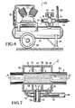
- Vortex tube 6 Details of the vortex tube 6 are shown in Figure 4, in which a partial section of the chamber 7 is shown in section and adjacent to the pipe 8.
- a vortex chamber 18 In the vortex tube 6 there is a vortex chamber 18, to which compressed air is supplied via an inlet channel 19.
- the inlet channel 19 opens into an annular channel 20, from which in turn numerous niche openings, not specified, lead into the swirl chamber 18 in the tangential direction.
- the swirl chamber 18 is delimited at one end by an aperture 23, which widens toward the cold air outlet 24 in the shape of a nozzle.
- the cold air outlet 24 is located at the end of a pipe socket 25 which is inserted into the connecting piece 12 of the chamber 7.
- the warm air outlet 26 is designed as an adjustable annular gap and represents a throttle point, the so-called "warm air throttle".
- the warm air outlet 26 is provided with an actuator 27, which is screwed into a bore 28 at the end 29 of the swirl tube 6 on the hot air side in its housing 30. According to the pitch of the thread, the outlet cross section of the hot air throttle can be adjusted by turning the actuator 27.
- the effect of the vortex tube is based on the formation of a strong vortex, the axis of which coincides with the axis of the vortex chamber 18. From the pressure and speed field of the vortex it follows that the temperature increases strongly towards the outside.
- the inner parts of the vertebra work by braking on the outer parts.
- the outlet temperatures of the air result from the distribution of the temperatures.
- the heat supplied to the warm part of the air is equal to the heat extracted from the cold part. Since the air flows into the pipe at supersonic speed, the air cools down from room temperature to -50 ° C, whereby temperatures up to 200 ° C can occur at the warm end.
- a connection piece 32 is provided in the area of the gas outlet opening 15 of the chamber 7, to which a hose 33 is attached.
- the hose 33 is connected to a pre-cooler 34, through the air suction opening 35 of which the air to be compressed by the compressor 3 is sucked in, pre-cooled and then introduced into the compressor 3. This makes it possible to allow the vortex tubes 6 to flow with pre-cooled compressed air, so that the freezing effect is increased.
- FIG. 6 shows a portable (mobile) compressor 3 with a cooling device 36 for the compressed air and a compressed air tank 37.
- This compressed air tank is provided with wheels 38, a support 39 and a handle bracket 40.
- a vortex tube 6 is structurally combined with the pressure vessel 37, the inlet channel 19 of which is directly connected to the compressed air vessel 37.
- the actuator 27, not shown here, is provided with an adjusting knob 41 protruding from the housing 30 of the swirl tube 6.
- the cold air outlet 24 located at the opposite end of the vortex tube is connected via a thermally insulated hose line 42 to at least one chamber 7, not shown in FIG. In the present case, only one vortex tube is required, and the cold air is distributed to the individual chambers 7 by a distributor, not shown here.
- the tube freezer 43 of Figure 6 also has two pressure gauges 44 and 45 for the detection of the characteristic pressures P1 and P2 here.
- Figure 7 shows a chamber 7 with a particularly strong cooling effect.
- the chamber 7 is divided in the direction of the axis A-A of the pipeline 8 to be frozen by baffles 7a and 7b into three sub-chambers 46, 47 and 48 which are connected to one another by openings 7c and 7b.
- the gas inlet opening 12a is assigned to the middle subchamber 47, and the gas outlet openings 15 are arranged in the subchambers 46 and 48 located at the ends. This ensures that the relaxed cold air is led around the pipeline several times. It is expedient to direct the cold air as directly as possible onto the surface 8a of the pipeline 8. Due to the cooling effect, a so-called ice plug 49 forms inside the pipeline 8, which reliably closes the pipeline 8.
- the chamber 7 In order to mount the chamber 7 on the pipeline 8, it is designed to be divided in an axial plane and provided with a hinge, which is indicated here by the dashed line 50.
- the chamber 7 consists of two half-shells.
- the gas outlet openings 15 are combined in a common manifold 51.
Applications Claiming Priority (4)
| Application Number | Priority Date | Filing Date | Title |
|---|---|---|---|
| DE8803407U DE8803407U1 (fr) | 1988-03-14 | 1988-03-14 | |
| DE8803407U | 1988-03-14 | ||
| DE3815416 | 1988-05-06 | ||
| DE19883815416 DE3815416C1 (fr) | 1988-03-14 | 1988-05-06 |
Publications (2)
| Publication Number | Publication Date |
|---|---|
| EP0332931A2 true EP0332931A2 (fr) | 1989-09-20 |
| EP0332931A3 EP0332931A3 (fr) | 1991-05-15 |
Family
ID=25867822
Family Applications (1)
| Application Number | Title | Priority Date | Filing Date |
|---|---|---|---|
| EP19890103550 Withdrawn EP0332931A3 (fr) | 1988-03-14 | 1989-03-01 | Méthode pour l'obturation de tuyauteries par congelation et dispositif pour mise en oeuvre cette méthode |
Country Status (3)
| Country | Link |
|---|---|
| EP (1) | EP0332931A3 (fr) |
| JP (1) | JPH0217297A (fr) |
| DE (1) | DE3815416C1 (fr) |
Cited By (3)
| Publication number | Priority date | Publication date | Assignee | Title |
|---|---|---|---|---|
| US5261619A (en) * | 1992-02-18 | 1993-11-16 | Bobrick Washroom Equipment, Inc. | Toilet tissue dispenser with lock |
| EP1273845A1 (fr) * | 2001-05-15 | 2003-01-08 | Rothenberger Werkzeuge Aktiengesellschaft | Dispositif de congélation pour tuyaux remplis de liquide |
| GB2547709A (en) * | 2016-02-29 | 2017-08-30 | Pttg Ltd | Freezing of pipes |
Families Citing this family (3)
| Publication number | Priority date | Publication date | Assignee | Title |
|---|---|---|---|---|
| SE9300907L (sv) * | 1993-03-18 | 1994-04-18 | Lothar Beise | Sätt och anordning för bildande av propp i rör |
| DE19516454A1 (de) * | 1995-05-04 | 1996-11-07 | Alexander Dr Flos | Sanitärrohr-Vereisungsvorrichtung |
| JP4201311B2 (ja) | 2002-03-12 | 2008-12-24 | 株式会社日立メディコ | 超音波診断装置 |
Citations (4)
| Publication number | Priority date | Publication date | Assignee | Title |
|---|---|---|---|---|
| GB1425050A (en) * | 1973-05-29 | 1976-02-18 | Flomatic Corp | Pipe freezing device |
| US4339926A (en) * | 1981-08-03 | 1982-07-20 | E. D. Bullard Company | Vortex tube |
| DE8223605U1 (de) * | 1982-08-21 | 1982-12-23 | Sanden, John A. van der, 5601 Eindhoven | Vorrichtung zur ausbildung eines gefrorenen verschlusspfropfens in einer rohrleitung |
| EP0232782A1 (fr) * | 1986-02-04 | 1987-08-19 | MAR-RESEARCH Gesellschaft für Forschung und Entwicklung mbH | Méthode et dispositif de refroidissement des aubes de turbines thermiques |
Family Cites Families (5)
| Publication number | Priority date | Publication date | Assignee | Title |
|---|---|---|---|---|
| GB601278A (en) * | 1945-10-12 | 1948-05-03 | Thomas Nicholas Young | Improvements relating to apparatus for use in freezing liquid-containing pipes |
| US2572555A (en) * | 1944-11-03 | 1951-10-23 | Freez Seal Equipment Company L | Water pipe repairing equipment |
| GB1209144A (en) * | 1966-11-25 | 1970-10-21 | Distillers Co Carbon Dioxide | Improvements in or relating to apparatus for freezing liquid in pipes |
| US3559423A (en) * | 1969-08-08 | 1971-02-02 | Werner Scheidler | Equipment for working on liquid-filled conduits |
| DE2330807C2 (de) * | 1973-06-16 | 1982-03-25 | Flomatic Corp., North Hoosick, N.Y. | Vorrichtung zum Einfrieren einer mediendurchströmten Rohrleitung |
-
1988
- 1988-05-06 DE DE19883815416 patent/DE3815416C1/de not_active Expired
-
1989
- 1989-03-01 EP EP19890103550 patent/EP0332931A3/fr not_active Withdrawn
- 1989-03-14 JP JP1059877A patent/JPH0217297A/ja active Pending
Patent Citations (4)
| Publication number | Priority date | Publication date | Assignee | Title |
|---|---|---|---|---|
| GB1425050A (en) * | 1973-05-29 | 1976-02-18 | Flomatic Corp | Pipe freezing device |
| US4339926A (en) * | 1981-08-03 | 1982-07-20 | E. D. Bullard Company | Vortex tube |
| DE8223605U1 (de) * | 1982-08-21 | 1982-12-23 | Sanden, John A. van der, 5601 Eindhoven | Vorrichtung zur ausbildung eines gefrorenen verschlusspfropfens in einer rohrleitung |
| EP0232782A1 (fr) * | 1986-02-04 | 1987-08-19 | MAR-RESEARCH Gesellschaft für Forschung und Entwicklung mbH | Méthode et dispositif de refroidissement des aubes de turbines thermiques |
Cited By (3)
| Publication number | Priority date | Publication date | Assignee | Title |
|---|---|---|---|---|
| US5261619A (en) * | 1992-02-18 | 1993-11-16 | Bobrick Washroom Equipment, Inc. | Toilet tissue dispenser with lock |
| EP1273845A1 (fr) * | 2001-05-15 | 2003-01-08 | Rothenberger Werkzeuge Aktiengesellschaft | Dispositif de congélation pour tuyaux remplis de liquide |
| GB2547709A (en) * | 2016-02-29 | 2017-08-30 | Pttg Ltd | Freezing of pipes |
Also Published As
| Publication number | Publication date |
|---|---|
| DE3815416C1 (fr) | 1989-10-12 |
| JPH0217297A (ja) | 1990-01-22 |
| EP0332931A3 (fr) | 1991-05-15 |
Similar Documents
| Publication | Publication Date | Title |
|---|---|---|
| EP0432583B1 (fr) | Dispositif de refroidissement | |
| DE3637071C2 (de) | Verfahren und Vorrichtung zum Verdichten von Gasen | |
| DE2734358A1 (de) | Kaelteerzeugungs-vorrichtung | |
| DE1953835A1 (de) | Vorrichtung fuer die Kryochirurgie | |
| DE2831199B2 (de) | Kryochinirgiegerät | |
| DE4202802A1 (de) | Vorrichtung zum kuehltrocknen von gasen | |
| DE3815416C1 (fr) | ||
| DE2005634A1 (fr) | ||
| DE19942265A1 (de) | Verdichteranlage und Verfahren zur Verdichtung eines Gases | |
| DE102005034826B4 (de) | Wärmepumpe sowie Verfahren zum Betrieb einer Wärmepumpe | |
| DE2252638B2 (de) | Speichervorrichtung zum ausgleichen wechselnden gasbedarfs | |
| DE3903009C2 (fr) | ||
| DE4340689C1 (de) | Verfahren zum Kühlen von Gasen | |
| DE3916025C2 (fr) | ||
| DE3511726A1 (de) | Vorrichtung zum absperren von gasrohren | |
| DE60108415T2 (de) | Vorrichtung und verfahren zur überführung einer kryogenen flüssigkeit | |
| DE2530198C3 (de) | Vorrichtung zum Trocknen von Gasen | |
| DE4034076A1 (de) | Vorrichtung zur expansion verfluessigter gase | |
| EP0316588A1 (fr) | Dispositif pour exposer l'extérieur d'une conduite de transport d'un fluide congelable à un moyen de refroidissement | |
| DE19624462A1 (de) | Einfriervorrichtung für flüssigkeitsgefüllte Rohrleitung | |
| DE19532741C1 (de) | Verfahren und Vorrichtung zum Auswechseln eines alten Absperrventiles | |
| DE1751714A1 (de) | Verfahren und Vorrichtung zum Erzeugen von Kaelte | |
| DE102004058137B3 (de) | Vorrichtung zum örtlichen Einfrieren von wassergefüllten Rohrleitungen | |
| WO2021214225A1 (fr) | Appareil et procédé de génération de températures cryogéniques et utilisation correspondante | |
| DE3008355A1 (de) | Verfahren und vorrichtung zum betreiben eines kuehlaggregats |
Legal Events
| Date | Code | Title | Description |
|---|---|---|---|
| PUAI | Public reference made under article 153(3) epc to a published international application that has entered the european phase |
Free format text: ORIGINAL CODE: 0009012 |
|
| AK | Designated contracting states |
Kind code of ref document: A2 Designated state(s): AT BE CH DE ES FR GB IT LI LU NL SE |
|
| PUAL | Search report despatched |
Free format text: ORIGINAL CODE: 0009013 |
|
| AK | Designated contracting states |
Kind code of ref document: A3 Designated state(s): AT BE CH DE ES FR GB IT LI LU NL SE |
|
| STAA | Information on the status of an ep patent application or granted ep patent |
Free format text: STATUS: THE APPLICATION IS DEEMED TO BE WITHDRAWN |
|
| 18D | Application deemed to be withdrawn |
Effective date: 19911106 |