EP0332931A2 - Method for plugging pipelines by freezing and device for carrying out this method - Google Patents
Method for plugging pipelines by freezing and device for carrying out this method Download PDFInfo
- Publication number
- EP0332931A2 EP0332931A2 EP89103550A EP89103550A EP0332931A2 EP 0332931 A2 EP0332931 A2 EP 0332931A2 EP 89103550 A EP89103550 A EP 89103550A EP 89103550 A EP89103550 A EP 89103550A EP 0332931 A2 EP0332931 A2 EP 0332931A2
- Authority
- EP
- European Patent Office
- Prior art keywords
- pipeline
- air
- chamber
- cold air
- air outlet
- Prior art date
- Legal status (The legal status is an assumption and is not a legal conclusion. Google has not performed a legal analysis and makes no representation as to the accuracy of the status listed.)
- Withdrawn
Links
Images


Classifications
-
- F—MECHANICAL ENGINEERING; LIGHTING; HEATING; WEAPONS; BLASTING
- F16—ENGINEERING ELEMENTS AND UNITS; GENERAL MEASURES FOR PRODUCING AND MAINTAINING EFFECTIVE FUNCTIONING OF MACHINES OR INSTALLATIONS; THERMAL INSULATION IN GENERAL
- F16L—PIPES; JOINTS OR FITTINGS FOR PIPES; SUPPORTS FOR PIPES, CABLES OR PROTECTIVE TUBING; MEANS FOR THERMAL INSULATION IN GENERAL
- F16L55/00—Devices or appurtenances for use in, or in connection with, pipes or pipe systems
- F16L55/10—Means for stopping flow in pipes or hoses
- F16L55/103—Means for stopping flow in pipes or hoses by temporarily freezing liquid sections in the pipe
-
- F—MECHANICAL ENGINEERING; LIGHTING; HEATING; WEAPONS; BLASTING
- F25—REFRIGERATION OR COOLING; COMBINED HEATING AND REFRIGERATION SYSTEMS; HEAT PUMP SYSTEMS; MANUFACTURE OR STORAGE OF ICE; LIQUEFACTION SOLIDIFICATION OF GASES
- F25B—REFRIGERATION MACHINES, PLANTS OR SYSTEMS; COMBINED HEATING AND REFRIGERATION SYSTEMS; HEAT PUMP SYSTEMS
- F25B9/00—Compression machines, plants or systems, in which the refrigerant is air or other gas of low boiling point
- F25B9/02—Compression machines, plants or systems, in which the refrigerant is air or other gas of low boiling point using Joule-Thompson effect; using vortex effect
- F25B9/04—Compression machines, plants or systems, in which the refrigerant is air or other gas of low boiling point using Joule-Thompson effect; using vortex effect using vortex effect
Definitions
- the invention relates to a method for closing pipelines by locally freezing their contents by means of a cooling medium acting on the outer wall of the pipeline.
- devices which consist of two half-cylinder shells which are closed on all sides, through which liquid refrigerants are circulated or into which a solid refrigerant such as carbon dioxide snow is introduced (US Pat. Nos. 2,572,555 and GB) -PS 601 278). From the last-mentioned GB-PS 601 278 it is also known to support the effect of solid carbon dioxide by the simultaneous presence of liquids which do not freeze themselves at the required low temperatures, such as methyl alcohol. However, the effectiveness of such methods and devices is limited because of the partition wall present between the refrigerant and the pipeline to be frozen.
- a device with a chamber which likewise does not have a partition wall towards the pipeline, but which only has to be sealed against the pipeline to a limited extent because the gaseous refrigerant in its final state is at a greater or lesser distance anyway the chamber, which is designed as a so-called "cuff", is derived into the environment (GB-PS 1 209 144 and DE-PS 23 30 807.
- a liquid gas is used as the refrigerant, which is contained in a thin-walled container under low pressure in this After the pressure relief, the liquid gas, while still liquid, interacts with the pipeline and removes the so-called heat of vaporization.
- the invention is therefore based on the object of specifying a method of the type described at the outset with which direct cooling of the freeze-up is possible Pipeline is possible without toxic and / or otherwise hazardous gases (risk of explosion) being released into the environment.
- the object is achieved in the method described above according to the invention in that pressurized air is released to a temperature below the freezing point of the contents of the pipeline and the relaxed air is directed towards the outer wall of the pipeline.
- thermodynamic effect which is known per se, can be used with very particular advantage when freezing pipelines locally, so that there is no change in the ambient air due to the release of toxic and / or caustic liquids or of toxic and / or combustible (explosive) gases occur.
- a compressor with an air cooler and a pressure vessel is required to carry out such a method.
- Such units which are easy to transport, are commercially available as compressed air sources for spray guns or the like.
- a particularly effective method for the local freezing of pipes using ambient air is characterized in accordance with a further embodiment of the invention in that the compressed and cooled air is first passed substantially tangentially into a vortex tube with a cold air outlet in the form of an orifice and a warm air outlet and in this vortex tube is at least predominantly relaxed, with part of the relaxed air being cooled further by giving off heat to the remaining part of the relaxed air and being fed through the cold air outlet with the orifice to the pipeline to be frozen, and the remaining part of the air being heated by a corresponding heat absorption by the said warm air outlet is discharged.
- Vortex tube is - in itself - state of the art; it is also referred to in the literature as “Ranquesches vortex tube” (see Brockhaus “abc physics”, VEB FA Brockhaus Verlag, Leipzig, 1973, page 1738, keyword: “vortex tube”).
- This swirl tube will also called a chiller with no moving parts.
- the vortex tube has a poor efficiency and is still of no technical importance for refrigeration today.
- the invention also relates to a device for closing pipelines by locally freezing their contents by means of a chamber which can be attached to the pipeline and which can be connected to a source of a cooling medium via a gas inlet opening and has an interior space which is open to the pipeline and to the atmosphere but is closed except for a gas outlet.
- such a device is characterized according to the invention in that the source for the cooling medium is a compressed air source and a relaxation device for the compressed air arranged between the latter and the inlet opening of the chamber.
- the invention therefore consists in a particularly advantageous form in the use of a vortex tube known per se for a new purpose, namely for freezing pipelines through which media flows.
- the inside of the chamber has guide devices through which, in cooperation with the outer surface of the pipe, the cold air can be guided over the outer surface of the pipe along extended flow paths.
- the compressed air which is supplied, for example, by a portable small compressor, can be cooled to temperatures between approximately -30 ° C. and -50 ° C. before it flows into the freezer sleeve.
- This cooling of the air takes place without mechanical moving parts and without supplying other energies in the area of the vortex tube.
- the cooled compressed air in the said chamber cools the enclosed tube and the water contained therein far below the freezing point of the water, which leads to the formation of the required ice plug and the closure of the tube.
- an adjustable flow restrictor for the warm air flow in the warm air outlet of the vortex tube.
- the cooling air emerging from the chamber or sleeve which of course has not yet reached the temperature of the ambient air, back into the cooling circuit, i.e. to the compressor, or to feed them to a heat exchanger, through which the compressor air supplied to the vortex tube is already pre-cooled accordingly.
- the tube freezer 1 shown in FIG. 1 has a compressed air source 2 with a compressor 3.
- the compressed air source 2 is connected by means of two hoses 4 to two expansion devices 5, which are designed as vortex tubes 6.
- the vortex tubes 6 are in turn on cuff-shaped chambers 7 connected, which are placed around pipes 8. Due to the freezing effect by means of the chambers 7, a heating element 9 can be detached from a pipe network, which is indicated here by a riser pipe 10 and a down pipe 11. Due to the freezing points in the area of the chambers 7, there is no need to empty the entire system.
- the chambers 7 have a connecting piece 12 with a gas inlet opening 12a, to which the cold air outlet of the vortex tube 6 can be connected by means of positive connection elements 13.
- a circumferential channel 14 is formed on the inside, and in the area of the gas outlet opening 15 a tension screw 16 is provided, by means of which the chamber 7 can be brought to bear against the respective pipeline 8 (FIGS. 2 and 3).
- FIG. 3 shows schematically the manner in which a chamber 7 with a swirl tube 6 is attached to a pipe 8.
- the vortex tube 6 is connected to the hose 4 via a pipe socket 17.
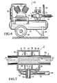
- Vortex tube 6 Details of the vortex tube 6 are shown in Figure 4, in which a partial section of the chamber 7 is shown in section and adjacent to the pipe 8.
- a vortex chamber 18 In the vortex tube 6 there is a vortex chamber 18, to which compressed air is supplied via an inlet channel 19.
- the inlet channel 19 opens into an annular channel 20, from which in turn numerous niche openings, not specified, lead into the swirl chamber 18 in the tangential direction.
- the swirl chamber 18 is delimited at one end by an aperture 23, which widens toward the cold air outlet 24 in the shape of a nozzle.
- the cold air outlet 24 is located at the end of a pipe socket 25 which is inserted into the connecting piece 12 of the chamber 7.
- the warm air outlet 26 is designed as an adjustable annular gap and represents a throttle point, the so-called "warm air throttle".
- the warm air outlet 26 is provided with an actuator 27, which is screwed into a bore 28 at the end 29 of the swirl tube 6 on the hot air side in its housing 30. According to the pitch of the thread, the outlet cross section of the hot air throttle can be adjusted by turning the actuator 27.
- the effect of the vortex tube is based on the formation of a strong vortex, the axis of which coincides with the axis of the vortex chamber 18. From the pressure and speed field of the vortex it follows that the temperature increases strongly towards the outside.
- the inner parts of the vertebra work by braking on the outer parts.
- the outlet temperatures of the air result from the distribution of the temperatures.
- the heat supplied to the warm part of the air is equal to the heat extracted from the cold part. Since the air flows into the pipe at supersonic speed, the air cools down from room temperature to -50 ° C, whereby temperatures up to 200 ° C can occur at the warm end.
- a connection piece 32 is provided in the area of the gas outlet opening 15 of the chamber 7, to which a hose 33 is attached.
- the hose 33 is connected to a pre-cooler 34, through the air suction opening 35 of which the air to be compressed by the compressor 3 is sucked in, pre-cooled and then introduced into the compressor 3. This makes it possible to allow the vortex tubes 6 to flow with pre-cooled compressed air, so that the freezing effect is increased.
- FIG. 6 shows a portable (mobile) compressor 3 with a cooling device 36 for the compressed air and a compressed air tank 37.
- This compressed air tank is provided with wheels 38, a support 39 and a handle bracket 40.
- a vortex tube 6 is structurally combined with the pressure vessel 37, the inlet channel 19 of which is directly connected to the compressed air vessel 37.
- the actuator 27, not shown here, is provided with an adjusting knob 41 protruding from the housing 30 of the swirl tube 6.
- the cold air outlet 24 located at the opposite end of the vortex tube is connected via a thermally insulated hose line 42 to at least one chamber 7, not shown in FIG. In the present case, only one vortex tube is required, and the cold air is distributed to the individual chambers 7 by a distributor, not shown here.
- the tube freezer 43 of Figure 6 also has two pressure gauges 44 and 45 for the detection of the characteristic pressures P1 and P2 here.
- Figure 7 shows a chamber 7 with a particularly strong cooling effect.
- the chamber 7 is divided in the direction of the axis A-A of the pipeline 8 to be frozen by baffles 7a and 7b into three sub-chambers 46, 47 and 48 which are connected to one another by openings 7c and 7b.
- the gas inlet opening 12a is assigned to the middle subchamber 47, and the gas outlet openings 15 are arranged in the subchambers 46 and 48 located at the ends. This ensures that the relaxed cold air is led around the pipeline several times. It is expedient to direct the cold air as directly as possible onto the surface 8a of the pipeline 8. Due to the cooling effect, a so-called ice plug 49 forms inside the pipeline 8, which reliably closes the pipeline 8.
- the chamber 7 In order to mount the chamber 7 on the pipeline 8, it is designed to be divided in an axial plane and provided with a hinge, which is indicated here by the dashed line 50.
- the chamber 7 consists of two half-shells.
- the gas outlet openings 15 are combined in a common manifold 51.
Landscapes
- Engineering & Computer Science (AREA)
- General Engineering & Computer Science (AREA)
- Mechanical Engineering (AREA)
- Physics & Mathematics (AREA)
- Thermal Sciences (AREA)
- Pipe Accessories (AREA)
- Devices That Are Associated With Refrigeration Equipment (AREA)
Abstract
Verfahren und Vorrichtung zum Verschließen von Rohrleitungen (8) durch örtlich begrenztes Einfrieren ihres Inhalts mittels eines auf die Außenwand der Rohrleitung einwirkenden Kühlmediums. Zum Zwecke einer Vermeidung giftiger und/oder anderweitig gefährlicher Gase und zur unmittelbaren Kühlung der Rohrleitung (8) entspannt man unter Druck stehende Luft auf eine Temperatur unterhalb des Gefrierpunktes des Inhaltes der Rohrleitung und richtet die entspannte Luft auf die Außenwand der Rohrleitung. Die Vorrichtung besitzt eine an der Rohrleitung anbringbare Kammer (7), die über eine Gaseintrittsöffnung (12a) mit einer Druckluftquelle verbunden ist und einen Kanal (14) aufweist, der zur Rohrleitung (8) hin offen, zur Atmosphäre hin aber bis auf eine Gasaustrittsöffnung geschlossen ist. Zwischen der Druckluftquelle und der Eintrittsöffnung (12a) der Kammer (7) ist eine Entspannungseinrichtung (5) für die Druckluft angeordnet, die vorzugsweise als Wirbelrohr (6) ausgebildet ist. 
Description
Die Erfindung betrifft ein Verfahren zum Verschließen von Rohrleitungen durch örtlich begrenztes Einfrieren ihres Inhalts mittels eines auf die Außenwand der Rohrleitung einwirkenden Kühlmediums.The invention relates to a method for closing pipelines by locally freezing their contents by means of a cooling medium acting on the outer wall of the pipeline.
Derartige Verfahren sind in größerer Zahl und teilweise seit langer Zeit bekannt:Such methods have been known in large numbers and in some cases for a long time:
Bei einer ersten Gruppe von Verfahren kommen Vorrichtungen zum Einsatz, die aus zwei allseitig geschlossenen Halbzylinder-Schalen bestehen, durch die flüssige Kältemittel im Kreislauf umgewälzt werden oder in die ein festes Kältemittel wie Kohlensäure-Schnee eingebracht wird (US-PS 2 572 555 und GB-PS 601 278). Durch die zuletzt genannte GB-PS 601 278 ist es auch bekannt, die Wirkung festen Kohlendioxids durch die gleichzeitige Anwesenheit von Flüssigkeiten zu unterstützen, die bei den erforderlichen tiefen Temperaturen nicht selbst einfrieren, wie beispielsweise Methylalkohol. Die Wirkung derartiger Verfahren und Vorrichtungen ist jedoch wegen der zwischen dem Kältemittel und der einzufrierenden Rohrleitung vorhandenen Trennwand begrenzt. Außerdem muß die Bedienungsperson geeignete Kältemittel mit sich führen, bei Verwendung von im Kreislauf umgewälzter Kühlsole auch ein besonderes Kälteaggregat mit einem Wärmetauscher, so daß wegen des zusätzlichen Wärmedurchgangs durch die Wärmetauscherflächen ein zusätzlicher Temperaturgradient entsteht (US-PS 2 572 555).In a first group of methods, devices are used which consist of two half-cylinder shells which are closed on all sides, through which liquid refrigerants are circulated or into which a solid refrigerant such as carbon dioxide snow is introduced (US Pat. Nos. 2,572,555 and GB) -PS 601 278). From the last-mentioned GB-PS 601 278 it is also known to support the effect of solid carbon dioxide by the simultaneous presence of liquids which do not freeze themselves at the required low temperatures, such as methyl alcohol. However, the effectiveness of such methods and devices is limited because of the partition wall present between the refrigerant and the pipeline to be frozen. In addition, the operator must carry suitable refrigerants with him, when using circulating cooling brine also a special refrigeration unit with a heat exchanger, so that an additional temperature gradient arises because of the additional heat transfer through the heat exchanger surfaces (US Pat. No. 2,572,555).
Bei einer zweiten Gruppen von Einfrierverfahren werden Vorrichtungen verwendet, bei denen auf die Trennwand zwischen dem Kältemittel und der Rohroberfläche verzichtet wird, so daß das Kältemittel mit der einzufrierenden Rohrleitung unmittelbar in Berührung gelangt (US-PS 3 559 423 und FR-PS 1 521 628 mit Zusatzpatent 94 489). Sofern hierbei die übliche, ätzende Kühlsole verwendet wird, muß auf absolute Dichtigkeit des Kältemittelkreislaufes geachtet werden, und außerdem ist auch hier ein Kälteaggregat mit einem Wärmetauscher erforderlich (US-PS 3 559 423).In a second group of freezing processes, devices are used in which the partition wall between the refrigerant and the pipe surface is dispensed with, so that the refrigerant comes into direct contact with the pipeline to be frozen (US Pat. No. 3,559,423 and FR Pat. No. 1,521,628 with additional patent 94 489). Provided that the usual, caustic cooling brine is used, attention must be paid to absolute tightness of the refrigerant circuit, and also a refrigeration unit with a heat exchanger is also required here (US Pat. No. 3,559,423).
Bei einer dritten Gruppe derartiger Verfahren wird eine Vorrichtung mit einer Kammer verwendet, die gleichfalls zur Rohrleitung hin keine Trennwand aufweist, die aber gegenüber der Rohrleitung auch nur bedingt abgedichtet werden muß, weil das in seinem Endzustand gasförmige Kältemittel ohnehin in mehr oder weniger große Entfernung von der Kammer, die als sogenannte "Manschette" ausgebildet ist, in die Umgebung abgeleitet wird (GB-PS 1 209 144 und DE-PS 23 30 807. Als Kältemittel wird hierbei ein Flüssiggas verwendet, das in einem dünnwandigen Behälter unter geringem Druck in diesem Zustand gehalten werden kann. Nach der Druckentlastung tritt das Flüssiggas in noch flüssigem Zustand mit der Rohrleitung in Wechselwirkung und entzieht dieser die sogenannte Verdampfungswärme. Obwohl dieser Vorgang ein außerordentlich wirkungsvolles Einfrieren der Rohrleitung ermöglicht, ist er im Hinblick auf die zum Einsatz kommenden Flüssiggase bedenklich. Wird hierbei eine bestimmte Art von Fluor-Kohlenwasserstoffen verwendet, so sind die Abgase spätestens nach ihrem Eintreten in eine offene Flamme giftig, werden hierbei reine Kohlenwasserstoffe verwendet, so sind diese im Gemisch mit der Umgebungsluft bei bestimmten Konzentrationen explosiv, so daß die Anwendung nur im Freien oder in gut durchlüfteten Räumen empfohlen werden kann.In a third group of such methods, a device with a chamber is used, which likewise does not have a partition wall towards the pipeline, but which only has to be sealed against the pipeline to a limited extent because the gaseous refrigerant in its final state is at a greater or lesser distance anyway the chamber, which is designed as a so-called "cuff", is derived into the environment (GB-
Für Montage- oder Reparaturarbeiten an Rohrleitungssystemen wie z.B. an wasserführenden Warmwasserheizungsanlagen wurden auch bereits die vorstehend beschriebenen Verfahren und Vorrichtungen angewandt, um bestimmte Rohrleitungsabschnitte abzusperren, ohne die übrigen Rohrleitungsabschnitte oder gar das gesamte Rohrleitungsnetz entleeren und hinterher wieder entlüften zu müssen. Dabei wird das in der Leitung befindliche Wasser unmittelbar vor und hinter der zu reparierenden Stelle zu einem Eispfropfen gefroren, der die Reparaturstelle gegen den Rest des Rohrleitungssystems dicht verschließt. Die betreffenden Arbeiten finden also in der Regel in mehr oder weniger geschlossenen Räumen statt.For assembly or repair work on piping systems such as The methods and devices described above have also already been applied to water-bearing hot water heating systems in order to shut off certain pipe sections without having to empty the other pipe sections or even the entire pipe network and then to vent them again afterwards. The water in the pipe is frozen immediately in front of and behind the point to be repaired to an ice plug, which seals the repair point tightly against the rest of the piping system. The work in question usually takes place in more or less closed rooms.
Um hierbei während der Dauer der Arbeiten ein Auftauen des Eispfropfens zu verhindern, muß der Kühlvorgang weiter fortgesetzt werden. Hierbei werden je nach dem Rohrdurchmesser und Rohrwerkstoff sowie nach der Wassertemperatur unterschiedliche Mengen von verdampften Flüssiggasen an die Raumluft abgegeben. Neben dem relativ hohen Preis der bekannten Kältemittel besteht nicht nur der bereits beschriebene Nachteil einer Personengefährdung, sondern auch in erheblichem Umfange eine Umweltbeeinträchtigung, insbesondere durch die bereits genannten Fluor-Chlor-Kohlenwasserstoffe. Die bekannten "Ozonlöcher" im Bereich der Polkappen sind nur ein Teil der äußerst negativen Folgen.In order to prevent the ice plug from thawing during the work, the cooling process must be continued. Depending on the pipe diameter and pipe material as well as the water temperature, different amounts of vaporized liquid gases are released into the room air. In addition to the relatively high price of the known refrigerants, there is not only the disadvantage of endangering people, as described above, but also considerable environmental damage, in particular due to the fluorine-chlorohydrocarbons mentioned above. The well-known "ozone holes" in the area of the polar caps are only part of the extremely negative consequences.
Der Erfindung liegt daher die Aufgabe zugrunde, ein Verfahren der eingangs beschriebenen Gattung anzugeben, mit dem eine unmittelbare Kühlung der einzufrierenden Rohrleitung möglich ist, ohne daß hierbei giftige und/oder anderweitig gefährliche Gase (Explosionsgefahr) an die Umgebung abgegeben werden.The invention is therefore based on the object of specifying a method of the type described at the outset with which direct cooling of the freeze-up is possible Pipeline is possible without toxic and / or otherwise hazardous gases (risk of explosion) being released into the environment.
Die Lösung der gestellten Aufgabe erfolgt bei dem eingangs beschriebenen Verfahren erfindungsgemäß dadurch, daß man unter Druck stehende Luft auf eine Temperatur unterhalb des Gefrierpunktes des Inhalts der Rohrleitung entspannt und die entspannte Luft auf die Außenwand der Rohrleitung richtet.The object is achieved in the method described above according to the invention in that pressurized air is released to a temperature below the freezing point of the contents of the pipeline and the relaxed air is directed towards the outer wall of the pipeline.
Es ist natürlich bereits bekannt, daß die Temperatur komprimierter Luft bei einer adiabatischen Entspannung nach Maßgabe der Druckdifferenz absinkt. Es wurde aber überraschend festgestellt, daß man diesen an sich bekannten thermodynamischen Effekt mit ganz besonderem Vorteil beim lokalen Einfrieren von Rohrleitungen anwenden kann, so daß keine Veränderung der Umgebungsluft durch die Freisetzung von giftigen und/oder ätzenden Flüssigkeiten bzw. von giftigen und/oder brennbaren (explosiven) Gasen erfolgt.It is of course already known that the temperature of compressed air decreases with an adiabatic relaxation in accordance with the pressure difference. However, it was surprisingly found that this thermodynamic effect, which is known per se, can be used with very particular advantage when freezing pipelines locally, so that there is no change in the ambient air due to the release of toxic and / or caustic liquids or of toxic and / or combustible (explosive) gases occur.
Es ist dabei besonders vorteilhaft, wenn man der Umgebung der Rohrleitung die benötigte Luft entnimmt, diese auf einen Druck P₁ verdichtet, der ausreicht, um bei der Entspannung der abgekühlten Luft auf einen darunterliegenden Druck P₂ den Gefrierpunkt des Inhalts der Rohrleitung zu unterschreiten, der verdichteten Luft Wärme entzieht und sie nachfolgend auf den Druck P₂ entspannt und auf die Außenwand der Rohrleitung richtet.It is particularly advantageous if one removes the required air from the vicinity of the pipeline, compresses it to a
Für die Durchführung eines solchen Verfahrens wird im einfachsten Fall ein Kompressor mit einem Luftkühler und einem Druckbehälter benötigt. Derartige Aggregate, die leicht zu transportieren sind, befinden sich als Druckluftquellen für Spritzpistolen oder dergleichen im Handel.In the simplest case, a compressor with an air cooler and a pressure vessel is required to carry out such a method. Such units, which are easy to transport, are commercially available as compressed air sources for spray guns or the like.
Es bedarf dann nur noch einer entsprechend konstruierten "manschette" um die entspannte und abgekühlte Luft in einen möglichst innigen Wärmeaustausch mit der einzufrierenden Rohrleitung zu bringen.All that is then required is an appropriately designed "sleeve" to bring the relaxed and cooled air into the most intimate possible heat exchange with the pipeline to be frozen.
Ein besonders wirksames Verfahren zum örtlichen Einfrieren von Rohrleitungen unter Verwendung von Umgebungsluft ist gemäß einer weiteren Ausgestaltung der Erfindung dadurch gekennzeichnet, daß man die verdichtete und abgekühlte Luft zunächst im wesentlichen tangential in ein Wirbelrohr mit einem Kaltluftausgang in Form einer Blende und einem Warmluftausgang leitet und in diesem Wirbelrohr zumindest überwiegend entspannt, wobei ein Teil der entspannten Luft durch Wärmeabgabe an den übrigen Teil der entspannten Luft weiter abgekühlt und durch den Kaltluftausgang mit der Blende der einzufrierenden Rohrleitung zugeführt wird, und wobei der übrige, durch eine entsprechende Wärmeaufnahme aufgeheizte Teil der Luft durch den besagten Warmluftausgang abgeführt wird.A particularly effective method for the local freezing of pipes using ambient air is characterized in accordance with a further embodiment of the invention in that the compressed and cooled air is first passed substantially tangentially into a vortex tube with a cold air outlet in the form of an orifice and a warm air outlet and in this vortex tube is at least predominantly relaxed, with part of the relaxed air being cooled further by giving off heat to the remaining part of the relaxed air and being fed through the cold air outlet with the orifice to the pipeline to be frozen, and the remaining part of the air being heated by a corresponding heat absorption by the said warm air outlet is discharged.
Auch ein solches "Wirbelrohr" ist - für sich genommen - Stand der Technik; es wird in der Literatur auch als "Ranquesches Wirbelrohr" bezeichnet (siehe Brockhaus "abc Physik", VEB F.A. Brockhaus Verlag, Leipzig, 1973, Seite 1738, Stichwort: "Wirbelrohr"). Dieses Wirbelrohr wird auch als Kältemaschine ohne bewegliche Teile bezeichnet. Es heißt jedoch, daß das Wirbelrohr einen schlechten Wirkungsgrad hat und für die Kälteerzeugung heute noch keine technische Bedeutung besitzt.Such a "vortex tube" is - in itself - state of the art; it is also referred to in the literature as "Ranquesches vortex tube" (see Brockhaus "abc physics", VEB FA Brockhaus Verlag, Leipzig, 1973, page 1738, keyword: "vortex tube"). This swirl tube will also called a chiller with no moving parts. However, it is said that the vortex tube has a poor efficiency and is still of no technical importance for refrigeration today.
Die Erfindung bezieht sich auch auf eine Vorrichtung zum Verschließen von Rohrleitungen durch örtlich begrenztes Einfrieren ihres Inhalts mittels einer an der Rohrleitung anbringbaren Kammer, die über eine Gaseintrittsöffnung mit einer Quelle eines Kühlmediums verbindbar ist und einen Innenraum aufweist, der zur Rohrleitung hin offen, zur Atmosphäre hin aber bis auf einen Gasauslaß geschlossen ist.The invention also relates to a device for closing pipelines by locally freezing their contents by means of a chamber which can be attached to the pipeline and which can be connected to a source of a cooling medium via a gas inlet opening and has an interior space which is open to the pipeline and to the atmosphere but is closed except for a gas outlet.
Zur Lösung der gleichen Aufgabe ist eine solche Vorrichtung erfindungsgemäß dadurch gekennzeichnet, daß die Quelle für das Kühlmedium eine Druckluftquelle und eine zwischen dieser und der Eintrittsöffnung der Kammer angeordnete Entspannungseinrichtung für die Druckluft ist.To achieve the same object, such a device is characterized according to the invention in that the source for the cooling medium is a compressed air source and a relaxation device for the compressed air arranged between the latter and the inlet opening of the chamber.
In ganz besonders vorteilhafter Weise ist
- a) die Entspannungseinrichtung ein Wirbelrohr mit einem an seinem einen Ende liegenden Kaltluftausgang, einem am entgegengesetzten Ende liegenden Warmluftausgang, einer zwischen den Enden liegenden Blende mit mindestens einem zwischen der Blende und dem Warmluftausgang tangential in das Rohr einmündenden Lufteintrittskanal, wobei der Kaltluftausgang auf der gegenüberliegenden Seite der Blende liegt, und weiterhin ist
- b) der Kaltluftausgang des Wirbelrohres mit der Eintrittsöffnung der Kammer verbunden.
- a) the expansion device has a swirl tube with a cold air outlet at one end, a warm air outlet at the opposite end, an orifice located between the ends with at least one air inlet duct opening tangentially into the tube between the orifice and the warm air outlet, the cold air outlet being on the opposite end Side of the aperture lies, and is still
- b) the cold air outlet of the vortex tube is connected to the inlet opening of the chamber.
Die Erfindung besteht also in einer besonders vorteilhaften Form in der Verwendung eines an sich bekannten Wirbelrohres für einen neuen Zweck, nämlich für das Einfrieren von mediendurchströmten Rohrleitungen.The invention therefore consists in a particularly advantageous form in the use of a vortex tube known per se for a new purpose, namely for freezing pipelines through which media flows.
Es ist dabei weiterhin von Vorteil, wenn die Kammer auf ihrer Innenseite Leiteinrichtungen aufweist, durch die im Zusammenwirken mit der Rohr-Außenfläche die Kaltluft auf verlängerten Strömungswegen über die Rohr-Außenfläche geführt werden kann.It is also advantageous if the inside of the chamber has guide devices through which, in cooperation with the outer surface of the pipe, the cold air can be guided over the outer surface of the pipe along extended flow paths.
Durch die Verwendung eines Wirbelrohres, das mit der besagten Kammer verbunden wird, kann die Druckluft, die z.B. ein tragbarer Kleinkompressor liefert, vor dem Einströmen in die Gefriermanschette auf Temperaturen zwischen etwa -30 °C und -50 °C abgekühlt werden. Diese Abkühlung der Luft erfolgt ohne mechanische bewegte Teile und ohne Zuführen anderer Energien im Bereich des Wirbelrohres. Die abgekühlte Druckluft kühlt in der besagten Kammer das umschlossene Rohr und das darin enthaltene Wasser weit unter den Gefrierpunkt des Wassers ab, was zur Bildung des erforderlichen Eispfropfens und zum Verschluß des Rohres führt. Eine Belastung der Raumluft entfällt damit völlig. Für den Vorgang des Einfrierens von Rohren ist eine zusätzliche Raumlüftung nicht erforderlich, und die für den Kompressor benötigte elektrische Energie kann dem in Gebäuden regelmäßig vorhandenen Leitungsnetz entnommen werden.By using a vortex tube, which is connected to said chamber, the compressed air, which is supplied, for example, by a portable small compressor, can be cooled to temperatures between approximately -30 ° C. and -50 ° C. before it flows into the freezer sleeve. This cooling of the air takes place without mechanical moving parts and without supplying other energies in the area of the vortex tube. The cooled compressed air in the said chamber cools the enclosed tube and the water contained therein far below the freezing point of the water, which leads to the formation of the required ice plug and the closure of the tube. There is no pollution of the room air. Additional room ventilation is not required for the process of freezing pipes, and the electrical energy required for the compressor can be taken from the pipe network that is regularly available in buildings.
Im Rahmen einer weiteren Fortbildung der Erfindung ist es ganz besonders zweckmäßig, im Warmluftausgang des Wirbelrohres eine einstellbare Strömungsdrossel für die Warmluftströmung anzuordnen.As part of a further development of the invention, it is particularly expedient to arrange an adjustable flow restrictor for the warm air flow in the warm air outlet of the vortex tube.
Hierdurch ist es möglich, das Wirbelrohr hinsichtlich der Kälteleistung jeweils optimal einzustellen. Die Betriebspunkte eines solchen Wirbelrohres hinsichtlich minimaler Temperatur einerseits und maximaler Kälteleistung andererseits fallen nämlich nicht zusammen, so daß das Wirbelrohr wahlweise entweder auf eine minimale Lufttemperatur oder eine maximale Kälteleistung oder auf Zwischenwerte eingestellt werden kann.This makes it possible to optimally adjust the vortex tube with regard to the cooling capacity. The operating points of such a vortex tube with regard to minimum temperature on the one hand and maximum cooling capacity on the other hand do not coincide, so that the vortex tube can either be set to a minimum air temperature or a maximum cooling capacity or to intermediate values.
Weiterhin ist es mit besonderem Vorteil möglich, die aus der Kammer bzw. Manschette austretende Kühlluft, die naturgemäß noch nicht die Temperatur der Umgebungsluft erreicht hat, wieder in den Kühlkreislauf, d.h. zum Kompressor zurückzuführen, oder sie einem Wärmetauscher zuzuleiten, durch den die dem Wirbelrohr zugeführte Kompressor-Luft bereits entsprechend vorgekühlt wird.Furthermore, it is particularly advantageously possible for the cooling air emerging from the chamber or sleeve, which of course has not yet reached the temperature of the ambient air, back into the cooling circuit, i.e. to the compressor, or to feed them to a heat exchanger, through which the compressor air supplied to the vortex tube is already pre-cooled accordingly.
Weitere vorteilhafte Ausgestaltungen des Erfindungsgegenstandes ergeben sich aus den übrigen Unteransprüchen.Further advantageous embodiments of the subject matter of the invention emerge from the remaining subclaims.
Ausführungsbeispiele des Erfindungsgegenstandes werden nachstehend anhand der Figuren 1 bis 7 näher erläutert.Exemplary embodiments of the subject matter of the invention are explained in more detail below with reference to FIGS. 1 to 7.
Es zeigen:
Figur 1 die Verwendung einer Vorrichtung mit zwei Wirbelrohren und zwei Kammern an einem Heizungssystem,Figur 2 eine Kammer in Form einer Manschette in einer perspektivischen Ansicht,Figur 3 eine Kammer nachFigur 2 an einer Rohrleitung in baulicher Vereinigung mit einem Wirbelrohr,Figur 4 die Anordnung nachFigur 3 im Schnitt und in vergrößertem Maßstab,Figur 5 eine weitere Ausgestaltung des Gegenstandes nach denFiguren 3 und 4 mit einer Rückführung der Kaltluft zum Kompressor,Figur 6 eine Seitenansicht eines Kompressors mit Druckbehälter sowie in baulicher Vereinigung mit einem Wirbelrohr undFigur 7 einen Axialschnitt durch eine Rohrleitung mit aufgesetzter Kammer während des Betriebes.
- 1 shows the use of a device with two vortex tubes and two chambers on a heating system,
- FIG. 2 shows a chamber in the form of a sleeve in a perspective view,
- 3 shows a chamber according to FIG. 2 on a pipeline in structural union with a swirl tube,
- FIG. 4 shows the arrangement according to FIG. 3 in section and on an enlarged scale,
- 5 shows a further embodiment of the object according to FIGS. 3 and 4 with a return of the cold air to the compressor,
- Figure 6 is a side view of a compressor with pressure vessel and in structural association with a vortex tube and
- 7 shows an axial section through a pipeline with an attached chamber during operation.
Das in Figur 1 dargestellte Rohr-Einfriergerät 1 besitzt eine Druckluftquelle 2 mit einem Kompressor 3. Die Druckluftquelle 2 ist mittels zweier Schläuche 4 mit zwei Entspannungseinrichtungen 5 verbunden, die als Wirbelrohre 6 ausgeführt sind. Die Wirbelrohre 6 sind wiederum an manschettenförmige Kammern 7 angeschlossen, die um Rohrleitungen 8 herumgelegt sind. Durch die Einfrierwirkung mittels der Kammern 7 kann ein Heizkörper 9 von einem Rohrnetz gelöst werden, das hier durch ein Steigrohr 10 und ein Fallrohr 11 angedeutet ist. Durch die Einfrierstellen im Bereich der Kammern 7 entfällt eine Entleerung des gesamten Systems.The
Die Kammern 7 besitzen einen Anschlußstutzen 12 mit einer Gaseintrittsöffnung 12a, an die mittels formschlüssiger Verbindungselemente 13 der Kaltluftausgang des Wirbelrohrs 6 angeschlossen werden kann. In der Kammer 7 ist innenseitig ein umlaufender Kanal 14 ausgebildet, und im Bereich der Gasaustrittsöffnung 15 ist eine Spannschraube 16 vorgesehen, mittels der die Kammer 7 fest an der jeweiligen Rohrleitung 8 zur Anlage gebracht werden kann (Figuren 2 und 3).The
In Figur 3 ist schematisch dargestellt, in welcher Weise eine Kammer 7 mit einem Wirbelrohr 6 an einer Rohrleitung 8 befestigt ist. Das Wirbelrohr 6 ist über einen Rohrstutzen 17 mit dem Schlauch 4 verbunden.FIG. 3 shows schematically the manner in which a
Einzelheiten des Wirbelrohres 6 gehen aus Figur 4 hervor, in der ein Teilausschnitt aus der Kammer 7 im Schnitt und an der Rohrleitung 8 anliegend dargestellt ist. Im Wirbelrohr 6 befindet sich eine Wirbelkammer 18, der über einen Einlaßkanal 19 Druckluft zugeführt wird. Der Einlaßkanal 19 mündet in einen Ringkanal 20, von dem aus wiederum zahlreiche nicht näher bezeichnete Spaltöffnungen in tangentialer Richtung in die Wirbelkammer 18 führen. Zum Einlaßkanal 19 gehört eingangsseitig der Rohrstutzen 17, auf dem der Schlauch 4 aufgeschoben und mittels einer Schlauchschelle 22 befestigt ist.Details of the
Die Wirbelkammer 18 ist an ihrem einen Ende von einer Blende 23 begrenzt, die sich zum Kaltluftaustritt 24 hin düsenförmig erweitert. Der Kaltluftaustritt 24 befindet sich am Ende eines Rohrstutzens 25, der in den Anschlußstutzen 12 der Kammer 7 eingesetzt ist.The
Am entgegengesetzten Ende der Wirbelkammer 18 befindet sich ein Warmluftaustritt 26, der als einstellbarer Ringspalt ausgebildet ist und eine Drosselstelle darstellt, die sogenannte "Warmluftdrossel". Hierzu ist der Warmluftaustritt 26 mit einem Stellglied 27 versehen, das in eine Bohrung 28 am warmluftseitigen Ende 29 des Wirbelrohres 6 in dessen Gehäuse 30 eingeschraubt ist. Entsprechend der Steigung des Gewindes kann durch Drehen des Stellgliedes 27 der Austrittsquerschnitt der Warmluftdrossel verstellt werden.At the opposite end of the
Die Wirkung des Wirbelrohres beruht auf der Bildung eines starken Wirbels, dessen Achse mit der Achse der Wirbelkammer 18 zusammenfällt. Aus dem Druck- und Geschwindigkeitsfeld des Wirbels folgt, daß die Temperatur nach außen stark zunimmt. Die inneren Teile des Wirbels leisten durch ihre Abbremsung an den äußeren Teilen Arbeit. Die Austrittstemperaturen der Luft resultieren aus der Verteilung der Temperaturen. Die dem warmen Teil der Luft zugeführte Wärme ist gleich der dem kalten Teil entzogenen Wärme. Da die Luft mit Überschallgeschwindigkeit in das Rohr einströmt, erfolgt eine Abkühlung der Luft von Zimmertemperatur bis auf -50 °C, wobei am warmen Ende Temperaturen bis 200 °C auftreten können.The effect of the vortex tube is based on the formation of a strong vortex, the axis of which coincides with the axis of the
Bei dem Rohr-Einfriergerät 31 nach Figur 5 ist im Bereich der Gasaustrittsöffnung 15 der Kammer 7 ein Anschlußstutzen 32 vorgesehen, an dem ein Schlauch 33 befestigt ist. Der Schlauch 33 ist mit einem Vorkühler 34 verbunden, durch dessen Luftansaugöffnung 35 die vom Kompressor 3 zu verdichtende Luft angesaugt, vorgekühlt und dann in den Kompressor 3 eingeleitet wird. Hierdurch ist es möglich, den Wirbelrohren 6 bereits vorgekühlte Druckluft zuströmen zu lassen, so daß die Gefrierwirkung erhöht wird.In the
Figur 6 zeigt einen transportablen (fahrbaren) Kompressor 3 mit einer Kühleinrichtung 36 für die komprimierte Luft und einem Druckluftbehälter 37. Dieser Druckluftbehälter ist mit Rädern 38, einer Stütze 39 und einem Griffbügel 40 versehen. Mit dem Druckbehälter 37 ist ein Wirbelrohr 6 baulich vereinigt, dessen Einlaßkanal 19 unmittelbar mit dem Druckluftbehälter 37 verbunden ist. Das hier nicht gezeigte Stellglied 27 ist mit einem aus dem Gehäuse 30 des Wirbelrohres 6 herausragenden Einstellknopf 41 versehen. Der am entgegengesetzten Ende des Wirbelrohres befindliche Kaltluftausgang 24 ist über eine thermisch isolierte Schlauchleitung 42 mit mindestens einer in Figur 6 nicht dargestellten Kammer 7 verbunden. Im vorliegenden Fall wird nur ein Wirbelrohr benötigt, und die Kaltluftverteilung zu den einzelnen Kammern 7 erfolgt durch einen hier nicht gezeigten Verteiler.FIG. 6 shows a portable (mobile)
Das Rohr-Einfriergerät 43 nach Figur 6 besitzt zusätzlich zwei Manometer 44 und 45 für die Erfassung der hier charakteristischen Drücke P₁ und P₂.The
Figur 7 zeigt eine Kammer 7 mit einem besonders starken Kühleffekt. Die Kammer 7 ist in Richtung der Achse A-A der einzufrierenden Rohrleitung 8 durch Leiteinrichtungen 7a und 7b in drei durch Öffnungen 7c und 7b miteinander in Verbindung stehende Teilkammern 46, 47 und 48 unterteilt. Die Gaseintrittsöffnung 12a ist dabei der mittleren Teilkammer 47 zugeordnet, und die Gasaustrittsöffnungen 15 sind in den an den Enden liegenden Teilkammern 46 und 48 angeordnet. Dadurch wird erreicht, daß die entspannte Kaltluft mehrfach um die Rohrleitung herumgeführt wird. Es ist dabei zweckmäßig, die Kaltluft möglichst unmittelbar auf die Oberfläche 8a der Rohrleitung 8 zu richten. Durch den Abkühleffekt bildet sich im Innern der Rohrleitung 8 ein sogenannter Eispfropfen 49 aus, der die Rohrleitung 8 zuverlässig verschließt.Figure 7 shows a
Um die Kammer 7 auf der Rohrleitung 8 anzubringen, ist sie in einer axialen Ebene geteilt ausgebildet und mit einem Scharnier versehen, was hier durch die gestrichelte Linie 50 angedeutet ist. Die Kammer 7 besteht also im Prinzip aus zwei Halbschalen. Die Gasaustrittsöffnungen 15 werden in einer gemeinsamen Sammelleitung 51 vereinigt.In order to mount the
Claims (17)
Applications Claiming Priority (4)
| Application Number | Priority Date | Filing Date | Title |
|---|---|---|---|
| DE8803407U | 1988-03-14 | ||
| DE8803407U DE8803407U1 (en) | 1988-03-14 | 1988-03-14 | Pipe freezing device |
| DE19883815416 DE3815416C1 (en) | 1988-03-14 | 1988-05-06 | |
| DE3815416 | 1988-05-06 |
Publications (2)
| Publication Number | Publication Date |
|---|---|
| EP0332931A2 true EP0332931A2 (en) | 1989-09-20 |
| EP0332931A3 EP0332931A3 (en) | 1991-05-15 |
Family
ID=25867822
Family Applications (1)
| Application Number | Title | Priority Date | Filing Date |
|---|---|---|---|
| EP19890103550 Withdrawn EP0332931A3 (en) | 1988-03-14 | 1989-03-01 | Method for plugging pipelines by freezing and device for carrying out this method |
Country Status (3)
| Country | Link |
|---|---|
| EP (1) | EP0332931A3 (en) |
| JP (1) | JPH0217297A (en) |
| DE (1) | DE3815416C1 (en) |
Cited By (4)
| Publication number | Priority date | Publication date | Assignee | Title |
|---|---|---|---|---|
| US5261619A (en) * | 1992-02-18 | 1993-11-16 | Bobrick Washroom Equipment, Inc. | Toilet tissue dispenser with lock |
| EP1273845A1 (en) * | 2001-05-15 | 2003-01-08 | Rothenberger Werkzeuge Aktiengesellschaft | Apparatus for freezing pipes that are filled with a liquid |
| RU2241170C2 (en) * | 2002-12-17 | 2004-11-27 | Военный инженерно-технический университет | Method of repairing pipelines |
| GB2547709A (en) * | 2016-02-29 | 2017-08-30 | Pttg Ltd | Freezing of pipes |
Families Citing this family (3)
| Publication number | Priority date | Publication date | Assignee | Title |
|---|---|---|---|---|
| SE500121C2 (en) * | 1993-03-18 | 1994-04-18 | Lothar Beise | Method and apparatus for forming plugs in tubes |
| DE19516454A1 (en) * | 1995-05-04 | 1996-11-07 | Alexander Dr Flos | Pipe freezing system for maintenance or repair etc. |
| JP4201311B2 (en) | 2002-03-12 | 2008-12-24 | 株式会社日立メディコ | Ultrasonic diagnostic equipment |
Family Cites Families (9)
| Publication number | Priority date | Publication date | Assignee | Title |
|---|---|---|---|---|
| GB601278A (en) * | 1945-10-12 | 1948-05-03 | Thomas Nicholas Young | Improvements relating to apparatus for use in freezing liquid-containing pipes |
| US2572555A (en) * | 1944-11-03 | 1951-10-23 | Freez Seal Equipment Company L | Water pipe repairing equipment |
| GB1209144A (en) * | 1966-11-25 | 1970-10-21 | Distillers Co Carbon Dioxide | Improvements in or relating to apparatus for freezing liquid in pipes |
| US3559423A (en) * | 1969-08-08 | 1971-02-02 | Werner Scheidler | Equipment for working on liquid-filled conduits |
| GB1425050A (en) * | 1973-05-29 | 1976-02-18 | Flomatic Corp | Pipe freezing device |
| DE2330807C2 (en) * | 1973-06-16 | 1982-03-25 | Flomatic Corp., North Hoosick, N.Y. | Device for freezing a pipeline through which media flows |
| US4339926A (en) * | 1981-08-03 | 1982-07-20 | E. D. Bullard Company | Vortex tube |
| DE8223605U1 (en) * | 1982-08-21 | 1982-12-23 | Sanden, John A. van der, 5601 Eindhoven | DEVICE FOR FORMING A FROZEN PLUG IN A PIPELINE |
| DE3603350A1 (en) * | 1986-02-04 | 1987-08-06 | Walter Prof Dipl Ph Sibbertsen | METHOD FOR COOLING THERMALLY LOADED COMPONENTS OF FLOWING MACHINES, DEVICE FOR CARRYING OUT THE METHOD AND TRAINING THERMALLY LOADED BLADES |
-
1988
- 1988-05-06 DE DE19883815416 patent/DE3815416C1/de not_active Expired
-
1989
- 1989-03-01 EP EP19890103550 patent/EP0332931A3/en not_active Withdrawn
- 1989-03-14 JP JP1059877A patent/JPH0217297A/en active Pending
Cited By (4)
| Publication number | Priority date | Publication date | Assignee | Title |
|---|---|---|---|---|
| US5261619A (en) * | 1992-02-18 | 1993-11-16 | Bobrick Washroom Equipment, Inc. | Toilet tissue dispenser with lock |
| EP1273845A1 (en) * | 2001-05-15 | 2003-01-08 | Rothenberger Werkzeuge Aktiengesellschaft | Apparatus for freezing pipes that are filled with a liquid |
| RU2241170C2 (en) * | 2002-12-17 | 2004-11-27 | Военный инженерно-технический университет | Method of repairing pipelines |
| GB2547709A (en) * | 2016-02-29 | 2017-08-30 | Pttg Ltd | Freezing of pipes |
Also Published As
| Publication number | Publication date |
|---|---|
| EP0332931A3 (en) | 1991-05-15 |
| JPH0217297A (en) | 1990-01-22 |
| DE3815416C1 (en) | 1989-10-12 |
Similar Documents
| Publication | Publication Date | Title |
|---|---|---|
| EP0432583B1 (en) | Cooling device | |
| DE3637071C2 (en) | Method and device for compressing gases | |
| DE1953835A1 (en) | Device for cryosurgery | |
| DE2734358A1 (en) | COLD GENERATION DEVICE | |
| DE2831199B2 (en) | Cryochinirgy device | |
| DE4202802A1 (en) | DEVICE FOR COOLING DRYING GASES | |
| DE19617619A1 (en) | Device or evaporator for freezing a pipe section | |
| DE3815416C1 (en) | ||
| DE2005634A1 (en) | ||
| DE698598C (en) | Device for generating cold | |
| DE3511726C2 (en) | ||
| DE3903009A1 (en) | Device for freezing pipelines through which media flow, in particular water conduits (water piping) | |
| DE3916025C2 (en) | ||
| DE4340689C1 (en) | Method for cooling gases | |
| EP3795885A1 (en) | Gas discharge system with lng generating system | |
| DE2530198C3 (en) | Device for drying gases | |
| DE8803407U1 (en) | Pipe freezing device | |
| DE4034076A1 (en) | DEVICE FOR THE EXPANSION OF LIQUID GASES | |
| EP0316588A1 (en) | Device to expose the outside of a pipe transporting a freezing medium with cooling means | |
| DE102008027182B3 (en) | Device for peripheral freezing of the contents of liquid-carrying pipelines | |
| DE102004058137B3 (en) | Device for locally freezing water-filled pipelines such as heating lines, branched lines and sanitary lines comprises a supporting collar assigned to nozzle openings to be supported on the pipeline on two sites parallel to each other | |
| DE19624462A1 (en) | Freezing appliance for liquid filled pipes, with contact body and expansion chamber for evaporating refrigerant | |
| DE1751714A1 (en) | Method and device for generating cold | |
| DE4436384C2 (en) | Method and device for liquefying gases and gas mixtures | |
| AT405171B (en) | Method for the at least partial evacuation of air from a liquefied gas tank and a compressed-air air pump based on a venturi tube for use in such a method |
Legal Events
| Date | Code | Title | Description |
|---|---|---|---|
| PUAI | Public reference made under article 153(3) epc to a published international application that has entered the european phase |
Free format text: ORIGINAL CODE: 0009012 |
|
| AK | Designated contracting states |
Kind code of ref document: A2 Designated state(s): AT BE CH DE ES FR GB IT LI LU NL SE |
|
| PUAL | Search report despatched |
Free format text: ORIGINAL CODE: 0009013 |
|
| AK | Designated contracting states |
Kind code of ref document: A3 Designated state(s): AT BE CH DE ES FR GB IT LI LU NL SE |
|
| STAA | Information on the status of an ep patent application or granted ep patent |
Free format text: STATUS: THE APPLICATION IS DEEMED TO BE WITHDRAWN |
|
| 18D | Application deemed to be withdrawn |
Effective date: 19911106 |